D2992-01翻译
CT-ERD.22电子定时器说明书
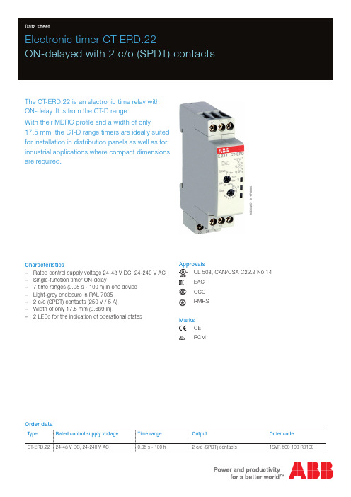
2C D C 251 091 F 0006Electronic timer CT-ERD.22ON-delayed with 2 c/o (SPDT) contactsThe CT-ERD.22 is an electronic time relay with ON-delay. It is from the CT-D range.With their MDRC profile and a width of only17.5 mm, the CT-D range timers are ideally suited for installation in distribution panels as well as for industrial applications where compact dimensions are required.Characteristics–Rated control supply voltage 24-48 V DC, 24-240 V AC –Single-function timer ON-delay–7 time ranges (0.05 s - 100 h) in one device –Light-grey enclosure in RAL 7035 – 2 c/o (SPDT) contacts (250 V / 5 A) –Width of only 17.5 mm (0.689 in)– 2 LEDs for the indication of operational statesApprovalsA UL 508, CAN/CSA C22.2 No.14REAC E CCCLRMRSMarksa CE bRCMOrder dataType Rated control supply voltage Time range OutputOrder codeCT-ERD.2224-48 V DC, 24-240 V AC0.05 s - 100 h2 c/o (SPDT) contacts1SVR 500 100 R01002 - Electronic timer CT-ERD.22 | Data sheetFunctions Operating controls2C D C 251 091 F 00061 Rotary switch for the preselection of the time range2 Potentiometer with direct reading scale for the fine adjustmentof the time delay3 Indication of operational states U: green LEDV control supply voltage applied W timing R: yellow LEDV output relays energized 4 Circuit diagramApplicationWith their structural form and their width of only 17.5 mm, the CT-D range timers are ideally suited for installation indistribution panels.Operating modeThe CT-ERD.22 has 2 c/o (SPDT) contacts and offers 7 time ranges, from 0.05 s to 100 h. The time delay range is rotary switch selectable on the front of the unit. The fine adjustment of the time delay is made via an internal potentiometer, with a direct reading scale, on the front of the unit.Function descriptions / diagramsA ON-delayThis function requires continuous control supply voltage for timing. Timing begins when control supply voltage is applied.The green LED flashes during timing. When the selected time delay is complete, the output relays energize and the flashing green LED turns steady. If control supply voltage is interrupted, the output relays de-energize and the time delay is reset.Electrical connectionData sheet| Electronic timer CT-ERD.22 - 3Data at T a = 25 °C and rated values, unless otherwise indicatedInput circuitsSupply circuit A1-A2Rated control supply voltage U s24-240 V AC, 24-48 V DCRated control supply voltage U s tolerance-15...+10 %Typical current / power consumption24 V DC21 mA / 0.5 W115 V AC20 mA / 1.2 VA230 V AC31mA / 1.9 VARated frequency DC; 50/60 HzFrequency range AC47-63 HzPower failure buffering time min. 20 msRelease voltage> 10 % of the min. rated control supply voltage U sTiming circuitKind of timer Single-function timer ON-delayTime ranges 0.05 s - 100 h0.05-1 s, 0.5-10 s, 5-100 s, 0.5-10 min, 5-100 min, 0.5-10 h, 5-100 h Recovery time< 50 msRepeat accuracy (constant parameters)D t < ± 0.5 %Accuracy within the rated control supply voltage tolerance D t < 0.005 % / VAccuracy within the temperature range D t < 0.06 % / °CSetting accuracy of time delay± 10 % of full-scale valueUser interfaceIndication of operational statesControl supply voltage / timing U: green LED V: control supply voltage appliedW: timingRelay status R: yellow LED V: output relays energizedOutput circuitKind of output15-16/18relay, 1st c/o (SPDT) contact25-26/28relay, 2nd c/o (SPDT) contactContact material Cd-freeRated operational voltage U e250 VMinimum switching voltage / Minimum switching current12 V / 100 mAMaximum switching voltage / Minimum switching current see load limit curve / see load limit curveRated operational current I e AC-12 (resistive) at 230 V 5 AAC-15 (inductive) at 230 V 3 ADC-12 (resistive) at 24 V 5 ADC-13 (inductive) at 24 V 2 AAC rating (UL 508)utilization category(Control Circuit Rating Code)B 300max. rated operational voltage300 V ACmaximum continuous thermal current at B 300 5 Amax. making/breaking apparent power at B 3003600 VA / 360 VAMechanical lifetime30 x 106 switching cyclesElectrical lifetime AC-12, 230 V, 4 A0.1 x 106 switching cyclesMaximum fuse rating to achieve short-circuit protection n/c contact 6 A fast-acting n/o contact10 A fast-acting4 - Electronic timer CT-ERD.22 | Data sheetMTBF on requestDuty time100 %Dimensions (W x H x D)product dimensions17.5 x 80 x 58 mm (0.69 x 3.15 x 2.28 in)packaging dimensions89 x 65 x 20 mm (3.50 x 2.56 x 0.79 in)Weight Nettogewicht0.068 kg (0.150 lb)Bruttogewicht0.081 kg (0.179 lb)Mounting DIN rail (IEC/EN 60715), snap-on mounting without any tool Mounting position anyMinimum distance to other units, normal operation mode horizontal not necessary vertical not necessaryDegree of protection housing IP50terminals IP20Electrical connectionConnecting capacity fine-strand with wire end ferrule 2 x 0.5-1.5 mm2 / 1 x 0.5-2.5 mm2 (2 x 20-16 AWG / 1 x 20-14 AWG) fine-strand without wire end ferrule 2 x 0.5-1.5 mm2 / 1 x 0.5-2.5 mm2 (2 x 20-16 AWG / 1 x 20-14 AWG)rigid 2 x 0.5-1.5 mm2 / 1 x 0.5-4 mm2 (2 x 20-16 AWG / 1 x 20-12 AWG) Stripping length7 mm (0.28 in)Tightening torque0.5-0.8 Nm (4.43-7.08 lb.in)Environmental dataAmbient temperature ranges operation -20...+60 °C (-4...+140 °F)storage-40...+85 °C (-40...+185 °F)Climatic class (IEC/EN 60068-2-30)3k3Relative humidity range25 % to 85 %Vibration, sinusoidal (IEC/EN 60068-2-6)20 m/s2, 10 cycles, 10...150...10 HzShock, half-sine (IEC/EN 60068-2-27)150 m/s2, 11 msIsolation dataRated insulation voltage U i input circuit / output circuit300 Voutput circuit 1 / output circuit 2300 VRated impulse withstand voltage U imp between all isolated circuits 4 kV; 1.2/50 μsPower-frequency withstand voltage between all isolated circuits(test voltage)2.5 kV, 50 Hz, 60 sBasic insulation (IEC/EN 61140)input circuit / output circuit300 VProtective separation (IEC/EN 61140, EN 50178)input circuit / output circuit250 VPollution degree3Overvoltage category IIIStandards / DirectivesStandards IEC/EN 61812-1Low Voltage Directive2014/35/EUEMC directive2014/30/EURoHS Directive2011/65/ECData sheet| Electronic timer CT-ERD.22 - 56 - Electronic timer CT-ERD.22 | Data sheetElectromagnetic compatibilityInterference immunity toIEC/EN 61000-6-2electrostatic discharge IEC/EN 61000-4-2Level 3 (6 kV / 8 kV)radiated, radio-frequency, electromagnetic fieldIEC/EN 61000-4-3Level 3 (10 V/m)electrical fast transient / burst IEC/EN 61000-4-4Level 3 (2 kV / 5 kHz)surgeIEC/EN 61000-4-5Level 3 (2 kV L-L)conducted disturbances, induced by radio-frequency fields IEC/EN 61000-4-6Level 3 (10 V)Interference emissionIEC/EN 61000-6-3high-frequency radiated IEC/CISPR 22,EN 55022Class Bhigh-frequency conductedIEC/CISPR 22,EN 55022Class BTechnical diagramsLoad limit curvesAC load (resistive) DC load (resistive)Derating factor F for inductive AC loadContact lifetimeDimensionsin mm andinchesFurther documentationDocument title Document type Document numberElectronic products and relays Technical catalogue2CDC 110 004 C02xxCT-D range Instruction manual1SVC 500 010 M1000You can find the documentation on the internet at /lowvoltage-> Automation, control and protection -> Electronic relays and controls -> Electronic timers.CAD system filesYou can find the CAD files for CAD systems at -> Low Voltage Products & Systems -> Control Products -> Electronic Relays and Controls.Data sheet| Electronic timer CT-ERD.22 - 7ABB STOTZ-KONTAKT GmbHP. O. Box 10 16 8069006 Heidelberg, Germany Phone: +49 (0) 6221 7 01-0Fax: +49 (0) 6221 7 01-13 25E-mail:*****************.comYou can find the address of your local sales organisation on theABB home page/contacts-> Low Voltage Products and Systems Contact usNote:We reserve the right to make technical changes or modify the contents of this document without prior notice. With regard to purchase orders, the agreed particulars shall prevail. ABB AG does not accept any responsibility whatsoever for potential errors or possible lack of information in this document.We reserve all rights in this document and in the subject matter and illustrations contained therein. Any reproduction, disclosure to third parties or utilization of its contents – in wholeor in parts – is forbidden without prior written consent of ABB AG.Copyright© 2016 ABBAll rights reserved D o c u m e n t n u m b e r 2 C D C 1 1 1 1 6 0 D 0 2 0 1 ( 0 8 . 2 0 1 6 )。
最新jstd020d(中英文对照版)资料
J-STD-020DMoisture/Reflow Sensitivity Classification for Nonhermetic Solid State Surface Mount Devices非密封固态表面贴装元件湿度/回流焊敏感度分级1 PURPOSE(目的)The purpose of this standard is to identify the classification level of nonhermetic solid state surface mount devices (SMDs) that are sensitive to moisture-induced stress so that they can be properly packaged, stored, and handled to avoid damage during assembly solder reflow attachment and/or repair operations.本标准旨在识别非密封固态表面贴装元件的湿度敏感等级以便其能合适的封装,储存,作业以避免在回流和维修作业中被损伤. This standard may be used to determine what classification/preconditioning level should be used for SMD package qualification. Passing the criteria in this test method is not sufficient by itself to provide assurance of long-term reliability本标准用于判定合格的SMT封装应使用何种等级/预处理水平.依据本测试方法且通过对应判定标准的元件并不能保证其长期可靠性1.1 Scope(范围)This classification procedure applies to all nonhermetic solid state Surface Mount Devices (SMDs) in packages, which, because of absorbed moisture, could be sensitive to damage during solder reflow. The term SMD as used in this document means plastic encapsulated surface mount packages and other packages made with moisture-permeable materials. The categories are intended to be used by SMD producers to inform users (board assembly operations) of the level of moisture sensitivity of their product devices, and by board assembly operations to ensure that proper handling precautions are applied to moisture/reflow sensitive devices. If no major changes have been made to a previously qualified SMD package, this method may be used for reclassification according to 4.2.此分类程序适用于所有非密封固体表面贴装元件,此部分元件由于吸收湿气而在回流焊接中容易损伤. 本文件所提及的术语“SMD”指的是塑封或本体为吸湿材料的元件.分类的目的是为了让元件制造商能告知元件使用者(PCBA组装)其产品的湿敏等级,确保元件使用者能恰当作业,如果对之前认证过的SMD封装没有重大更改,依据4.2此方法亦可用于元件的再次分类.This standard cannot address all of the possible component, board assembly and product design combinations. However, the standard does provide a test method and criteria for commonly used technologies. Where uncommon or specialized components or technologies are necessary, the development should include customer/manufacturer involvement and the criteria should include an agreed definition of product acceptance.此标准不能涵盖所有与设计,组装相关联的元件.但是,此标准为通用技术提供了一个测试方法和标准. 如果使用特殊技术或特殊元件,则需客户以及相关的制造方定义一个双方同意的产品接受标准.SMD packages classified to a given moisture sensitivity level by using Procedures or Criteria defined within any previous version ofJ-STD-020, JESD22-A112 (rescinded), or IPC-SM-786 (rescinded) do not need to be revision unless a change in classification level or a higher peak classification temperature is desired. Annex B provides an overview of major changes from Revision C to Revision D of this document.在使用之前版本J-STD-020,JESD22-A112(已作废),IPC-SM-786(已作废)标准中已分级的湿敏元件除非敏感等级变更或耐温峰值提高,否则无须重新分级.附件B提供了版本C升级到版本D的主要变更.Note: If the procedures in this document are used on packaged devices that are not included in this specification’s scope, the fail ure criteria for such packages must be agreed upon by the device supplier and their end user备注:当封装元件未在本标准规格范围内,如需使用此文件中的流程判定,则不良标准需元件供应商和其客户同意.1.2 Background(背景)The vapor pressure of moisture inside a nonhermetic package increases greatly when the package is exposed to the high temperature of solder reflow. Under certain conditions, this pressure can cause internal delamination of the packaging materials from the die and/or leadframe/substrate, internal cracks that do not extend to the outside of the package, bond damage, wire necking, bond lifting, die lifting, thin film cracking, or cratering beneath the bonds. In the most severe case, the stress can result in external package cracks. This iscommonly referred to as the ‘‘popcorn’’ phenomenon because the internal stress causes the package to bulge and then crack wit h an audible ‘‘pop.’’ SMDs are more susceptible to this problem than through-hole parts because they are exposed to higher temperatures during reflow soldering. The reason for this is that the soldering operation must occur on the same side of the board as the SMD device. For wave-soldered through-hole devices, the soldering operation occurs under the board that shields the devices from the hot solder through-hole devices, the soldering operation occurs under the board that shields the devices from the hot solder Throughhole devices that are soldered using intrusive soldering or ‘‘pin in paste’’ processes may experience the same type of moisture-induced failures as SMT devices.非密封元件封装在回流高温条件下,其内部水蒸气压力猛增.在某一件下,压力将导致封装从内部分层或者内裂,邦定受损。
卡特(Cat)299D2磨合载器的特性说明书

High Flow XPS hydraulic system is available for applications that demand maximum hydraulic work tool performance.
Electronically controlled Cat C3.8 engine provides high horsepower and torque while meeting U.S. EPA Tier 4 Final/EU Stage IV emission standards.
Maximize machine capability and control with the standard Advanced Display providing on-screen adjustments for implement response, hystat response, and creep control, multi-language functionality with customizable layouts, security system, and rearview camera.
Industry leading sealed and pressurized cab option provides a cleaner and quieter operating environment with excellent Work Tool visibility.
诺帝菲尔 302系列 说明书
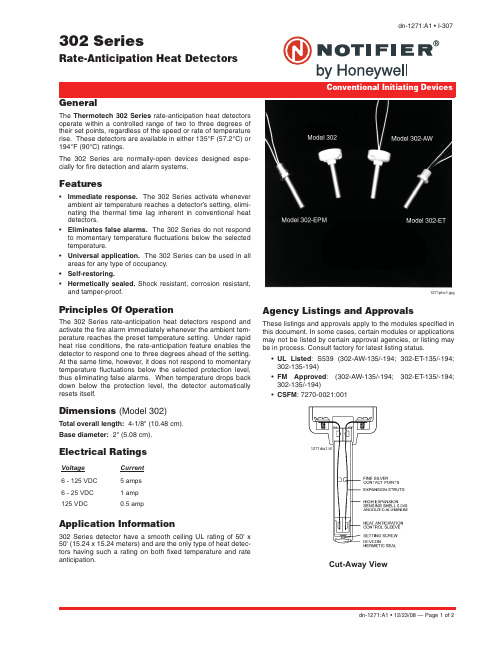
302 SeriesRate-Anticipation Heat Detectorsdn-1271:A1 • I-307GeneralThe Thermotech 302 Series rate-anticipation heat detectorsoperate within a controlled range of two to three degrees oftheir set points, regardless of the speed or rate of temperaturerise. These detectors are available in either 135°F (57.2°C) or194°F (90°C) ratings.The 302 Series are normally-open devices designed espe-cially for fire detection and alarm systems.Features•Immediate response. The 302 Series activate wheneverambient air temperature reaches a detector’s setting, elimi-nating the thermal time lag inherent in conventional heatdetectors.•Eliminates false alarms. The 302 Series do not respondto momentary temperature fluctuations below the selectedtemperature.•Universal application. The 302 Series can be used in allareas for any type of occupancy.•Self-restoring.•Hermetically sealed. Shock resistant, corrosion resistant,and tamper-proof.Principles Of OperationThe 302 Series rate-anticipation heat detectors respond and activate the fire alarm immediately whenever the ambient tem-perature reaches the preset temperature setting. Under rapid heat rise conditions, the rate-anticipation feature enables the detector to respond one to three degrees ahead of the setting. At the same time, however, it does not respond to momentary temperatu re flu ctu ations below the selected protection level, thus eliminating false alarms. When temperature drops back down below the protection level, the detector au tomatically resets itself.Dimensions (Model 302)Total overall length: 4-1/8" (10.48 cm).Base diameter: 2" (5.08 cm).Electrical RatingsApplication Information302 Series detector have a smooth ceiling UL rating of 50' x 50' (15.24 x 15.24 meters) and are the only type of heat detec-tors having such a rating on both fixed temperature and rate anticipation. Agency Listings and ApprovalsThese listings and approvals apply to the modules specified in this document. In some cases, certain modules or applications may not be listed by certain approval agencies, or listing may be in process. Consult factory for latest listing status.•UL Listed: S539 (302-AW-135/-194; 302-ET-135/-194;302-135-194)•FM Approved: (302-AW-135/-194; 302-ET-135/-194;302-135/-194)•CSFM: 7270-0021:001Voltage Current 6 - 125 VDC 5 amps 6 - 25 VDC 1 amp 125 VDC0.5 amp1271pho1.jpgCut-Away View1271dia1.tifdn-1271:A1 • 12/23/08 — Page 1 of 2Page 2 of 2 — dn-1271:A1 • 12/23/08NOTIFIER® is a registered trademark of Honeywell International Inc.©2008 by Honeywell International Inc. All rights reserved. Unauthorized use of this document is strictly prohibited.This document is not intended to be used for installation purposes. We try to keep our product information up-to-date and accurate. We cannot cover all specific applications or anticipate all requirements.All specifications are subject to change without notice.For more information, contact Notifier. Phone: (203) 484-7161, FAX: (203) 484-7118.NOTE 1: For interior mounting in any atmosphere that is compatible with terminal-screw-type connections. UL rating 50' x 50' (15.24 x15.24 meters).NOTE 2: Hermetically sealed for moisture-proof or dust-proof installations. Requires no special backbox when the all-weather leads areproperly spliced to “THW” or equivalent type wire.NOTE 3: Hermetically sealed for moisture-proof or dust-proof installations. Requires no special backbox. Has plastic hexagonal wrenchgrip bushing with 1/2” (1.27 cm) conduit threads for attachment to threaded hub cover, or any outlet box.NOTE 4: Explosion-proof for installation in hazardous locations. Has hexagonal wrench-grip bushing with 1/2” (1.27 cm) conduit threadsfor attachment to threaded hub cover of Series JL fixture fitting as manufactured by Killark Electric Co., or equal.Thermotech Model 302 Series Rate-Anticipation Heat DetectorsModel NumberDescription Refer To302-135135°F Interior Vertical Mounting Note 1 below 302-194194°F Interior Vertical Mounting 302-AW-135135°F All-Weather Vertical Mounting Note 2 below 302-AW-194194°F All-Weather Vertical Mounting 302-ET-135135°F All-Weather Vertical Mounting Note 3 below 302-ET-194194°F All-Weather Vertical Mounting 302-EPM-135135°F Explosion Proof Mounting Note 4 below302-EPM-194194°F Explosion Proof MountingAP-PDecorative white plastic adaptor plate for mounting 302 and 302-AW to 4” outlet box.。
D-27 1

D-271⁄8DIN THERMOCOUPLE METERThe DP24-T is an accurate, reliable, economical digital panel meter for use with thermocouples J, K, T, E, R, S, N, or J DIN. Simple front-panel programming allows selection of max or min (peak or valley) temperatures. The DP24-T has plug-in screw terminalconnections for thermocouple input and power as well as external display hold switches. Its compact depth of only 104 mm (4.10")allows for panel mounting in tight areas. After scaling, the frontkeypad can be locked out to avoidunauthorized changes and anoptional bezel without “buttonholes”can be snapped into place.SPECIFICATIONSAccuracy:±0.5°C (0.9°F) @ 25°C (77°F)Resolution:1.0 or 0.1°(-100 to 1000)Thermocouple Inputs:J, K, T, E, R, S, N, J DIN Operating Temp:0 to 50°C (32 to 122°F)Storage Temp: -40 to 85°C (-40 to 185°F)Display:Red or green LED, 4-digit, 14.2 mm (0.56") highRelative Humidity: 95% @ 40°C (104°F), non-condensingConnections:Plug-in screw terminalsPower RequirementsVoltage: 115 Vac ±15% standard (230 Vac or 10 to 32 Vdc isolated optional)Frequency:50 or 60 HzPower Consumption:2 W maxMechanical SpecificationsDimensions:96 W x 48 H x 104mm D (3.78 x 1.89 x 4.10")Panel Cutout: 92 W x 45 mm H (3.62 x 1.77"), 1⁄8DINDepth Behind Panel:100 mm (3.94")Weight:312 g (11 oz)shown smaller than actual size.power, $225 + 95 = $324.48.00 (1.89)ߜ5-Year Warranty ߜEasy to UseߜSingle-Button °C/°FSelectionߜMin or Max Recall ߜDisplay Hold andBlankingCANADA www.omega.ca Laval(Quebec) 1-800-TC-OMEGA UNITED KINGDOM www. Manchester, England0800-488-488GERMANY www.omega.deDeckenpfronn, Germany************FRANCE www.omega.frGuyancourt, France088-466-342BENELUX www.omega.nl Amstelveen, NL 0800-099-33-44UNITED STATES 1-800-TC-OMEGA Stamford, CT.CZECH REPUBLIC www.omegaeng.cz Karviná, Czech Republic596-311-899TemperatureCalibrators, Connectors, General Test and MeasurementInstruments, Glass Bulb Thermometers, Handheld Instruments for Temperature Measurement, Ice Point References,Indicating Labels, Crayons, Cements and Lacquers, Infrared Temperature Measurement Instruments, Recorders Relative Humidity Measurement Instruments, RTD Probes, Elements and Assemblies, Temperature & Process Meters, Timers and Counters, Temperature and Process Controllers and Power Switching Devices, Thermistor Elements, Probes andAssemblies,Thermocouples Thermowells and Head and Well Assemblies, Transmitters, WirePressure, Strain and ForceDisplacement Transducers, Dynamic Measurement Force Sensors, Instrumentation for Pressure and Strain Measurements, Load Cells, Pressure Gauges, PressureReference Section, Pressure Switches, Pressure Transducers, Proximity Transducers, Regulators,Strain Gages, Torque Transducers, ValvespH and ConductivityConductivity Instrumentation, Dissolved OxygenInstrumentation, Environmental Instrumentation, pH Electrodes and Instruments, Water and Soil Analysis InstrumentationHeatersBand Heaters, Cartridge Heaters, Circulation Heaters, Comfort Heaters, Controllers, Meters and SwitchingDevices, Flexible Heaters, General Test and Measurement Instruments, Heater Hook-up Wire, Heating Cable Systems, Immersion Heaters, Process Air and Duct, Heaters, Radiant Heaters, Strip Heaters, Tubular HeatersFlow and LevelAir Velocity Indicators, Doppler Flowmeters, LevelMeasurement, Magnetic Flowmeters, Mass Flowmeters,Pitot Tubes, Pumps, Rotameters, Turbine and Paddle Wheel Flowmeters, Ultrasonic Flowmeters, Valves, Variable Area Flowmeters, Vortex Shedding FlowmetersData AcquisitionAuto-Dialers and Alarm Monitoring Systems, Communication Products and Converters, Data Acquisition and Analysis Software, Data LoggersPlug-in Cards, Signal Conditioners, USB, RS232, RS485 and Parallel Port Data Acquisition Systems, Wireless Transmitters and Receivers。
NTE2991中文资料

−
− 2.0 44 − − − − − − − − − − − − − − − −
−ห้องสมุดไป่ตู้
8.0 4.0 − 25 250 100 −100 146 35 54 − − − − − − − − −
V/°C
Ω V mhos µA µA nA nA nC nC nC ns ns ns ns nH nH pF pF pF
∆V(BR)DSS/ Reference to +25°C, ID = 1mA ∆TJ RDS(on) VGS(th) gfs IDSS IGSS IGSS Qg Qgs Qgd td(on) tr td(off) tf LD LS Ciss Coss Crss IS ISM VSD trr Qrr ton (Body Diode) (Body Diode) Note 2 TJ = +25°C, IS = 62A, VGS = 0V, Note 5 TJ = +25°C, IF = 62A, di/dt = 100A/µs, Note 5 Between lead, 6mm (0.25”) from package and center of die contact VGS = 0V, VDS = 25V, f = 1MHz VDD = 28V, ID = 62A, RG = 4.5Ω, VGS = 10V, Note 5 VGS = 10V, ID = 62A, Note 5 VDS = VGS, ID = 250µA VDS = 25V, ID = 62A, Note 5 VDS = 55V, VGS = 0 VDS = 44V, VGS = 0V, TC = +150°C VGS = 20V VGS = −20V VGS = 10V, ID = 62A, VDS = 44V
坎诺达尔轮速传感器部件说明书

1 of 4 134946 Rev 1 - Pubblicato il: 05/15/19• Il sensore ruota utilizza un sistema di adattatori di montaggio in due parti per il montaggio su diversi tipi di mozzo/ruota.Vedere pagina 3 Compatibilità dell’adattatore di montaggio. Isegni di identificazione dell’adattatore sono impressi nel supporto dell’adattatore in gomma e nel morsetto dell’adattatore.• Un montaggio diverso del sensore da quello specificato può causare danni al sensore stesso e/o alla ruota o provocare ildistaccamento del sensore ruota.• Il sensore deve essere montato verticalmente rispetto all’interno dei raggi sul lato non di trasmissione della ruota anteriore e deveessere a contatto con due raggi. Tuttavia, quando si pedala alchiuso, il sensore può essere spostato sul lato non di trasmissione della ruota posteriore utilizzando l’adattatore 0A. Ciò può compor-tare una leggera inclinazione del sensore, che non ne pregiudica il funzionamento. Il montaggio del sensore in qualsiasi altro orien-tamento comporta una lettura meno precisa della velocità e della distanza.• Posizionare il sensore ruota e fissarlo il più vicino possibile all’asse del mozzo con la superficie inferiore curva che corrisponda allacurvatura del mozzo.Vedere CORRETTO, INCORRETTO.Strumenti necessari:Occhiali di sicurezza, guanti da lavoro, chiave esagonale: Chiave esa-gonale da 2 mm2431Installazione1. Inserire il supporto dell’adattatore nel corpo del sensore ruota.2. Posizionare il morsetto del raggio sulla ruota come specificato in Compatibilità dell’adattatore di montaggio. Pagina3.3. Posizionare il sensore ruota all’interno dei raggi e allineare il foro del bullone del morsetto di montaggio con il foro del sensore ruota. Premere e tenere insieme le due parti.4.Utilizzando una chiave esagonale da 2 mm, serrare il bullone adattatore a 0,5 Nm, tenendoCompatibilità dell’adattatore di montaggio2ASolo mozzi HollowGram KNØT2BRaggiatura in seconda con il raggio d’uscita sul lato INTERNO della flangia.NOTA: Se il morsetto per raggio non si adatta agli angoli dei raggi, utilizzare l’adattatore dimontaggio 0A.4 of 4Si prega di fare riferimento . alla propria regione per letraduzioni linguistiche disponibili.I termini “componenti” si applicano a questo accessorio. Per ulteriori infor-mazioni, visitare l’area di supporto all’indirizzo .Contattare CannondaleAndare su . per informazioni di contatto perla propria regione.Sostituzione della batteriaVedere anche “Garmin Informazioni importanti sulla sicurezza e sul prodotto”.Per controllare il livello della batteria, far fare due giri alla ruota. Se il LED (a) sul corpo del sensore ruota lampeggia in rosso, il livello della batteria è basso.bcdb“+”ag1. Rimuovere il sensore ruota dalla ruota utilizzando una chiave esagonale da 2 mm.2.Utilizzare una moneta nell’alloggiamento del coperchio (b) e ruotare il coperchio in senso antiorario fino a quando il trattino del coperchio (c) si allinea con il simbolo di sblocco (d) e viene allentato.Se necessario, utilizzare con cautela un piccolo cacciavite piatto sottile posto sotto il lembo del coperchio per sollevarlo. Usare solo una leggera pressione per evitare di danneggiare il coperchio, l’o-ring di guarnizione (e) o il coperchio. Non ruotare il cacciavite.3. Rimuovere la batteria dall’alloggiamento. Attendere 30 secondi.4.Inserire la nuova batteria (g) con il simbolo positivo “+” sulla batteria rivolto verso l’alto. Prendere nota del contrassegno “-” (h) nel coperchio, il contrassegno della batteria deve essere rivolto verso di esso. Individuare delle piccole linguette (f); inclinare leggermente la batteria sotto queste linguette prima di premerla.5.Per reinstallare nell’alloggiamento dell’unità, allineare il trattino del coper-chio (c) con il simbolo di sblocco (d) e inserire il coperchio con la batteria nuova.6.Utilizzare la moneta con una leggera pressione verso il basso e ruotare lo sportello della batteria in senso orario fino a quando il trattino del coperchio è allineato con il simbolo “CHIUSO”. Controllare lo sportello della batteria per assicurarsi che sia a filo con l’alloggiamento e non inclinato, mostrando o stringendo la guarnizione o-ring arancione. Allentare il coperchio e riprovare.NOTA: Il LED (a) lampeggia in rosso e verde per alcuni secondi dopo la sostituzione della batteria. Quando il LED lampeggia in verde e poi smette di lampeggiare, il dispositivo è attivo e pronto per l’invio dei dati.La prima volta che si collega un sensore wireless al dispositivo utilizzando la tecno-logia ANT+® o Bluetooth® , è necessario associare il dispositivo e il sensore. Dopo l’accoppiamento, il dispositivo si collega automaticamente al sensore quando si ini -zia un’attività e il sensore è attivo ed entro il raggio d’azione.NOTA: Le istruzioni di accoppiamento differiscono per ogni dispositivo compatibile con ANT+ o Bluetooth. Vedere il manuale d’uso.• Portare il dispositivo compatibile con ANT+ o Bluetooth entro 3 m dal sen sore.• Stare a 10 m di distanza da altri sensori wireless durante l’accoppiamento.Dopo il primo accoppiamento, il dispositivo compatibile con ANT+ o Bluetooth riconosce automaticamente il sensore wireless ogni volta che viene attivato.Il Sensore ruota Cannondale deve essere accoppiato direttamente tramite l’appli -cazione Cannondale e non dalle impostazioni Bluetooth dello smartphone.1. Dall’App store sul proprio smartphone, installare e aprire l’App Cannondale.2. Portare il proprio smartphone a meno di 3 m dal sensore ruota.NOTA: Rimanere a 10 m di distanza da altri sensori wireless durante l’accoppia -mento.3. Mentre si è sulla schermata Pair a Sensor nell’Aapp Cannondale, far fare alla ruota anteriore almeno 2 giri per riattivare il sensore ruota. Il sensore ruota è atti-vo quando il LED nel vano batteria lampeggia in verde.4. Continuare a seguire le istruzioni nell’App Cannondale.NOTA: Se si abbina un sensore ruota supplementare all’App Cannondale:aggiungere una nuova bici al proprio Cannondale App Garage utilizzando un sen-sore ruota, facendo clic su “+Add Bike” dalla schermata Garage.oppureaggiungere un sensore ruota a una bicicletta esistente nel proprio Cannondale App Garage facendo clic su “+Add Sensor” dalla schermata Bike Details. Questo può essere utile se si hanno due set di ruote per una bicicletta .CHIUSOse allineato in questo modo.。
D9920中文说明书
※ DBIC ※
第6页共6页
上海得倍电子技术有限公司
Double Microelectronics Corporation of Shanghai
D9920 LED 驱动控制 IC
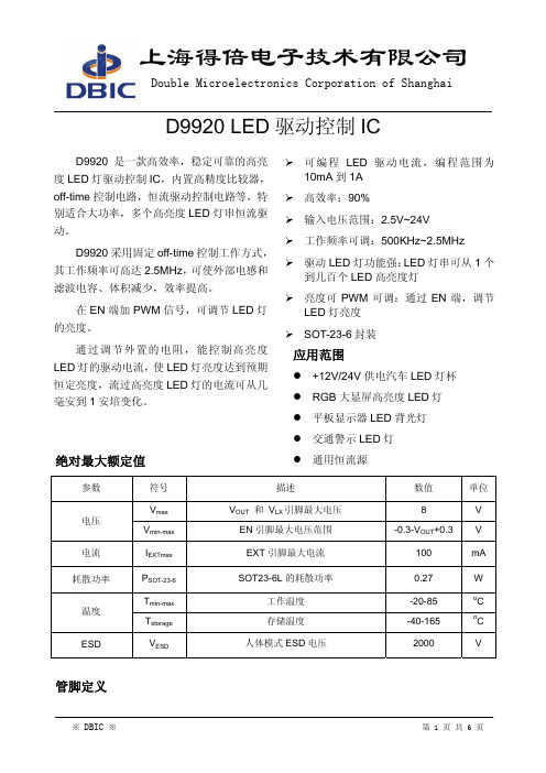
D9920 是一款高效率,稳定可靠的高亮 度 LED 灯驱动控制 IC,内置高精度比较器, off-time 控制电路,恒流驱动控制电路等,特 别适合大功率,多个高亮度 LED 灯串恒流驱 动。
min
max
0.031
0.057
0.006
0.055
0.071
0.010
0.022
0.102
0.118
0.106
0.122
0.033
0.041
0.003
0.010
0.012
0.024
※ DBIC ※
第5页共6页
上海得倍电子技术有限公司
Double Microelectronics Corporation of Shanghai
SOT23-6L 封装尺寸
Symbol
A A1 B b C D E H L
Dimension(in mm)
min
max
0.787
1.450
0.152
1.397
1.803
0.250
0.559
2.591
2.997
2.692
3.099
0.838
1.041
0.080
0.254
0.300
0.610
Dimension(in Inch)
如果不外接 ROFF 和 COFF,D9920 内部将关断时间设定为: TOFF = 612ns
Leds 的电流由 Rcs 设定为: ILEDs = 250mV Rcs
- 1、下载文档前请自行甄别文档内容的完整性,平台不提供额外的编辑、内容补充、找答案等附加服务。
- 2、"仅部分预览"的文档,不可在线预览部分如存在完整性等问题,可反馈申请退款(可完整预览的文档不适用该条件!)。
- 3、如文档侵犯您的权益,请联系客服反馈,我们会尽快为您处理(人工客服工作时间:9:00-18:30)。
玻璃纤维(增强的热固树脂玻璃纤维)管及配件用静水压、压力设计基础应用标准1.应用范围1.1 为了得到玻璃纤维管的静水压设计基数(HDB)或压力设计基数(PDB),该规定确立了2个规程:规程A(循环的)和规程B(静态的)。
这些基数是从强力回归实验数据中得到的。
强力回归实验所用材料为相同材料和结构的管道或配件或者上述两者,可以分别取样也可以在配套取样。
增强玻璃纤维热固树脂(RTRP)和增强玻璃纤维聚合砂浆管(RPMP)都属于玻璃纤维管。
1.2 该规定可以适用于玻璃纤维管HDB的确定,玻璃纤维管的外径和壁厚的比之要大于10:1.1.3 该规定提供了形状复杂产品或由于复杂应力场的存在严重阻碍了环向应力使用的系统的PDB。
1.4 试验中所用的末端封闭的样品可能是受控端也可能是自由端,可能导致某些限制。
1.4.1 受控端—样品只受到内部压力的环向应力,HDB可以适用于仅由环向产生的应力。
1.4.2 自由端—样品受到内部压力的环向和纵向应力,环向应力是纵向应力的两倍。
该规定不适用于评价由于负荷引起的应力,其中负荷压力超过了HDS的50%.1.5 数据所用的单位以英尺-英镑作为标准单位。
括号中的数据仅作为信息提供。
1.6 该标准没有说明相关的安全问题,如果有安全问题,请结合使用。
该标准的使用者应该建立适当的安全和健康规范,并且在使用之前确定局限的适用性。
2. 参考文献2.1 ASTM 标准:D 618 Practice for Conditioning Plastics for Testing3D 883 Terminology Relating to Plastics3D 1598 Test Method for Time-to-Failure of Plastic Pipe Under Constant Internal Pressure4D 1599 Test Method for Short-Time Hydraulic Failure Pressure of Plastic Pipe, Tubing, and Fittings4D 1600 Terminology for Abbreviated Terms Relating to Plastics3D 2143 Test Method for Cyclic Pressure Strength of Reinforced ThermosettingPlastic Pipe4D 3567 Practice for Determining Dimensions of “Fiberglass”(Glass–Fiber–Reinforced Thermosetting Resin) Pipe and Fittings4F 412 Terminology Relating to Plastic Piping Systems4F 948 Test Method for Time-to-Failure of Plastic Piping Systems and Components Under Constant Internal Pressure with Flow2.2 ISO 标准3. 术语3.1 定义3.1.1 概述—定义是与术语D883和F412一致的,缩写与D1600术语一致,除非有其他说明。
3.1.2 闭合、自由端—固定到测试样品的末端可以产生除环向和辐射应力以外的纵向拉力的密闭的装置或设备。
3.1.3闭合固定端—一种固定到穿过测试样品或通过测试样品外部结构杆上的密闭装置或设备。
可以抵抗由于内部应力产生的末端推力,限制样品的压力仅限于环向和辐射应力。
3.1.4 失败—是指测试液体通过被测样品时,从末端起,超过一米长的距离出现一下状况时,称为失败:管壁断裂,局部漏水或者渗漏。
3.1.5 玻璃纤维管—玻璃纤维管为管状产品,包含通过热固树脂固化植入的或缠绕的玻璃纤维增强层。
其组成结构包括粒状或板状的填充物、触变剂、染料、热塑性塑料、热固性衬里、涂料等。
3.1.6 增强聚合物砂浆管—添加混凝料的玻璃纤维管3.1.7 增强热固树脂管—不添加混凝料的玻璃纤维管3.1.8 环向应力—由于内部压力产生的管壁的拉伸应力。
环向应力可以由ISO公式计算。
公式如下:S=P(D-t r)/2 t r其中S=环向压力,帕斯卡(kPa)D=平均增强层外径,英尺(mm)P=内部压力,psig(kPa)t r=最小增强层壁厚,英尺(mm)3.1.9 静水压设计基数(HDB)--在该规范中,静水压设计基数即为用于玻璃纤维管的环向应力。
该环向压力乘以一个辅助设计参数就可以得到HDS。
3.1.10 静水压设计压力—是指估计的最大内部静水压。
该水压可以把循环的(规程A)或连续的(规程B)用于具有高确定性的管道组件。
这样可以保证不会出现组件失效的现象。
3.1.11 静水压设计应力—指估计的环向管壁最大拉伸应力。
该应力是由于内部静水压力产生的,该水压可以把循环的(规程A)或连续的(规程B)用于具有高确定性的管道组件。
这样可以保证不会出现组件失效的现象。
3.1.12 长期静水压强度(LTHS)--指估计的环向管壁拉伸应力。
该应力是由于内部静水压力产生的,当该应力按照规程A循环应用达到一定循环次数或按照规程B循环使用一定小时数后,将会导致管道失效。
3.1.13 长期静水压力(LTHP)--指估计的管道的内部压力,当该应力按照规程A 循环应用达到一定循环次数或按照规程B循环使用一定小时数后,将会导致管道失效。
3.1.14 压力设计基数(PDB)—该基数为内部压力,用于管道产品。
同时乘以一个辅助设计参数就可以得到HDP。
3.1.15 压力等级(PR)--指估计的管道或配件的最大压力。
该压力可以连续施加并保证管道组件不会失效。
3.1.16 辅助设计参数—该参数是为1,或者小于1的一个数值。
在管道安装中,考虑由于安全等级引起的变量。
如果该参数乘以HDB,可以得到HDS和与之对应的压力等级。
或者,当该参数乘以PDB的时候,可以直接得到压力等级。
这样可以得到优质的管道组件以及安装效果。
3.2 该标准相关的特殊词汇定义3.2.1 平均外径—该尺寸按照D3567标准进行测量。
该尺寸小于纱增强和未增强外表面覆盖厚度。
3.2.2最小增强壁厚--该尺寸按照D3567标准进行测量,不包括纱增强和未增强覆层厚度和衬里厚度。
配件的壁厚在最薄的部分进行测量。
4. 规章总结4.1 规程A规定将18个管道或配件样品置于内部周期循环压力的环境,其循环速率未25周/分,并且改变不同的压力。
改进测试温度0可以通过循环样品内部的热流体或者在可控温的空气环境中进行测试。
4.1.1 管道或配件的循环LTHS或循环LTHP是通过外推法得到的。
外推法是以log-log为坐标的线性回归直线,坐标为环向应力或内部压力与失效周期。
4.1.2 规程A的实验基础应与D2143测试方法一致,该实验基础未本方法的一个组成部分,如果操作过程的任何一个部分不符合D2143,应对其进行调整。
4.1.3管道和配件间的接头应当为应用于测试完成的管道的常见接头种类。
4.2 规程B:将至少18种管道或者配件置于恒定的内部静水压力中,改变压力等级,并测量每个压力条件下的失效次数。
测量温度可以通过将样品浸入到控温水浴中得到,或通过测试空气温度(空气温度是可受控制的),或通过在样品周围循环一定温度的液体。
4.2.1 管道或配件的LTHS或LTHP数据可以由外推法得到。
外推法是以log-log为坐标的线性回归直线,坐标为环向应力或内部压力与失效周期。
4.2.2 规程B的实验基础应与D1598测试方法或F948方法一致,该实验基础未本方法的一个组成部分,如果操作过程的任何一个部分不符合D2143,应对其进行调整。
4.2.3 管道和配件间的接头应当为应用于测试完成的管道的常见接头种类。
4.3 HDB种类是通过按照第7、10部分将LTHS分类得到的。
4.4 PDB种类是通过按照第8、11部分将LTHP分类得到的。
4.5 管道的静水设计应力通过HDB值与辅助设计参数相乘得到。
4.6 更改HDB或PDB时的确认工作说明—按照本规定,如果一个产品已经有了相应的HDB或PDB,要对工艺或是材料进行更改时,可以按照第12部分,再确认原始的HDB或PDB。
至少应该测试6个样品并且样品都符合标准要求。
5. 重要性及应用5.1 该规定有助于确定环向应力或内部压力与失效时间的关系,在选定的内部和外部条件下(该条件为模拟产品最终使用时的环境),可以获得管道产品和材料的设计基数。
该标准为直线型、中空圆柱形的材料定义了HDB,这种材料的环向压力可以很容易地计算出来。
同时,也对应力更加复杂的配件和接头定义了PDB。
5.1.1 该标准还定义了取代应力基数HDB的张力基数HDB。
该基数是通过初始张力和失效时间的关系来确定的。
张力基数HDB应用于地脉式管道,其内部压力范围为0-250psig(1.72Mpa)。
5.2 为了对玻璃纤维管道进行表征,有必要建立应力与循环次数或失效时间、压力与循环次数或失效时间的关系,在控制的环境参数范围内,时间应当大于3或以10为底的对数。
由于实验的性质和所用样品的性质,没有单一的直线可以充分代表实验数据,因此应建立置信度。
5.3 不同温度下,对于不同规格的管道的压力等级可以由HDS来确定,通过测试一种尺寸的管道的压力等级,其同样的测试过程和材料可以用于测试样品和有问题的管道。
5.4 对于不同温度下,除直线中空形管道之外的的组件的压力等级可以由HDP来确定:通过测试一种尺寸的管道的压力等级,其同样的测试过程和材料可以用于测试组件。
对于接头,用于准备测试样品的连接材料和过程应用于接头安装。
缩放比例和关键尺寸与直径和压力等级有关。
5.5 在一个环境条件下所得到的实验结果不能用于其它条件,除非更高温度的数据可以用于低温设计基数。
设计基数应当由每个管道产品来确定。
设计和生产过程会影响管道的长期性能,因此在任何评价中,都应考虑设计和生产过程。
5.6 该标准只对指定的管道和配件有效,因此样品要真实代表材料和生产过程。
5.6.1 如果材料和生产过程发生了变化,那么要再进行评价,方法如第12部分。
规程A6 长期循环静压强度或长期循环静压6.1 基于由内部压力产生的拉伸应力和管道系统的链接方式选择自由端或限制端的封头。
6.2 根据测试方法D2143,在选定温度下,获取至少18个最小失效应力-循环点,以下情况除外:6.2.1 按照方法D3567,确定平均外径和最小增强壁厚.6.2.2 高温测试温度是通过在样品周围循环加热的测试液体或者通过在热空气环境中进行测试。