浪涌保护器说明书
德力西电气 CDYN浪涌保护器产品样本 产品说明书

CDYN系列电涌保护器CDYNSCB系列电涌保护器专用保护装置产品样本北京办事处北区中区地址:北京市丰台区枫竹苑一区(未来假日花园)18-10 邮编:100076天津办公点地址:天津市西青区凯安道凯信佳园9-3-401邮编:300100沈阳办公点地址:辽宁省沈阳市于洪区细河南路碧桂园银河城钻石郡148-3邮编:110000长沙办公点地址:湖南长沙市芙蓉区万象企业公馆5栋2709邮编:410000郑州办公点地址:河南郑州金水区青年路145号6号楼17层1706号邮编:450000武汉办公点地址:湖北武汉市江汉区新华路186号福星国际商会大厦2516、2517室邮编:430000温州办公点地址:浙江省乐清市柳市镇德力西工业园邮编:325604成都办公点地址:成都市金牛区人民北路二段118号金牛万达广场甲级C座 16楼1603号邮编:610000南京办公点地址:江苏省南京市秦淮区洪武路23号隆盛大厦1505、1506室邮编:210000重庆办公点地址:重庆市九龙坡区渝洲路4号18-9号邮编:400039广州办事处地址:广州市荔湾区南岸路63号城启大厦1905室 邮编:510160南宁办公点地址:南宁市西乡塘区北大路中梦泽园小区岳阳阁5单元202室邮编:530003昆明办公点地址:昆明市西山区棕树营街道办事处土堆村碧鸡名城C地块9幢2802室邮编:650000贵阳办公点地址:贵阳市观山湖区石林东路中天帝景传说B区B4栋1单元1302室西安办事处地址:陕西西安市莲湖区大庆路三号蔚蓝国际A705 邮编:710082新疆办公点地址:新疆乌鲁木齐市米东区米东南路红光雅居D区6号楼3单元602室邮编:830000青岛办公点地址:青岛市城阳区正阳路177号15号楼2单元903室邮编:214000福建办公点地址:福州市晋安区东二环泰禾广场7号楼1117单元邮编:350024济南办公点地址:山东省济南市历下区工业南路55号未来城商务中心13#楼608室邮编:250000杭州办公点地址:杭州市江干区蓝桥景苑11幢2单元1002室邮编:310016南昌办公点地址:江西南昌市西湖区广场东路恒茂国际华城23幢2907邮编:330002深圳办公点地址:深圳市龙华新区民丰路1号碧水龙庭7栋4单元14D 邮编:518109兰州办公点地址:兰州市城关区瑞德摩尔万国港E座2208邮编:730020电话:153****1522合肥办公点地址:安徽省合肥市瑶海区武里山路五里山天街3A-1402室邮编:230000吉林办公点地址:吉林省长春市经开区浦东路与深圳街交汇处虹湾国际A座706室邮编:130031黑龙江办公点地址:黑龙江省哈尔滨市道外区润达国际D座2单807室邮编:150050石家庄办公点地址:石家庄市裕华区华兴生活小区41-1-102邮编:050011太原办公点地址:山西太原市万柏林区西矿街70号红星小区五单元1402邮编:030024石家庄物流地址:河北省石家庄市元氏县殷村石武铁路东国达物流园内电话:155****1257辽宁物流地址:沈阳市苏家屯区雪莲街188号(雪莲街与四环路交叉口)华翔东北亚贸城 D1 德力西陕西物流地址:陕西省西安市六村堡丰产路西段陕西商储物流园南区B1号德力西仓库山东物流地址:山东省临沂市经济技术开发区翔宇路23号华派克物流园内 重庆物流地址:重庆市江津区珞璜工业园B区重庆西部诚通物流有限公司5号库成都物流地址:四川省成都市青白江区国际集装箱物流园区德汇路9号4栋4-4号广东物流地址:广东省佛山市南海区里水镇怡和二路银裕木业制品厂直入100米河南物流地址:河南省郑州市经济开发区国际物流园喜达路宇培物流园(礼通路)东北W4-A区4B 58-59号湖北物流地址:湖北省武汉市东西湖区临空港大道23号捷利物流园3号库温州物流地址:浙江省乐清市柳市镇德力西高科技生态工业园新疆物流地址:乌鲁木齐市友谊路230号(新疆诚通国际物流园内德力西仓库)芜湖物流地址:安徽省芜湖市芜湖县新芜经济开发区朝阳路德力西物流中心产品介绍电涌保护器基础知识产品介绍技术参数SPD 常用名词解释怎样看电涌保护器的好坏?它有些什么主要技术参数,各有什么重要性?为什么电涌保护器需要后备保护装置?电涌保护器的后备保护装置需要满足那些要求?不同接地系统SPD 极数的选择Ⅰ类实验 (Class I test)用标称放电电流In 、1.2/50冲击电压和最大冲击电流Iimp 做的试验。
瑞科电气 HBCR 系列浪涌保护器安装手册说明书

INSIDE FRONT COVER(Blank)CONTENTSPage1. Warnings ... ... ... ... ... ... ... ... ... ... (4)2. Introduction ... ... ... ... ... ... ... ... ... (5)3. Protection Concepts.. ... ... ... ... ... ... (7)4. Mounting and Cautions... ... ... ... ... (9)5. Voltage Ratings.. ... ... ... ... ... ... ... (10)6. Protection Mode.. ... ... ... ... ... ... ... (13)7. Connection Method ... ... ... ... ... ... (15)8. RCD, ELCB... ... ... ... ... ... ... ... ... (20)Page9. Isolation and Fusing... ... ... ... ... ... (20)10. Status Indication and Alarms... ... (22)11. MPM, Movtec Protection Module ... (24)12. Maintenance and Testing.. ... ... ... (27)13. Extended Warranty... ... ... ... ... ... (28)14. Six Point Plan... ... ... ... ... ... ... (29)15. Use of Mimic Panels... ... ... ... ... (30)1. WARNINGS•Prior to installation ensure that the Movtec is of the correct voltage andfrequency, and is the type recommended for the local power distribution, and for theequipment being protected.•Hazardous voltages may exist internally to the units. The units should be installed(and replaced) only by qualified personnel in accordance with all relevant Electricity Safety Standards.•Do not power MPMs and three phase connected Movtecs (Ph-N) without theupstream neutral connected. Failure to do so may damage the Movtecs and/or theload.•Where the MPMs/Movtecs are connected to an earth, this must be a low impedance earth (<10 Ω) for correct operation.•X1-X4 connections may be at phase voltages dependant upon connection method.•If connecting to the Movtec alarm outputs do not exceed the maximum permissibleratings as damage may occur.•Movtecs must be installed in anenclosure or panel, ensure this does notcause their environmental ratings to beexceeded.•Do not “Megger” or “Flash Test” circuits with Movtecs installed.•The DINLINE Surge Counter (DSC) should not be used in voltage sensing mode withTDS-Movtecs. Voltage sensing mode is not compatible with TDS-Movtecs.•All instructions must be followed to ensure correct and safe operation.•Diagrams are illustrative only, and should not be relied on in isolation.2. INTRODUCTIONMovtecs are designed to protect mains powered equipment from the damaging effects of lightning and transients. They are ideal for point-of-entry shunt protection applications where robustness and high surge ratings are required.The Movtec family is designed to suit many distribution systems including TN-C, TN-S, TN-C-S and TT. They can be selected for use with distribution systems with nominal voltages of 110/120V, 220/240V and 277Vrms at frequencies of 50/60 Hz.The TDS Technology (Transient Discriminating Suppressor) units are specifically designed for distribution systems that may feature poor voltage regulation where the actual supply voltage may exceed the nominal ratings for extended periods.This Installation Manual details the preferred procedure for the installation of the family of Critec Movtec™ Surge Diverters.The Critec Movtec family includes:•Critec Movtec, Single Mode, enhanced MOV technology units eg. (MT275V-135K-A)•Critec TDS-Movtec, Single Mode, TDS technology unit featuring high over-voltage withstand for added robustness (TDS-MT-277)•Critec TDS-Movtec, Three Mode, TDS technology unit featuring high over-voltage withstand for added robustness (TDS-MTU) TDS-Movtec units are coloured blue for easy identification, while enhanced MOV technology units are coloured red.In this manual, reference to “ Movtec” also includes “TDS-Movtec”.4. MOUNTING & CAUTIONSThe performance of surge diverters can be dramatically affected by the method of connection (refer section 7). Where possible select a mounting method that allows the Movtec to be connected in the “Preferred Connection Method”.Failure of a Movtec under severe AC over-voltage, such as 11kV on 240V mains, can result in the generation of significant heat. Consideration should be given to ensure that Movtecs are not installed in close proximity to combustible materials.Units must be installed in an enclosure or panel to provide the appropriate degree of electrical and environmental protection.Only use enclosures that:•Do not cause the Movtec temperature to exceed 60 deg C•Provide adequate electrical and safety protection•Prevent the ingress of moisture and water •Allow Movtec Status Indication to be inspected5 VOLTAGE RATINGSThe TDS (Transient Discriminating Suppressor) technology has been specifically developed to cater for abnormal over-voltage conditions that may occur on sites with poor voltage regulation, or due to wiring or distribution faults. The TDS units feature an extremely high over-voltage withstand to eliminate heat build up that can occur with standard technologies when the protection devices start to clamp on the peak of each abnormal mains cycle.Traditional MOV technology (eg MT-275V/ 135K/A) is not suitable in applications where sustained over-voltage conditions can be experienced.Examples of poorly regulated voltage environments include:•Smaller power generation supplies•Sites with large earth currents•Variable motor speed control circuits •High harmonic voltage environments (non-linear loads)The TDS range of Movtecs with a higher over-voltage withstand may be able to be used in these environments following advice.Transient protection devices are usually rated to protect against non-repetitive pulses from such sources as direct or induced lightning strikes. They are not designed to provide protection against repeated cyclic anomalies. Nor are they designed to provide protectionagainst sustained over-voltage conditions where the supply voltage exceeds the protection equipment’s nominal rating for an extended period of time, ie continuous over-voltages from poorly regulated generators or distribution systems.Smaller power generation equipment (particularly capacitive excitation induction generators) does not generally conform to the same standards of voltage regulation that are in place for mains power reticulation. A large number of smaller and/or cheaper generators have a voltage waveform that is “loosely”240Vrms (often poorly regulated), but more importantly, often contains significant higher order harmonics. These generators may exhibit a peak voltage on each half cycle far in excess of the normal 340V. The problem is usually worse when the generator is lightly loaded.Whilst electrical equipment may tolerate this over-voltage for a period of time, the clamping elements in the power protection devices will begin to conduct on the peak of each 50Hz cycle, as their voltage threshold is reached (typically 400V peak for a traditional 275V diverter). This will cause slow degradation and ultimate failure of the clamping device (time dependent upon how poor the waveform is).Harmonic voltages may also be present in distribution systems that do not feature generators. This is normally where non-linear loads are used, such as UPSs, rectifiers, switch mode power supplies and motor speed controls. The high harmonic voltages in certain applications may have peak voltages in excess of the protective clamping voltage causing problems as described above. Seek the manufacturer’s advice before installing anyproduct into a circuit which features a total harmonic voltage ratio above 5%.Ensure that the correct voltage rating unit is installed. Exceeding the nominal rating while transient events occur may affect product life.†Note: Other voltage rating Movtecs are available. Refer to Movtec table for actual ratings.6. PROTECTION MODESMovtecs are available in Three Mode and Single Mode configurations. This refers to how the internal protection is arranged and applied to the circuit to be protected.Three Mode units provide protection between the Phase-Neutral*, Phase-Earth* and Neutral-Earth circuit within one Movtec. Single Mode units provide protection between two conductors connected to the terminals marked T1 and T2. These units can be connected to provide protection from Phase-Neutral* or Phase-Earth* or Neutral-Earth. To allow the status indication and alarm circuitry to operate, a neutral connection is required for Phase-Earth* configured units, and a Phase* connection is required for*Note. Some users may be used to the terminology “Active” or “Line”, in place of“Phase”. For consistency “Phase” is usedthroughout this documentation.7. CONNECTION METHOD Array To optimise transient performance, attempt to connect the Movtecs in the “Preferred” fashion as depicted on pages 16 and 17. This is recommended for cable sizes between 6mm2 and 16mm2. Take care not to run the protected and unprotected wire parallel or in close proximity.Where this is not possible due to layout or conductor size, use the “Non-preferred” “T”connection method as depicted on pages 16 to 18. With this connection method, the “T” lead should be between 6mm2 and 16mm2. The connection should be as short as practicable (less than 100mm).Cable sizes less than 6mm2 should not be usedwithout specialist advice.8. RCD, ELCBWhere RCDs/ELCBs (Residual Current Devices / Earth Leakage Circuit Breakers) are fitted the Movtecs should be installed in the circuit prior to these devices (ie upstream). Where this can not be avoided and RCDs/ ELCBs are installed upstream, nuisance tripping of the RCD/ELCB may occur during transient activity.Contact your local ERICO agent for advice if upstream RCDs/ELCBs can not be avoided. 9. ISOLATION AND FUSING Overcurrent and short circuit protection must be provided to protect the Movtec and associated wiring if a fault develops. The overcurrent protection should be installed in such a manner to also provide a means of isolating the Movtec module from the mains supply. This is an important safety consideration and is required in the event that any future maintenance or testing is needed. The Movtec uses disconnection devices to isolate internal segments that have reached the end of their service life. In order for this disconnection to occur correctly, Movtecs should be only used on circuits with fuse or circuit breaker ratings of 32A or greater. (Nuisance operation of the overcurrent protection may occur during transient activity on smaller capacity circuits.)On circuits with a capacity of greater than 100A, the Movtecs should be installed in series with a 100A HRC fuse being placed prior to the Movtec, as detailed in the diagram on page 21. This will require the Movtec to be installed in a similar manner to the non-preferred “T” connection method. Care must be taken to keep “T” connections as short and straight as possible. Note that this fuse may rupture under surge events exceeding 60kA, thereby disconnecting the protection circuit. Under such conditions it is important that suitable monitoring of the alarm contact should be carried out to detect this possible occurrence.10. STATUS INDICATION AND ALARMSA characteristic of all transient and surge protection devices is that they degrade in proportion to the magnitude and number of incident surges to which they have been subjected. Status indication should be periodically monitored to determine if replacement is required.Each Movtec features 5 protection segments. The status for each of these sectors is provided by way of a 5 segment LED bar graph. If any sector is damaged due to excess surge activity, a LED will extinguish. The LEDs extinguish in a sequential order (100% LED out first, 80% LED out next etc.) irrespective of which sector has sustained damage.of one of the three modes and that the TDS-Movtec unit should be replaced.Where multiple Movtecs are used, such as in three phase distribution systems the alarm contacts may simply be connected in series to provide a common alarm output connection.When mains voltage is applied to the fully functional Movtec, the alarm contacts will be closed . Should the surge handling capacity fall to below the alarm threshold, thesecontacts will open . The contacts are “fail-safe”in that, if power to the unit fails, the contacts will also revert to the open condition.For Single Mode units (TDS-MT-277 and MT275V-135K-A)•The voltage free alarm contacts are activated (opened) as soon as the primary protection status displays 60% or less and indicates that the Movtec unit should be replaced.For Three Mode units (TDS-MTU)•The voltage-free alarm contacts are activated (opened) as soon as the protection status displays 80% or less. This indicates thatdamage has been sustained to the protection11. MPM, MOVTEC PROTECTION MODULEThe MPM utilises a high energy Neutral to Earth spark gap to provide robust protection against earth potential rise problems. Care is required to ensure co-ordination of this device if any other voltage limiting device is connected either upstream or downstream in the Neutral to Earth circuit. Contact your local agent for further information if other N-E protection devices are installed and co-ordination may be affected.INSTALLATION PROCEDURE FOR MPM1.Remove the cover from the MPM.2.Select the MPM mounting position to ensureoptimum electrical connection method (refer Section 7) and in accordance with all giveninstructions.3.Position and mark the mounting position ofthe MPM on the wall.4.Depending on the mounting surface, preparesuitable anchoring holes for the markedposition.5.Snap the mounting spacers, supplied, intothe rear of the back of the MPM as shownin Figure 1. (see inside back cover P31)6.Mount the unit to the wall. To ensure theIP33 rating is preserved, the MPM shouldbe mounted to the wall using the spacersprovided and one of the fixing methods asshown in Figure 1. (see inside back cover P31)7.Prepare the appropriate cable glands. It isrecommended that a nylon cable gland(typically rated at IP66) be used.8.Install wiring, taking care to support cablingdirectly connecting to the MPM unit, andtighten all terminals.9.Check that the MPM is installed in accord-ance with all instructions, and relevantelectrical safety codes.10.Replace MPM cover, then apply power.11.Correct operation of the MPM unit is estab-lished by checking that all 5 LED’s on each MOVTEC bar graph are lit, and that power is correctly being supplied to the load(s). INSTALLATION ARRANGEMENT FOR AUSTRALIAN MEN SYSTEMSUnder Australian Standards classification, MPMs are considered a piece of equipment tobe connected to the mains Array supply. The MPMs are not intended for use as, nor are they, a ‘switch board’,‘distribution board’ or other equipment. As MPMs are classified as ‘electrical equipment’ (ie: a product), AS 3000 Wiring Regulations apply to the installation and operation of the units.In the multiple earth neutral (MEN) distribution system, the MPM equipment should be installed as close as possible after the MEN point and after both the main disconnect switch/ overcurrent protector andany metering equipment.12. MAINTENANCE & TESTING Before removing any unit from service ensure that power to the device is isolated. Replacement of any Movtecunits should only be undertaken in accordance with all relevant Electricity and Safety Standards by suitablyqualified personnel.Movtecs should be inspected periodically, and also following any periods of lightning or transient activity. Check the status indicators and replace if in the “Alarm” condition as detailed in Section 10 -STATUS INDICATION. For high transient exposure sites or those of a critical operational nature, it is recommended that the alarm outputs be monitored to provide an additional warning of reduced capacity (refer Section 10).Movtecs are designed for optimum performance under severe transient activity. To provide this performance, electronic components in the Movtec are encased in a patented proprietary, shock and thermal absorbant compound. Units cannot be serviced, they must be replaced.Do not attempt to open or tamper with the units in any way as this may compromise performance and will void warranty.Do not “Megger” or perform other types of electrical tests that apply voltages greater than the nominal operating voltage of the Movtec. The Movtec will attempt to limit these voltages thereby affecting the test result. Where these tests must be performed, remove the Movtec from circuit first.13. EXTENDED WARRANTYThis product has a limited warranty to be free from defects in materials and workmanship for a period of five (5) years from the date of dispatch from the Manufacturer. The Purchaser acknowledges that lightning is a natural event with statistical variation in behaviour and energy levels which may exceed product ratings, and 100 % protection is not offered and cannot be provided for. Therefore the Manufacturer’s liability is limited to the repair or replacement of the product (at the Manufacturer’s sole option) which in its judgement has not been abused, misused, interfered with by any person not authorised by the Manufacturer, or exposed to energy or transient levels exceeding the Manufacturer’s specifications for the product. The product must be installed and earthed (where applicable) in strict accordance with the Manufacturer’s specifications and all relevant national Electricity and Safety Standards. The Manufacturer and the Purchaser mutually acknowledge that the product, by its nature, may be subject to degradation as a consequence of the number and severity of surges and transients that it experiences in normal use, and that this warranty excludes such gradual or sudden degradation. This warranty does not indemnify the Purchaser of the product for any consequential claim for damages or loss of operations or service or profits. Customers should contact their nearest manufacturer’s agent to obtain a Product Repair Authorisation Number prior to making any claim under this warranty. This is only a summary of the warranty given by the Manufacturer. The full text of the warranty is set out in the Manufacturer’s Conditions of Quotation and Sale. The above limited warranty is additional to rights which arise in respect of the sale of industrial and technical products and services to knowledgable buyers under the Australian Trade Practices Act 1974 as amended.loops anddifferentialsProtect equipmentthrough a lowimpedance earthsystem15. USE OF MIMIC PANELSMovtecs are used in the Proline range of Surge Reduction Filters where superiorprotection is required for critical or sensitive electronic equipment. Some models of SRF use an electronic mimic panel to display in thefront door the status of the internal Movtecs.The X1-X4 terminals on the Movtec are used for this purpose. If this Movtec is to be used with a mimic panel (possibly as a replacement for an existing Movtec in a SRF) please ensure compatibility as below.Figure 1. MPM mounting spacers.。
浪涌保护器的使用方法
浪涌保护器的使用方法嘿,朋友们!今天咱来聊聊浪涌保护器这玩意儿的使用方法。
这东西啊,就像是家里电器的小保镖!你想啊,电就像个调皮的小孩子,有时候会突然发脾气,来个大波动,这要是没个保护的,咱那些宝贝电器可不得遭殃啊!浪涌保护器就是专门来对付这种情况的。
那怎么用它呢?首先得选对地方安装。
就好比你给花找个合适的花盆一样,得放在能发挥它最大作用的地方。
一般来说,就在配电箱里给它安个家。
安装的时候可别马马虎虎的,得拧紧螺丝,让它稳稳当当的待在那。
然后呢,要定期检查检查它。
这就跟咱人得时不时去体检一样。
看看它有没有啥毛病,指示灯是不是正常亮着呀。
要是发现有啥不对劲,赶紧处理,可别拖着。
你说要是它坏了不工作了,那不就等于保镖失职了嘛,那咱的电器还不得提心吊胆的。
还有啊,可别以为装上浪涌保护器就万事大吉了。
咱平时用电也得注意点,别啥大功率电器都一股脑插上,那也容易出问题呀。
就像你让一个人干太多活,他也会累垮的呀。
而且啊,这浪涌保护器也不是能一直保护下去的,它也是有寿命的哟!就像咱的鞋子,穿久了总会磨损的嘛。
所以到了一定时候,就得给它换换啦。
你想想,要是一直穿着破了的鞋子走路,多不舒服呀,同理,一直用着过期的浪涌保护器,能让人放心吗?咱再打个比方,浪涌保护器就像是一道坚固的城墙,把那些乱七八糟的电涌都给挡在外面,保护着城里的电器们。
要是这城墙不牢固了,那还怎么保护呢?所以啊,大家可一定要重视它的使用和维护哦!总之,浪涌保护器虽然看着不起眼,但作用可大着呢!咱可不能小瞧了它。
好好对待它,让它好好为咱的电器服务,这样咱才能安心地享受各种电器带来的便利呀,对吧?大家可一定要记住这些使用方法哦,别不当回事儿!。
浪涌保护器 CSNB-80 系列说明书
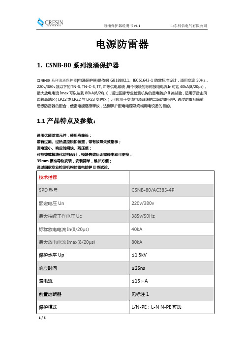
1.1 产品特点及参数:
选用优质防雷元件,使用寿命长; 带有过流、过热温控脱扣装置,带有故障失效指示; 漏电流小、响应时间快、残压低; 可插拔式模块化结构设计,模块失效后无需停电即可更换; 35mm 标准导轨安装,安装简单,维护方便; 通过国家专业检测机构的雷电防护 II 类试验。
技术指标
SPD 型号
保护模式:L/N-PE接线示意图
L1 L2 L3 N PE
交
N
流
空
气
开
关
3/5
浪涌保护器说明书 v1.1
山东科信电气有限公司
保护模式:L-N N-PE接线示意图
L1 L2 L3 N PE
交
流
空 气 开
Surge Protective De v ice
N-PE
关
NN N N
1.3 浪涌保护器原理图
4/5
16mm2 25 mm2 端子接线 可选 可选 有(有效:绿--失效:红) 1P、2P、3P、4P 可选
AC220v/380v TN-S/三相五线
阻燃性塑料外壳 108x90x62(mm) 35mm 标准导轨安装
-40℃~+80℃ -40℃~+80℃ 5~95%(无凝露) IP20 不超过 3000m
设计标准 接口 接入导线截面 接入接地线导线截面 接线方式 遥信接点 报警接点 脱离器动作指示 极数 电源 适用电源 电源系统 机械特性 外壳材料 尺 寸(W×H×D) 安装方式 工作环境 操作温度 存储温度 相对湿度 防护等级 海拔高度
2/5
浪涌保护器说明书 v1.1
GB18802.1
山东科信电气有限公司
CSNB-80/AC385-4P
额定电压 Un
浪涌保护器使用说明书

᱂ܝ⇨ϴЏԧᓔথഄ☦▊ṗᎹ࣏☿⇨☿⇨᪂᪂07/⌾⍠⌾⍠ֱᡸ఼ֱᡸ఼ֱᡸ఼ՓϬՓϬՓϬ᪸ᯢк᪸ᯢк᮴⏥᮴⏥ṙᗱᅝṙᗱᅝṙᗱᅝᅝܼᅝܼᅝܼ᪂᪂᪂᳝└᳝└᳝└݀ৌ݀ৌT h e S L P S e r i e s is a range of surge protec-tion devices combining high packing densi-ties, application versatility, proven hybrid cir-cuitry and simple installation -- features which make the series the most cost effec-tive surge protection solution for process control equipment systems and communica-tions networks.T h e m u l t i -s t a g e h y b r i d s u r g e p r o t e c t i o n n e t -w o r k at the heart of the SLP uses a combi-nation of solid state electronics and a gas filled discharge tube (GDT) to provide surge protection up to 20kA. This impressive surge protection circuit is designed to exhibit exceptionally low line resistance and adds only a tiny voltage drop to the circuit.I n o p e r a t i o n , t h e S L P d e v i c e d o e s n o t a d v e r s e l y a f f e c t t h e p e r f o r m a n c e o r o p e r a -t i o n o f t h e l o o p or combined equipment. The device allows signals to pass with very little attenuation while diverting surge currents safely to ground and clamping output volt-ages to safe levels.F u l l y a u t o m a t i c i n o p e r a t i o n ,SLP devicesreact immediately to make sure thatequipment is never exposed to damagingsurges between lines or the lines andground. Reacting instantaneously, the SLPredirects surges safely to ground andthen resets automatically.T h e v e r s a t i l e S L P s e r i e s d e s i g n c o n s i d e r st h e n e e d f o r h i g h p a c k i n g d e n s i t i e s andhas a product combining protection fortwo process loops into one case. Eachmodule provides full hybrid surge protec-tion for two process loops.F o r h i g h e r b a n d w i d t h a p p l i c a t i o n s ,the SLPseries has been developed to meet thedemands of today’s highest speed com-munication systems.O n e s i m p l e m a n u a l o p e r a -t i o n clamps modulessecurely onto D I Nrail, which auto-matically provides the essential high-integrity ground connection.A 10 Y e a r ‘N o F u s s ’ w a r r a n t y is available as standard for the SLP so if a correctly connected device should fail for any rea-son, simply return it for a free replace-ment.‘T o p -h a t ’ (T -s e c t i o n ) D I N r a i l is generally suitable for mounting SLP modules although for adverse environments, a spe-cially-plated version is available from MTL Surge Technologies.Data & SignalProtectionUltra-slim user-friendly devices for protecting electronic equipment and systems against surges on signal and I/O cabling.G S u r g e p r o t e c t i o n f o r t w o l o o p s p e r S L P (o r o n e 4-w i r e c i r c u i t )G P l u g c o n n e c t o r s f o r q u i c k a n d e a s y c o n n e c t i o n o r r e w i r i n gG S p a c e -s a v i n g d e s i g n , 6m m w i d t h p e r l o o pG M u l t i -s t a g e h y b r i d p r o t e c t i o n c i r c u i t r y - 20k A m a x i m u m s u r g e c u r r e n tG R a n g e o f v o l t a g e r a t i n g s - t o s u i t a l l p r o c e s s I /O a p p l i c a t i o n sG D e s i g n e d f o r h i g h b a n d w i d t h , l o w r e s i s t a n c e a p p l i c a t i o n sSLP SeriesS p e c i f i c a t i o n All figures typical at 77°F (25°C) unless otherwise statedM a x i m u m s u r g e c u r r e n t 20kA (8/20μs waveform) per line L e a k a g e C u r r e n t <1μA @ working voltage M a x i m u m r a t e d l o a d c u r r e n t1.50A L o o p r e s i s t a n c e 2 OhmC a p a c i t a n c eLine - Line - 60pFB a n d w i d t h-1db @9kHz - 37MHz-3dB @50MHzR e s p o n s e t i m e<1nsA m b i e n t t e m p e r a t u r e–40°F to +176°F (working)–40°C to +80°C (working)–40°F to +176°F (storage)–40°C to +80°C (storage)H u m i d i t y5 to 95% RH (non-condensing)T e r m i n a l s12 AWG (2.5mm 2)E l e c t r i c a l c o n n e c t i o n sPlug/header screw terminal strip M o u n t i n gT-section DIN-rail(35 x 15mm rail)W e i g h t5oz (140g approximately)Case flammabilityUL94 V-2E M C c o m p l i a n c eBS EN 60950:1992BS EN 61000-6-2:1999BS EN 61010-1:1993E l e c t r i c a l s a f e t yUL Isolated Loop Protector (Pending)Class I, Division 2, Groups A, B, C & Dhazardous locations (Pending)T o o r d e r s p e c i f y - Order by module, as listed in the specifi-cation table.Note: I n accordance with our policy of continuous improvement,we reserve the right to change the product’s specification withoutnotice.2 Installation Connection detailsR e vA09/16/04S t a n d a r d C e r t i f i c a t e /A p p r o v e d f o r P r。
帕顿510系列模块化浪涌保护器使用说明书
600 W for 1 mS
Response Time (RS-422): Clamped to + or - 6 volts after 0.5 µS,
200 Amps with a 8/20 µS pulse
Response Time (RS-232): Clamped to + or - 25 volts after 0.5 µS,
1.2 SERVICE
All warranty and non-warranty repairs must be returned freight prepaid and insured to Patton Electronics. All returns must have a Return Materials Authorization number on the outside of the shipping container. This number may be obtained from Patton Electronics Technical Service at (301) 975-1007. Packages received without an RMA number will not be accepted.
西泰尔光伏系统浪涌保护器使用说明书

SURGE PROTECTORSFORPhotovoltaic systemswww.citel.fr1221ROOF TOP INSTALLATIONSA professional approach to lightning and surge protection will guarantee your photovoltaic systems a long lifeSPD locationThe diagram below shows the pertinent locations for surge protectors as described in the CLC/TS61643-12 guide.Additional Surge ProtectorsIf the equipment to be protected (inverter or PV modules) is located more than 10 meters away from the initial surge protec-tor, the guide imposes the insertion of a complimentary surge protector to improve the level of protection.For low power PV applications, i.e. residences and small offices, it is necessary to consider surge protecting the AC output of the Inverter that connects directly into the electric power grid as well as the DC input side of the Inverter fed by the PV modules.AC Surge Protectorto protect all loads connected to the facility’s main distribution pa-nel against transients originating from the AC utility grid.AC networkAdditional AC Surge protectorIf the length of conductor between the PVinverter and the primary SPD in the main board exceeds 10 m, an additional SPD is necessary at the input of the inverter .Type 2 surge protectorDepending on the lightning rating of the installation area, a Type 2 surge protector on the DC network may be required.PV network AC network1222121121INDUSTRIAL AND PUBLIC BUILDINGSType 2 surge protectorIf the building is not equipped with a lightning rod system then a Type 2 surge protector is necessary or compulsory on the AC and DC inputs of the inverter . On the PV side, for cable lengths greater than 10 meters it is mandatory to install additional surge protectors at each end of the cable run.Type 1 surge protectorIf the installation is equipped with lightning rod systems, Type 1 surge protectors are compulsory at the AC input.The same on the DC side, Type 1 surge protectors are compul-sory in case of not isolated ligtning rod installation. Depending on the level of protection of the lightning rod, the total discharge current (Itotal) required can reach 20 kA.(See guide CLC / TS50539-12).Medium to large power PV systems can be installed on industrial and service facilities.In order to avoid very costly downtime and lost productivity resulting from a direct or indirect lightning strike, it is critical, and in some cases mandatory, to install surge protection at key points within your facility and its vital power and communication networks.AC networkType 2 AC surge protectorWhen the local lightning density is Ng > 2.5, by standard, it is mandatory to install an AC surge protector at the incoming service of the three phase network. In areas with a lower lightning density, while it is not mandatory, it is certainly good practice to install a surge protector for protection against switching transients originating from the external power grid not associated with lightning.Dataline Surge ProtectorsFor inverters connected to data networks(monitoring, control) or probes (luminous flux, temperature...), installation of relevant surge protectors is highly recommended.PV networkAC networkDatalinesAdditional AC Surge ProtectorDue to the long length of strings de-ployment, additional surge protectors are required near the PV modules. Installed generally in connection boxes.PV networkType 2 surge protectorDepending on the level of lightning strike in the installation area, a Type 2 SPD on the DC network at the in-verter input may be required. In the presence of non-isolated lightning rod, a Type 1 SPD is required.If the length of conductor between the PV inverter and the arrester in the MLVS ex-ceeds 10 m, an additional SPD is neces-sary at the input of the inverter.11111212PV POWER PLANTSType 1 surge protectorIf the PV field is equipped with lightning rod systems (rods, open air wiring…) Type 1 surge protectors are compulsory at the AC input.On the DC side, Type 1 surge protectors are compulsory at the inverters DC output as defined by CLC/TS 50539-12. Due to the long lengths of cabling required to connect numerous strings running throughout the PV farm, additional surge protectors are required at the input of the PV modules as well.PV power plants present a high risk of direct lightning impact and surges due to the large exposed area and the long lengths of the electric conductors.In order to avoid problems leading to costly damage and downtime, it is compulsory to install surge protectors at key points in the PV system.Type 1 DC Surge Protector panelDue to the long length of wires (>> 10 m), additional Type 1 SPDs are required at the input of PV modules. They are usually instal-led inside combiner boxes.AC Surge ProtectorType 1 surge protector is required at the AC network entrance whenever a light-ning rod is installed on the premises.Dataline Surge ProtectorsFor inverters connected to data networks (monitoring, control) or probes (luminous flux, temperature...), installation of relevant surge protectors is highly recommended.Type 1 DC Surge ProtectorDue to the risk of direct lightning strikes, Type 1 surge protector must be applied.AC network DatalinesPV networkPV networkDS60VGPV-1500G/51DS50PV-800G/51DLA-24D3DAC1-13-31-275 DAC40C-31-275DAC50-11-275 DAC40C-11-275DDC30C-20-65Head office FranceTél. : +33 1 41 23 50 23 e-mail:**************** Web : www.citel.fr FactoryReimsTél. : +33 3 26 85 74 00 e-mail:**************** Germany BochumTél. : +49 234 54 72 10 e-mail:************* Web : www.citel.deUSAMiramarTel : (954) 430 6310e-mail:*************Web site : ChinaSales departmentShanghaiTél. : +86 21 58 12 25 25e-mail:****************Web : FactoryTél. : +86 21 58 12 80 67RussiaMoscouTél. : +7 499 391 47 64e-mail:*************Web : www.citel.ruIndiaNew DelhiTél. : +91 11 2626 12 38e-mail:********************Web : www.citel.inThailandBangkokTél. : +66 (0) 2 104 9214Web : www.citel.frCITEL range DAC1-13DAC50DAC40C3-phaseDAC40C1-phase Surge protector Type 1+2Type 2Type 2Type 2AC network Un230 Vac230 Vac230 Vac230 Vac Max. AC operating voltage Uc255 Vac255 Vac255 Vac255 Vac Nom. discharge current (8/20µs)In20 kA20 kA20 kA20 kAMax. discharge current (8/20µs)Imax50 kA50 kA40 kA40 kAMax. lightning current (10/350µs)Iimp12.5 kA---Protection level Up 1.5/1.3 kV* 1.5/1.25 kV* 1.5/1.25 kV* 1.5/1.25 kV*P/N for single phase network DAC1-13-11-275DAC50-11-275-DAC40C-11-275 P/N for 3L+N network DAC1-13-31-275DAC50-31-275DAC40C-31-275-Télésignalisation de déconnexion OptionDAC1-13S-xx-xxxOptionDAC50S-xx-xxxOptionDAC40CS-xx-xxxOptionDAC40CS-xx-xxxDAC1-13 DAC50 DAC40C Type 1 and Type 2 Surge Protectors for AC power supply IEC61643-11 complianceDC SURGE PROTECTORS FOR PV OFF-GRID SITECITEL model DDC30C-20-65DDC40C-20-100DDC40C-20-180DDC40C-20-275DDC40C-20-460Network48 Vdc75 Vdc130 Vdc220 Vdc350 VdcMax.operating voltage Uc65 Vdc100 Vdc180 Vdc275 Vdc460 VdcNominal dischargecurrent (8/20µs)In15 kA20 kA20 kA20 kA20 kAProtection level Up300 V390 V620 V900 V1400 vRemote signalling OptionDDC30CS-20-65OptionDDC40CS-20-100OptionDDC40CS-20-180OptionDDC40CS-20-275OptionDDC40CS-20-460DDC30CDDC40C Type 2 Pluggable Surge Protector for PV Off-grid site- *) Common mode (L/PE or N/PE)/Differential mode (L/N)- Specific version DAC1-13VG and DAC50VG available: suppression of operating and leakage currents. SURGE PROTECTORS FOR AC NETWORK。
RES2 交流电浪涌保护器用户手册说明书
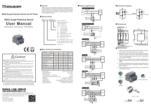
RES2 Surge Protective Device for AC PowerUser ManualRES2 Surge Protective DeviceThe company reserves the right to modify the product and changethe specification. If there is any update, it will be notified separately.RES2-20Series、RES2-40Series、RES2-80SeriesGeneral Typical applications Schematic diagramDimensionsMaintenanceNomenclatureMain technical parametersRES2 series AC power SPDs are designed according to the IECand GB standards. It enable the connection between the powersupply system and an equipotential network instantaneouslywhen the surge occurs and limits the residual voltage to a certainlevel to protect the devices.R E S2-X X-X X X X X-3none:F:w/o remote signalwith remote signalNumber of naught wireBlank means one naught wire2 means 2 naught wires3 means 3 naught wires1P:1G:2P:1PN1:3P:3PN1:4P:Single phase(MOV)Single phase(GDT)Single phase TNSingle Phase TT(with GDT)3phase 4wire, TN-C/IT3phase 4 wire, TT(with GDT)3phase 5 wire, TN-S20:Max. discharge current, Imax:20kA40:Max. discharge current, Imax:40kA80:Max. discharge current, Imax:80kASeries numberCheck the status indicator and replace the failed module orwhole product if the status indicator is not all green.Connect the terminal blocks of remote signal with solid orstranded conductor. The conductor section area is small than1.5mm2 and strip length is between 6 and 7mm. Tightened byscrew with 0.2 Nm torque.Before Power on, Make sure the connection tightened firmlybetween conductors and terminal blocks and grounding isreliable.The product undergoes rigorous inspection and quality controlbefore leaving the factory. If abnormal conditions are found,please contact us.5 years guarantee from the date of delivery, free replacementof malfunction products.Status indicator:Working temperature:Relative humidity:Housing protection level (IEC60529):Housing Material/flame-retarded level (UL94)Installation:Test Standards:Protection level:Certificate Authority:Remote signal output:Green : OK ; Red : Failed-40°C~+70°C5%~95%IP 20PA66/V0Standard 35 mm DIN railGB/T18802.1;IEC61643-11Surge Protection level , class II for PowerShanghai lighting protection center250VAC/0.5A;24VDC/0.5AModelParameterNominal operating voltage UnMax, operating voltage UcNominal discharge cur. In(8/20us)Max. discharge cur. In(8/20us)Protection level UpResponse timeLeakage currentMax. backup fuseConnection wire section area L/NConnection wire section area PERES2-20RES2-40220V AC320V AC10kA20kA1.2kV<25ns<20μA40A≥2.5mm²≥4mm²220V AC385V AC20kA40kA1.7kV<25ns<20μA80A≥4mm²≥6mm²RES2-80220V AC385V AC40kA80kA2.0kV<25ns<20μA125A≥4mm²≥6mm²RES2-80G-255V AC40kA80kA1.2kV<100ns--≥4mm²≥6mm²Single phase TN systemTN-S systemSingle phase TT systemGreen-OKRed-failedRemote Signal Output0.14 mm² - 1.5mm²No.388,Xingpu Mid RD,Shipu Business Adminstrcition Estate,Qiandeng Town,Kunshan City,Jiangsu Province,China邮编:215343TEL:+86-512-5708-8588FAX:+86-512-5708-8600E-mail:******************中国江苏省昆山市千灯镇石浦工商管理区兴浦中路388号(215343)1、2、3、4、5、18.0 mm2P/1PN136.0mm72.0mm4P/3PN1。