七星电子流量计 D08-1F-1FP-1FM
D08-1D-1K(2)质量流量计 使用手册
功能。可以通过后部接线端子的跳线,改变输入功能。 通常出厂时,显示仪接线为“内设”方式,见图 5a,将“设定”与“内设”线短路,通
11
-15V
12
-15V
13
14
公共地
15
+15V
1DM、1JM 型
5.4 1JM 型接线………………………………. 7
6.2 MFC/MFM 调零…………………………... 19
5.5 MFC/MFM 信号接线图…………………. 8
6.3 阀控开关…………………………………… 19
6. 操作方法…………………………………. 8
6.4 流量内设定信号…………………………… 19
a. “内设”接线图
信号地 电流输入
MFC
电流输出 信号地
信号地 电流设定 设定 内设 流量检测 阀控
地 ~85-265V ~85-265V
b. 内外“电压设定”转换接线图
信号地 电流设定 设定 内设 流量检测
外 内 设定转换开关
信号地
0~+5V D/A 转换器
c.“电流设定”
接线图
信号地 电流设定 设定 内设 流量检测
调零电位器
流量显示窗 流量单位指示
阀控开关
设定电位器
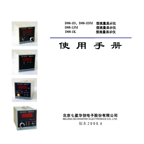
图 2. 1D、1DM 型流量显示仪外观
流量显示窗 显示选择开关
流量单位 调零电位器
报警指示灯
上限设定电位器
下限设定电位器
图 3. 1JM 型流量显示仪外观
利用傅立叶变换红外光谱法检测一氧化氮纯气中的氧化亚氮杂质_图.
18化学分析计量2008年, 第17卷, 第6期利用傅立叶变换红外光谱法检测一氧化氮3纯气中的氧化亚氮杂质王德发周泽义刘沂玲吴海盖良京(中国计量科学研究院, 北京100013摘要利用傅立叶变换红外光谱法对一氧化氮纯气中的氧化亚氮进行了定性和定量分析。
实验结果显示, 在恒定条件下进样, 分辨率为0. 5cm -1, 扫描512次, 选择2270~2130c m -1范围内的特征吸收进行定量分析时可以得到良好的分析结果。
利用双点法对氧化亚氮杂质进行定量计算, 并对分析结果进行了严格的不确定度评定, 为一氧化氮纯气中氧化亚氮的检测提供了一个全新的方法。
关键词傅立叶变换红外光谱法氧化亚氮杂质分析一氧化氮纯气是一种重要的工业气体, 可用于硝化生产和聚氯乙烯制备。
在电子工业中用于硅氧化膜形成氧化和气相沉积等, 以及用于航天和卫星的推进剂, 还可用于大气检测标准混合气体的制备、[1]大气环境检测和相关仪器的检定校准。
而不同的应用领域对一氧化氮纯度要求各不相同, 子工业和标准物质制备行业, 氧化氮气体, 、氧化亚氮、二氧化碳、氮气、。
虽然使用气相色谱法可以对其中某些杂质进行定量分析, 但是由于某些杂质具有很强的腐蚀性和反应活性, 对色谱分离系统的要求较高, 所以该方法有明显的局限性; 而且相对于不同的组分常常需要改变色谱条件, 甚至更换色谱柱, 操作繁琐。
有文献研究表明, 使用的校正标准与待测样品的介质不同也会导致分析上的很大误[2]差。
近年来, 傅立叶变换红外分析仪(FTI R 在气体分析中发挥了重要的作用, 在很短时间内便应用于各种气体分析和气体研究领域。
目前国际上很多研究机构都已经将傅立叶变换红外分析仪(FTI R 作为气体分析的工具。
它的优点在于:(1 检测响应时间短, 有利于对动态过程和瞬间变化的研究, 能够在线连续分析燃烧产生的烟气;(2 利用计算机储存和多次累加, 信噪比大大提高, 可以进行物质的痕量测定; (3 分辨率高, 可以同时对多种组分进行[3]定性定量分析。
流量计概述工作原理技术参数型号
F:4.0MPa G:5.0MPa H:6.3MPa I:10MPa J:11MPa
K:15MPa L:16MPa M:20MPa N:25MPa Q:25MPa
U:42MPa
介质温度 C:常温-20℃~+70℃ G:高低温196℃~+450℃
公称口径:为管道公称通径,单位为mm
介质类型:Y:液体 Q:气体 Z:蒸汽
4)工况压力下饱和水蒸汽流量测量范围表
闽制 00000188
----SBL 数显靶式流量计---
汇集传统精髓 再创顶尖科技
泉州日新流量仪器仪表有限公司
式中Qm,QV一-分别为质量流量和体积流量,kg/h,m3/h; α----流量系数;
D----测量管内径,mm
β----直径比 β=d/D
d----靶板直径,mm
其余符号同上。
靶板受力经力传感转换成电信号,经前置放大,AD转换及计算机处理后,可得到相应的流量和总量。其工作 原理图如下:
二次仪表显示
3.3 产品型号 3.3.1 型号含义
SBL □ □ □□□□ □ □ □ □ □ □
防爆形式:X:本安型 Y:隔爆型
输出方式:F:二次仪表显示 I:4~20Ma
S:脉冲发信
V:电压发信
R:通讯输出 H:哈特协议
补偿内容:T:带温度补偿 P:带压力补偿
外壳材料:Z:铸钢
N:不锈钢
公称压力: A:0.6MPa B:1.0MPa C:1.6MPa D:2.0MPa E:2.5MPa
3)、流量计检定时显示内容
流量计处于检定状态时,显示屏可显示,操作参数和系统参数其具体显示内容及含义详见随机产品《使用说明书》
四、产品分类形式及型号说明
D08-1F、D08-1FP、D08-1FM 型 流 量 显 示 仪 使用 手 册说明书
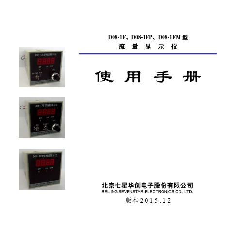
D08-1F 、D08-1FP 、D08-1FM 型流 量 显 示 仪使 用 手 册版本2 0 1 5 . 1 2使用须知尊敬的用户,感谢您购买本公司生产的D08系列流量显示仪。
本手册详细叙述了正确、安全使用该系列产品的必要事项。
产品使用者,请务必认真参阅本手册并理解后使用,在使用过程中,请注意带有标志的文字及注意事项中包含的所有内容。
对于未按照使用手册使用造成的财产损失或人身伤害,本公司有权不承担责任。
本手册对您安装、维护及故障维修时,必不可少,请妥善留存保管。
目录1. 用途和特点 (1)2. 主要技术指标 (2)3. 外观和操作面板 (2)4. 结构说明 (3)4.1 ±15V电源 (3)4.2 基准源和流量设定 (4)4.3 数字显示器 (4)4.4 阀控开关 (4)4.5 调零电位器 (4)4.6 1FP型的设定显示功能 (4)5. 安装和接线 (4)5.1 外形和开孔尺寸 (5)5.2 安装 (5)5.3 1F、1FP型接线 (6)5.4 1FM型接线 (8)5.5 保护板的安装 (8)5.6 MFC/MFM信号接线图 (9)6. 操作方法 (9)7. 参数设置 (10)7.1 流量单位指示的改变 (10)7.2 小数点位置改变 (11)7.3 显示量程的改变 (11)8. 注意事项 (12)9. 选型与订货规格填写 (13)D08 SERIES FLOW READOUT BOXESD08-1F、D08-1FP、D08-1FM型流量显示仪1. 用途和特点流量显示仪用于为气体质量流量控制器(MFC)和质量流量计(MFM)提供工作电源、操作控制、流量设定和流量数字显示等。
D08系列流量显示仪可直接与我公司生产的D07系列MFC(或MFM)配套使用。
同时原则上也可以与世界上其它型号的MFC(或MFM)配合使用。
D08-1F、1FM、1FP型流量显示仪采用小型塑料机壳,体积较小,便于安装。
D08-1D 型 流量显示仪
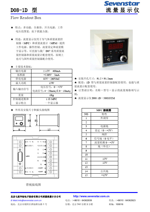
★ 外形及安装尺寸和插头接线图
96 91
9
15
信号地 电流输入
MFC
电流输出 信号地
信号地 电流设定 设定 内设 流量检测 阀控
地 ~220V ~220V
MFC 接线图
NO
特性
1
外调零
2
3
电源地
4
设定(0~+5V)
5
阀控
6
信号地(0 电平)
7
流量检测 0~+5V
8
地(外壳)
9
10
11
-15V
12
-15V
13
14
公共地
15
+15V
背视接线图
北京七星华创电子股份有限公司质量流量计分公司 E-Mail:mfc@ 地址:北京市朝阳区酒仙桥东路 1 号
电话:(+8610)64362939
传真:(+8610)64362923
D08-1D 型
Flow Readout Box
流量显示仪
★ 特点:多功能,全兼容,开关电源,工作 电压范围宽,抗干扰能力强。
★ 用途:流量显示仪用于为气体质量流量控 制器(MFC)和质量流量计(MFM)提供 工作电源、操作控制、流量设定和流量数 字显示等。可直接与我厂 D07 系列质量流 量控制器和质量流量计配套使用,原则上 也可与国外质量控制器配合使用。
★ 主要技术指标:
输出电源
±15V 400mA
基准源
+5.00V 5mA
供电电源
85V~260VAC
最大功耗15W源自输入输出信号电压信号:0~+5V
电流信号:4~20mA(或 0~10mA)
流量计说明书.pdf_1718715200.0919275

TABLE OF CONTENTS Introduction (4)Specifications (6)Installation (7)Operational Start-Up (9)Troubleshooting (11)Flow Monitor Information (12)Repair Kit Information (13)Statement of Warranty (15)INTRODUCTIONFluid entering the meter passes through the inlet flow straightener which reduces its turbulent flow pattern and improves the fluid’s velocity profile. Fluid then passes through the turbine blades causing it to rotate at a speed proportional to the fluid velocity. As each blade passes through the magnetic field, created at the base of the pickoff transducer, AC voltage (pulse) is generated in the pick-up coil (see Figure 1). These impulses produce an output frequency proportional to the volumetric flow through the meter. The output frequency is used to represent flow rate and/or totalization of fluid passing through the turbine flow meter.FIGURE 1Schematic illustration of electric signalgenerated by rotor movementTURBINE METERThe FTB-1400 Series Turbine Flow Meter is designed to withstand the rigorous demands of the most remote flow measurement applications. The FTB-1400 Series Flow Meter maintains measurement accuracy and mechanical integrity in the corrosive and abrasive fluids commonly found in oil field waterflood project pipelines, in-situ mining operations, offshore facilities and plant locations. Simple to install and service, it can operate in any orientation (horizontal to vertical) as long as the“flow direction” arrow is aligned in the same direction as the actual line flow. For optimum performance, the flow meter should be installed with a minimum of 10 diameters upstream pipe length and 5 diameters downstream pipe length.FIGURE 2Typical cross-section of FTB-1411 throughFTB-1441 turbine flow meterSPECIFICATIONSMATERIALS of CONSTRUCTION: Body : 316 Stainless SteelRotor : CD4MCU Stainless SteelRotor Support and Bearings : 316 Stainless SteelRotor Shaft : Tungsten CarbideOPERATING LIMITATIONS:Temperature: -150 °F to +350 °F (-101 °C to +177 °C) The metershould not be subjected to temperatures above +350° F(177° C), or below -150° F (-101° C) or the freezingpoint of the metered liquid. High temperatures willdamage the magnetic pick-up, while lower temperatureswill limit the rotation of the rotor.Pressure : Maximum pressure ratings as follows:5,000 psi ─ all NPT meters up to 2"2,000 psi ─ 3" male NPT1,500 psi ─ 4" male NPT1,000 psi ─ 6" male NPT800 psi ─ all grooved end metersNote: Consult factory for pressure ratings for flanged meters. Accuracy:± 1.0% of reading Repeatability: ± 0.1%Calibration: Water (NIST Traceable Calibration) Corrosion: All FTB-1400 series turbine meters are constructed ofstainless steel and tungsten carbide. The operator mustensure that the operating fluid is compatible with thesematerials. Incompatible fluids can cause deterioration ofinternal components and cause a reduction in meteraccuracy.Pulsation andVibration: Severe pulsation and mechanical vibration will affectaccuracy and shorten the life of the meterFiltration: If small particles are present in the fluid, it is recommendedthat a strainer be installed upstream of the meter (see Table 1 WARNING: Pressure in excess of allowable rating may cause the housing to burst and cause serious personal injury.FLOW MONITOR:For a complete flow monitor package, Omega offers the FTB-1400 Series Flow Monitors (see Appendix B on page 12 for flow monitor information). These digital signal processing displays utilize the low-level frequency input from the FTB-1400 Series Turbine Meters to calculate flow rate and total. When ordered with an Omega FTB-1400 Series Turbine Meter, the included factory calibration will provide dependable and accurate flow information.REPAIR KIT:The FTB-1400 Series Turbine Meter Repair Kit is designed for easy field service of a damaged flow meter, rather than replacing the entire flow meter (see Appendix B on page 12 for repair kit information).Repair parts are constructed of stainless steel alloy and tungsten carbide and are factory calibrated to ensure accuracy throughout the entire flow range. Each kit is complete and includes the calibrated K-factor which is used to recalibrate the flow monitor or other electronics to provide accurate output data.INSTALLATION INSTRUCTIONSPrior to installation, the flow meter should be checked internally for foreign material and to ensure the turbine rotor spins freely. Fluid lines should also be checked and cleared of all debris.The flow meter must be installed with the flow arrow, etched on the exterior of the meter body, pointing in the direction of fluid flow. Though the meter is designed to function in any position it is recommended, where possible, to install horizontally with the magnetic pick-up facing upward.The liquid being measured should be free of any large particles that may obstruct rotation of the rotor. If particles are present, a mesh strainer should be installed upstream before operation of the flow meter. (See Table 1 on page 8.)TABLE 1 Strainer Mesh Installation DetailsThe preferred plumbing setup is one containing a by-pass line (Figure 3 on page 10) that allows meter inspection and repair without interrupting flow. If a by-pass line is not utilized, it is important that all control valves be located downstream of the flow meter (Figure 4 on page 10).This is true with any restriction in the flow line that may cause the liquid to flash. If necessary, air eliminators should be installed to ensure that the meter is not incorrectly measuring entrained air or gas.PARTNUMBER STRAINER MESH CLEARANCE FILTER SIZE FTB-1411, FTB-142160 × 60 .0092 260 Micron FTB-1412, FTB-142260 × 60 .0092 260 Micron FTB-1413, FTB-142360 × 60 .0092 260 Micron FTB-142460 × 60 .0092 260 Micron FTB-1425 60 × 60 .0092 260 MicronFTB-1431 20 × 20 .0340 .86mm FTB-1441 20 × 20 .0340 .86mmCAUTION: Damage can be caused by striking an empty meter with a high velocity flow stream.It is recommended that a minimum length, equal to ten (10) pipe diameters of straight pipe, be installed on the upstream side and five (5) diameters on the downstream side of the flow meter. Otherwise, meter accuracy may be affected. Piping should be the same size as the meter bore or threaded port size.Do not locate the flow meter or connection cable close to electric motors, transformers, sparking devices, high voltage lines, or place connecting cable in conduit with wires furnishing power for such devices. These devices can induce false signals in the flow meter coil or cable, causing the meter to read inaccurately.If problems arise with the flow meter and monitor, consult Appendix A (Troubleshooting Guide) on page 11. If further problems arise, consult the factory.If the internal components of the turbine flow meter are damaged beyond repair, turbine meter repair kits are available. Information pertaining to the turbine meter repair kits is referenced in Appendix B on page 12.OPERATIONAL START-UPThe following steps should be followed when installing and starting the meter.WARNING: Make sure that fluid flow has been shut off and pressure in the line released before attempting to install the meter in an existing system.1. After meter installation, close the isolation valves and open theby-pass valve. Flow liquid through the by-pass valve for sufficient time to eliminate any air or gas in the flow line.CAUTION: High velocity air or gas may damage the internal components of the meter.2. Open upstream isolating valve slowly to eliminate hydraulic shockwhile charging the meter with the liquid. Open the valve to full3. Open downstream isolating valve to permit meter to operate.4. Close the by-pass valve to a full closed position.5. Adjust the downstream valve to provide the required flow ratethrough the meter. Note: The downstream valve may be used as a control valve.FIGURE 3Meter installation utilizing a by-pass line(Shown with an FTB-1400 Series Flow Monitor)FIGURE 4Meter installation without utilizing a by-pass lineAPPENDIX ATROUBLESHOOTING GUIDE Trouble Possible Cause RemedyMeter indicates higher than actual flow rate -Cavitation-Debris on rotor support-Build up of foreign materialon meter bore-Gas in liquid-Increase back pressure-Clean meter-Clean meter-Install gas eliminatorahead of meterMeter indicates lower than actual flow rate -Debris on rotor-Worn bearing-Viscosity higher than calibrated-Clean meter and add filter-Clean meter and add filter-Recalibrate monitorErratic system indication, meter alone works well (remote monitor application only) Ground loop in shielding Ground shield one placeonly. Look for internalelectronic instrumentground. Reroute cablesaway from electrical noiseIndicator shows flow when shut off Mechanical vibration causesrotor to oscillate without turningIsolate meterNo flow indication. Full or partial open position Fluid shock, full flow into drymeter or impact caused bearingseparation or broken rotor shaftRebuild meter with repairkit and recalibrate monitor.Move to location wheremeter is full on start-up oradd downstream flowcontrol valveErratic indication at low flow, good indication at high flow Rotor has foreign materialwrapped around itClean meter and add filterNo flow indication Faulty pick-up Replace pick-upSystem works perfect, except indicates lower flow over entire range By-pass flow, leak Repair or replace by-passvalves, or faulty solenoidvalvesMeter indicating highflow, upstream pipingat meter smaller thanmeter boreFluid jet impingement on rotor Change pipingOpposite effects of above Viscosity lower than calibrated Change temperature,change fluid or recalibratemeter11APPENDIX BFTB-1400 SERIES FLOW MONITOR Simplified Version• Displays rate and/or total• Large 8 digit by 3/4” display• Front panel programming• NEMA 4X enclosure• Five selectable units of measure• Programs in seven simple stepsPart Number InformationFTB 1400 X DMounting StyleM = Meter MountR =Remote MountS =Swivel Mount Advanced Version• Displays rate and/or total• Large 8 digit by 3/4” display• Front panel programming• NEMA 4X enclosure• Thirteen selectable units of measure• Selection of time intervals for rate measurement• Ten point linearization• Provides additional programming optionsPart Number InformationFTB 1400 X D AMounting StyleM = Meter MountR =Remote MountS =Swivel Mount1213FTB-1400 REPAIR KITFigure 5Typical turbine meter component directoryFlow Meter SizeRepair Kit FitsMeter Part NumberRepair KitPart Number3/8" FTB-1411,FTB-1421 FTB-1400A-RK 1/2" FTB-1412, FTB-1422 FTB-1400B-RK 3/4" FTB-1413, FTB-1423 FTB-1400C-RK 7/8" FTB-1424 FTB-1400D-RK 1" FTB-1425 FTB-1400E-RK 1-1/2" FTB-1431 FTB-1400F-RK 2" LowFTB-1441 FTB-1400F-RK Standard Magnetic Pick-upAll Meter SizesFTB-1400-MPNOTES 141516。
七星电子流量计 CS200产品使用手册(A,C,D)(+profibus+0-20ma)(su)

(0~1,2,3,5,10,20,30,50)
SLM
(0~2,3,5,10,20,30,50,100,200,300,500) SCCM
(0~1,2,3,5,10,20,30)
SLM
±1.0% S.P. (≥35% F.S.)
±0.35% F.S.(<35% F.S.)
±0.5% F.S.
±0.2% F.S.
对于未按照使用手册使用造成的财产损失或人身伤害,本公司有权不承担责任。 本手册在您安装、维护及故障维修时必不可少,请妥善留存保管。
1.3 安全注意事项
下列注意事项请结合使用手册查看。未按照注意事项进行操作所产生的一切后果本公司 不予承担。
a)请勿替换产品零部件或者改动产品
不要替换产品的任何零部件或者对仪器进行任何未授权的改动。在返厂进行重新标定或 维修的时候必须保证安全标签完好无损。
b)请联络专业工作人员为您服务 使用时勿擅自更换零部件,任何技术支持都必须由本公司授权的专业技术人员来为您服 务。
c)使用危险气体时请特别注意 如果使用危险气体,请做好预防措施,条件允许请完全吹洗仪器。如果危险气体潮湿, 须确保潮湿的危险气体不会和仪器以及密封材料产生化学反应。 d)吹洗仪器时特别注意 在从气路上拆卸仪器之前和安装仪器后都要对整个系统进行吹洗,用干燥气体吹洗通道 内剩余气体的残渣。 e)请遵照合适的步骤吹洗 产品必须在通风保护罩下进行吹洗,并且操作人员必须带上手套进行保护。 f)请勿在爆炸性环境下使用本产品 为了避免产生爆炸,不要在爆炸性环境下使用本产品,除非本产品获得有效认证 。 g)请使用合适的接头并按照相关的紧固规程来操作 所有仪器的接头都必须和产品说明书上的型号相符,且与仪器所使用的接头相一致且与 仪器所使用的接头相配套。拧紧接头的时候请按照产品操作指导说明书来操作。 h)请检查产品接头处是否漏气 请仔细的检查所有的零部件接口以确保在安装过后没有漏气。
七星华创SC29 D08-8C-8CM
9 关于产品的上位机软件说明
11
9 关于产品的上位机软件说明
28
附录一:D08-8C 积算仪通信协议
12 附录二:D08-8CM 积算仪通信协议
29
D08 SERIES FLOW READOUT BOXES
D08-8C 型数字流量积算仪
技术说明书
1.用途
D08-8C 型数字流量积算仪为气体质量流量控制器(MFC)提供工作电源、操作控制、数字 显示瞬时流量和累积流量。D08-8C 型数字流量积算仪可直接与我厂 D07 系列质量流量控制器配 套使用。同时原则上可以与世界上其它型号的质量流量控制器配合使用。
D08-8C、D08-8CM 型
流量积算仪
D08-8C、D08-8CM 型流量积算仪版本:
作者
日期
描述
赵迪 赵迪 赵迪
2005.05.12 2006.03.06 2010.03.15
初始版本 增加了 RS485 半双工多机通讯功能 下位机程序改进,产品可靠性提高; 对于 D08-8C 产品,通讯协议中增加“读瞬时 流量设定值”指令,具体见本手册附录一。
连续增加。 d)“减少”键:为满量程、流量设定和地址设置的减少键,每按一次其数值减少 1,连按则数值
2 主要技术指标................................ 19
3 工作原理........................................ 2
3 工作原理........................................ 20
4 安装和接线.................................... 2
5.3 按键定义......................................... 23
- 1、下载文档前请自行甄别文档内容的完整性,平台不提供额外的编辑、内容补充、找答案等附加服务。
- 2、"仅部分预览"的文档,不可在线预览部分如存在完整性等问题,可反馈申请退款(可完整预览的文档不适用该条件!)。
- 3、如文档侵犯您的权益,请联系客服反馈,我们会尽快为您处理(人工客服工作时间:9:00-18:30)。
D08-1F 、D08-1FP 、D08-1FM 型流 量 显 示 仪使用 手 册版本2 0 1 0 . 0 4使用须知尊敬的用户,感谢您购买本公司生产的D08系列流量显示仪。
本手册详细叙述了正确、安全使用该系列产品的必要事项。
产品使用者,请务必认真参阅本手册并理解后使用,在使用过程中,请注意带有标志的文字及注意事项中包含的所有内容。
对于未按照使用手册使用造成的财产损失或人身伤害,本公司有权不承担责任。
本手册对您安装、维护及故障维修时,必不可少,请妥善留存保管。
目录1. 用途和特点 (1)2. 主要技术指标 (2)3. 外观和操作面板 (2)4. 结构说明 (3)4.1 ±15V电源 (3)4.2 基准源和流量设定 (4)4.3 数字显示器 (4)4.4 阀控开关 (4)4.5 调零电位器 (4)4.6 1FP型的设定显示功能 (4)5. 安装和接线 (4)5.1 外形和开孔尺寸 (5)5.2 安装 (5)5.3 1F、1FP型接线 (6)5.4 1FM型接线 (8)5.5 保护板的安装 (8)5.6 MFC/MFM信号接线图 (9)6. 操作方法 (9)7. 参数设置 (10)7.1 流量单位指示的改变 (10)7.2 小数点位置改变 (11)7.3 显示量程的改变 (11)8. 注意事项 (12)9. 选型与订货规格填写 (13)D08 SERIES FLOW READOUT BOXES第 1 页 共 13 页D08-1F 、D08-1FP 、D08-1FM 型流 量 显 示 仪1. 用途和特点流量显示仪用于为气体质量流量控制器(MFC )和质量流量计(MFM )提供工作电源、操作控制、流量设定和流量数字显示等。
D08系列流量显示仪可直接与我公司生产的D07系列MFC (或MFM )配套使用。
同时原则上也可以与世界上其它型号的MFC (或MFM )配合使用。
D08-1F 、1FM 、1FP 型流量显示仪采用小型塑料机壳,体积较小,便于安装。
流量输入输出信号,除了具有标准的0~+5V 电压信号外,还有4~20mA 或0~10mA 的电流信号。
D08-1F 型流量显示仪带有流量设定和阀控功能,可与工作电源为±15V 的MFC (或MFM )配套使用。
D08-1FP 型流量显示仪则在D08-1F 型流量显示仪的基础上增加了设定显示功能。
D08-1FM 型无流量设定和阀控功能,专为工作电源为±15V 的MFM 配套使用。
图1. 流量显示仪与质量流量控制器配套使用第 2 页 共 13 页2. 主要技术指标3. 外观和操作面板三种型号的流量显示仪均采用标准嵌装式塑料机箱,外观和操作面板见图2~4。
图2. 1F 型流量显示仪外观调零电位器阀控开关流量单位指示流量显示窗设定电位器第 3 页 共 13 页图3. 1FP 型流量显示仪外观图4. 1FM 型流量显示仪外观4. 结构说明4.1 ±15V 电源1F 、1FP 、1FM 型显示仪的电源采用开关电源,具有工作电源电压范围宽和抗干扰能力强的特点。
集成稳压模块内部有过热、过流保护,且具有性能稳定、可靠性高等特点。
显示选择开关4.2 基准源和流量设定在1F和1FP型流量显示仪中设计有+5.00V基准电源,它加载到设定电位器上,通过操作者手动调节面板上的设定电位器,提供0~5.00V的设定电压输出,用来控制MFC的流量。
该电源设计有开机软启动电路,当显示仪接通电源时,基准源缓慢从0V升至+5.00V,软启动时间约为20秒。
4.3 数字显示器显示器用来显示流量,采用三位半数字面板表直读,最大显示数为1999。
流量显示的单位有“SCCM”、“SLM”、“%”三种。
通常,流量显示仪与MFC(或MFM)配套出厂时,将显示器显示的量值和单位与其对应的MFC(或MFM)通道的量值和单位调整成一致。
若用户订货时没有注明MFC(或MFM)的流量规格,则出厂调整为按满量程的百分比显示,它与任何规格的MFC(或MFM)配合使用时,满量程均显示“100.0%”。
在流量显示仪的面板上,设计有流量单位指示灯,当代表各自单位的发光二极管亮时表示流量是SCCM或SLM,若两个均不亮,表示单位为%。
各通道显示的数值、小数点和流量单位均可通过改变和适当调整而满足使用的不同要求。
4.4 阀控开关1F和1FP型流量显示仪的面板上装有“阀控”开关。
阀控开关有三个位置,正常工作时置于“阀控”位,需要通气吹洗管路时,置于“清洗”位,不用时应置于“关闭”位。
4.5 调零电位器面板上设计有外“调零”电位器,可以用来在小范围内调整D07系列MFC(或MFM)产品的零点。
4.6 1FP型的设定显示功能1FP型流量显示仪比1F型流量显示仪增加了设定显示功能。
将面板的显示选择开关拨至“设定显示”,数字显示器显示MFC的设定流量;将显示选择开关拨至“流量显示”,则显示MFC的实际流量。
5. 安装和接线第 4 页共13 页第 5 页 共 13 页图6. 1F 、1FP 、1FM 型流量显示仪附件将长支架插入显示仪外壳上下两侧的长方形沟槽内,两端弯曲处朝上,如图图7. 插入长支架第 6 页 共 13 页5.2.3将鞍形支架插入长方形沟槽后部的孔中,如图8所示。
图8. 插入鞍形短支架5.2.4将螺钉穿过长支架后弯板的圆孔,旋入鞍形支架的螺纹孔。
拧紧螺钉,使长支架的前弯板和显示仪外壳前端的后檐紧紧夹住面板,达到固定显示仪的目的。
如图9所示。
A.穿入螺钉B.旋紧螺钉C.夹紧面板图9. 将显示仪固定在面板上5.3 1F 、1FP 型接线1F 和1FP 型流量显示仪的电源线和外控信号端子,见图10。
1F 型和1FP 型流量显示仪,除了能提供0~+5V 的电压输入输出信号之外,还具有电流输入输出功能。
可以通过后部接线端子的跳线,改变输入功能。
通常出厂时,显示仪接线为“内设”方式,见图10a ,将“设定”与“内设”线短连,通过面板上的设定电位器调节流量。
当接线端子上的“设定”与“内设”的连线断开,则仪表处于“电压设定”的“外设”状态,由用户自己提供的(计算机数模转换器)0~+5.00V电压接入“设定”和“信号地”两端,作为外部设定信号来调节流量。
参见图10b,也可以外接一个设定转换开关,进行内外设定的转换。
当接线端子上的“设定”与“电流设定”短连,参见图10c,则仪表处于“电流设定”状态,由“电流输入”端子输入的4~20mA(或0~10mA)信号调节流量。
无论仪表在电流设定还是电压设定状态,能同时输出电压和电流信号。
“流量检测”端子相对“信号地”输出0~+5V流量信号;“电流输出”端子输出4~20mA(或0~10mA)的流量信号。
输入输出电流的形式,是4~20mA还是0~10mA,可根据用户订货的要求,在出厂时调定,并在机壳后铭牌上的电流信号复选框上勾选。
a. “内设”接线图b. 内外“电压设定”转换接线图图10. D08-1F/1FP型背视接线图第7 页共13 页第 8 页 共 13 页5.4 1FM 型接线D08-1FM 型流量显示仪的电源线和输出信号接线端子,见图11。
5.5 保护板的安装:接线完毕,将附件中的保护板用自攻螺钉固定到后面板上方。
如图12所示。
图12. 保护板安装示意图第 9 页 共 13 页5.6 MFC/MFM 信号接线图图13. MFC/MFM 信号插座和接线6. 操作方法流量显示仪与MFC (或MFM )连接后的详细操作说明,可参见D07系列MFC (或MFM )的有关技术说明书。
6.1 开机:接通电源,则仪表开始工作(1F 、1FP 、1FM 型无电源开关,将外部电源接通即可)。
1 8 9 15第 10 页 共 13 页6.2 MFC (或MFM )调零:开机预热15分钟以后,在不通气的情况下,可以使用小改锥调整显示仪面板上的“调零”电位器,对MFC (或MFM )调零。
6.3 阀控开关有三个位置,正常工作时置于“阀控”位(1FM 型无此操作)。
6.4 流量内设定信号由面板上的十圈电位器调节(1FM 型无此操作)。
6.5 关机:切断外接电源即可关机。
7. 参数设置输出电流信号、流量单位指示和量程要根据用户要求和所配的MFC (MFM )来设置,通常由厂家在出厂前配好。
若用户在使用中要自己改变量程和单位,可以打开流量显示仪外罩,对转换板上的有关拨动开关和电位器进行调整,拨动开关和电位器位置参见图14。
图14. 拨动开关和调整电位器位置图7.1 流量单位指示的改变“SCCM 、SLM 、%”流量单位改变的拨动开关位置见图15。
图15. 流量单位指示改变的拨动开关位置图RP3S3-1,3-2 S4-1,4-2,4-3,4-4S3-1 S3-2 SCCM: S3-1—on S3-2—offS3-1 S3-2 % : S3-1—off S3-2—off S3-1 S3-2SLM: S3-1—off S3-2—on第 11 页 共 13 页7.2 小数点位置改变流量显示小数点位置可以通过拨动开关S4来改变,见图16。
图16. 小数点改变对应的拨动开关位置图7.3 显示量程的改变显示器显示量程的改变包括显示的有效数据和小数点的改变,小数点位置的改变方法见7.3条,显示有效数值的改变按以下步骤进行。
a. 切断电源,取下MFC/MFM 插头和电源线,(取下“设定”与“内设”的短连线)打开外壳。
b. 如果是改变1FM 型流量显示仪的量程,可从后面板接线端子上的“流量检测”和“信号地”两端输入+5.00V 电压;如果是改变1F 型或1FP 型流量显示仪的量程,可将后面板接线端子上的“流量检测”和“内设”端子用导线短路,并将前面板上的设定电位器顺时针旋转到最大值(使内设输出电压为满量程值+5.00V )。
c. 接通显示仪电源,20秒钟后,观察前面板上数字显示器的显示值,用小一字螺丝刀调节电位器RP3(见图10)使显示器显示的数值与对应的 MFC/MFM 通道的满量程值一致(注意对应3-1/2位数字电压表,显示的数据范围是0~1999,同时注意小数点的位置要匹配)。
d. 切断电源,对于1FM 型流量显示仪,要断开外接+5.00V 电压;对于1F 型和1FP 型流量显示仪,要断开“流量检测”和“内设”的短连导线。
e. 量程调整结束,装上外壳,恢复“设定”与“内设”的短连线,就可以正常使用了。
DP1 流量显示器 DP2 DP3第 12 页 共 13 页8. 注意事项8.1 禁止项仪表盒内部的电位器在出厂前均已调整好,用户不得随意自行调整。
15V 电源的功率有限,用户不能超负荷使用。
8.2 改量程注意非专业维修人员和电器技术人员,不能进行显示量程的改变和调整。