SMC流量计pf3说明书
流量计说明书
)5$1&( ZZZRPHJDIU
*(50$1< ZZZRPHJDGH 'HFNHQSIURQQ *HUPDQ\
%(1(/8; ZZZRPHJDQO
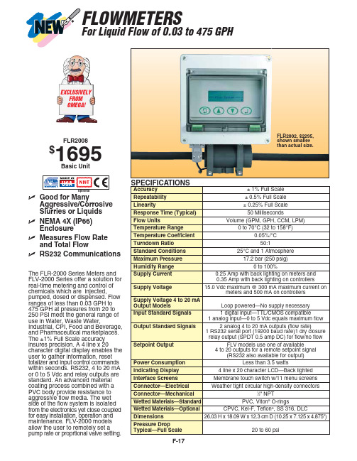
Indicating Display
4 line x 20 character LCD—Back lighted
Interface Screens
Membrane touch switch w/11 menu screens
Connector—Electrical
Weather tight circular high-density connectors
FLR2002
$2295 FLV2002
FLR2003
1995 FLV2003
FLR2004
1995 FLV2004
FLR2005
1995 FLV2005
FLR2006
1995 FLV2006
FLR2007
1995 FLV2007
FLR2008
1695 FLV2008
FLR2009
1795 FLV2009
Connector—Mechanical
1⁄2" NPT
Wetted Materials—Standard
PVC, Viton® O-rings
Wetted Materials—Optional
CPVC, Kel-F, Teflon®, SS 316, DLC
Dimensions
26.03 H x 18.09 W x 12.3 cm D (10.25 x 7.125 x 4.875")
15.80 31.70 79.20 158.50 317.00 475.50
SMC数字流量开关操作手册说明书
Digital Flow Switch (Display Part) Operation Manual For AirPF2A300/301 SeriesPF2A310/311 SeriesFor Pure Water/Chemical Fluid PF2D300/301 SeriesFor WaterPF2W300/301 SeriesPF2W330/331 SeriesURL SAFETY2Model Indication Method4Name and Functions of Individual Parts 6Installation7Outline with Dimensions8Example of Internal Circuit and Wiring 9Setting 10Initialize11Display Function of Integrated Flow Rate Value 15Instantaneous Flow Rate Setting Mode16Integrated Flow Rate Setting Mode 19Output Selection 20Other Functions 23Specification24CONTENTSThank you for purchasing the SMC PF2*3**Series Digital Flow Switch.Please read this manual carefully before operating digital flow switch and understand digital flow switch, its capabilities and limitations.Please keep this manual handy for future reference.OPERATOR•This operation manual has been written for those who have knowledge of machinery and apparatus that use pneumatic equipment and have full knowledge of assembly, operation and maintenance of such equipment.•Please read this operation manual carefully and understand it before assembling, operating or providing maintenance service to the flow switch.32NOTEFollow the instructions given below when handling your flow switch.Otherwise, the switch may be damaged or may fail, thereby resulting in malfunction.•Do not drop it, bring it into collision with other objects or apply excessive shock (490m/s 2or more).•Wiring correctly.•Do not wiring while power is on.•Although the flow switch complies with the CE Marking, since it does not have the thunder serge protection, please carry out protection to thunder serge by the equipment side.•Although the flow switch complies with the CE Marking, since the equipment and apparatus which are made to generate the serge (Electro-magnetic lifter, High frequency induction furnace, Motor etc.) around the flow switch should perform measure against serge come out.•Do not use with power cable or high-voltage cable in the same wire route.•Do not use in a place in which water, oil, or a chemical splashes.•Do not push the setting buttons by a sharply pointed object.•Turn on the power supply of a flow switch for Air, when flow is zero.Some initial drift occurs during ten minutes after turning the power on.•Start measurement by the flow switch three seconds after turning on the power. (Also in momentary interception of the power supply by reset etc.) Please take a measure by the program of equipment etc.•Maintain the switch status for measurement output before setting when initializing or setting a flow rate of the flow switch.Measure after checking impacts to the equipment.Carry out a setup since a control system is shut down if required.The Digital Flow Switch and this manual contain essentialinformation for the protection of users and others from possible injury and property damage and to ensure correct handling.Please check that you fully understand the definition of the following messages (signs)before going on to read the text, and always follow the instructions.Please read the operation manuals of related apparatus and understand it before operating the flow switch.Do not disassemble, remodel (including change of printed circuit board) or repair.An injury or failure can result.Do not operate beyond specification range.Fire, malfunction or switch damage can result.Please use it after confirming the specification.Do not operate in atmosphere of an inflammable, an explosive and corrosive gas.Fire or an explosion can result.This flow switch is not an explosion-proof type.54NOTE 1:The new Measurement Low prohibits use in Japan of flowswitches with a unit selection function.NOTE 2:Fixed unit for instantaneous flow rate is :L/minfor integrated flow rate is :LSeparate Type Display PartA : AirD : Pure Water/Chemical Fluid W : Water•About sensor partThe type of the sensor part combined with a display part is indicated to be PF *5**with this manual.Refer to the following correspondence table for the sensor part type combined with each display part.BodyOutput (OUT1) Lamp (Green):Lit when OUT1 is ON. Flickers when an overcurrent erroroccurs.Output (OUT2) Lamp (Red):Lit when OUT2 is ON. Flickers when an overcurrent erroroccurs.LED Display:Displays a flow rate, set mode status, selected display unitand error code.Button (UP): Selects a mode and increases a set ON/OFF value.Button (DOWN): Selects a mode and decreases a set ON/OFFvalue.Button (SET): Changes the mode and sets a set value. RESETPressing the and buttons simultaneously will activate the RESET function.Use this function to clear errors when a trouble occurs.Panel Mount Adapter type ZS-22-EPanel Mount Adapter APanel Mount Adapter BBracket are includedMounting•Install the Display Part on the panel, once the Panel Mount Adaptor Bremoves.•Insert Panel Mount Adapter B supplied as an accessory intoSection A of Panel Mount Adapter A.Push Panel Mount Adapter B from behind till the display is fixedonto the panel.The pin of Panel Mount Adapter B engages the notched part ofPanel Adapter A to fix the display.•The switch can be mounted on a panel with a thickness of 1.0 to3.2mm.•See the illustration below for panel cut dimensions.Panel Cut Dimensions Accessories LED DisplayLamp (Red)SETButton (UP)7 698++0.5Panel Thickness: 1 to 3.2mmPanel Cut DimensionsOutput SpecificationBe sure to select a sensor in SMC PF *5**series for accurate measurement of flow rates.The display outputs only switch output.Analog output is output directly by the sensor part. See theoperation manual of the sensor part for the complete information. Connection•Turn the power off before making connection.•Install the cable separately from the route for power cable or high-voltage cable. Otherwise, malfunction may potentially result due to noise.•Use compression terminals for connection to the terminal board.See the full view of dimensions diagram for details of the terminal board.–0NPN Open Collector Output 2OutputsMax. 30V, 80mAInternal Voltage Drop 1V or less–1PNP Open Collector Output 2Outputs Max 80mAInternal Voltage Drop 1.5V or lessPF ∗5 SeriesPF ∗5 SeriesSetting ProceduresKeep pressing the button longer than two seconds. Remove the finger off the button when one of the characters of LED display column of the following table is displayed.1. Flow Rate Range SettingPress the button and select the flow rate range.Press thebutton to set.2. Display Mode SettingSelect whether to display instantaneous flow rate orintegrated flow rate.To change the Display mode, press thedesired flow rate to display. Then press the button.[d_1] and [d_2] respectively indicate the instantaneous flow rate and integrating flow rate.11103. Selecting Display Unit(In case [-M] is not assigned to unit specification in model indication) Refer to page 14.4. Output Method SettingThree output methods are available, namely, instantaneous switch, integrating switch and integrating pulse. The method for output to OUT1 or OUT2 is set as follows.1)First, the output method for OUT1 is set.*Press the button and select the instantaneous switch,integrating switch or integrating pulse.*Press the button to set.[o10] [o11] and [o12] respectively indicate the2)Select one output method for OUT2 from three output methods by pressing the button, as in OUT1.*Press the button to set.[o20] [o21] and [o22] respectively indicate theinstantaneous switch, integrating switch and integrating pulse.5. Output Mode SettingTwo output modes are available, namely, the Reverse Output modeand Non-Reverse Output mode. An output mode for OUT1 andOUT2 is set.1)First, the output method for OUT1 is set.*Press the button and select the Reverse Output mode or Non-Reverse Output mode.*Press the button to set.[1_n] and [1_P] respectively indicate the Reverse Outputmode and Non-Reverse Output mode.mode and Non-Reverse Output mode by pressing the button,as in OUT1.*Press the button to set.[2_n] and [2_P] respectively indicate the Reverse Outputmode and Non-Reverse Output mode.13 1215•Press the button first, then the button, to press both buttons simultaneously. Integration starts when [–] flickers.•Lower three digits of an integrated value are always displayed.Press the button when wishing to check upper three digits.•Pressing the button enables to display an instantaneous flow rate even during integration.•To stop integration, press the button first, then the button,to press both buttons simultaneously.The display will keep the present integrated value.To clear display of an integrated value, press both the and buttons simultaneously longer than two seconds.To further continue integration from the saved value, repress thebutton first, then the button, to press both buttons simultaneously.1716Manually set an actuation value of the instantaneous-value switch in case the instantaneous switch is selected in initialization.The output method is also set in accordance with the value set manually. Set the output method while referring to the output method described below.1.Keep pressing the button and remove the finger off when [F-1] is displayed.2.Repress the button to set for input of a set value in [n_1] (P_1 in the Non-Reverse Output mode) for OUT1.In case the Reverse Output mode is selected in initialization, [n_1]and the set value will be displayed alternately.(In case the Non-Reverse Output mode is selected in initialization,[P_1] and the set value will be displayed alternately.) 3.Press the or buttons to select a desired set value.Press the button to increase the set value or the button to decrease the set value.4.Press the button to set the set value and to move to the setting mode for [n_2] (P_2 in the Non-Reverse Output mode).In case the Reverse Output mode is selected in initialization, [n_2]and the set value will be displayed alternately.(In case the Non-Reverse Output mode is selected in initialization,[P_2] and the set value will be displayed alternately.) 5.Press the or buttons to select a desired set value.Press the button to increase the set value or the button todecrease the set value.6.Press the button to set the set value and to move to the setting mode for OUT2.Set the set value as in OUT1.In case the Reverse Output mode is selected for the OUT2 setting in initialization, [n_3] or [n_4] and the set value will be displayed alternately.In case the Non-Reverse Output mode is selected in initialization,[P_3] or [P_4] and the set value will be displayed pleting settings for [n_1] to [n_4] ([P_1] to [P_4] in the Non-Reverse Output mode) will finish flow rate setting and the mode will return to the Measurement mode.Manual1918The flow rate flowing through the flow switch will be set as areference value and a Hysteresis (H) will be set automatically at a value 3digits lower when setting auto preset input.The output method for setting by auto presetting is only hysteresis mode.1.Keep pressing the button and remove the finger off when [F_1] is displayed.2.Press the button and change [F_1] in the display to [F_2].3.Press the button and set the auto preset state of OUT1.The display will change to show [AP1] .(In case OUT1 setting is not needed, press the and button simultaneously.)4.Prepare the equipment to set the flow rate of OUT1 and flow fluid of the required flow rate.5.Pressing the button will automatically read the flow rate. A value 3digits lower will be set automatically as a Hysteresis (H).The display will show [A1L] and the set value alternately.6.Press the button and set auto preset state of OUT2.The display will change to show [AP2].(In case OUT2 setting is not needed, press the and buttons simultaneously.)7.Prepare the equipment to set the flow rate of OUT2 and flow fluid of the required flow rate.8.Pressing the button will automatically read the flow rate. A value 3digits lower will be set automatically as a Hysteresis (H).The display will show [A2L] and the set value alternately.9.Press the button to finish the Auto Presetting mode and themode will return to the Measurement mode.Auto Presetting•The switch is set to an integrated flow rate.•Integrated flow rate is displayed by switchingdividing into lower three digits and upper three digits. 1.Keep pressing the button and remove the finger off when [F_1] or [F_3] is displayed.Proceed to Step 3. if [F_3] is displayed.([F_1] will be displayed in case the instantaneous switch is selected for any switch output in initialization. In other cases,[F_3] will be displayed.)2.When [F_1] is displayed, push the button till the display shows [F_3]. The subsequent setting operation will be the same as that when [F_3] is displayed. Set as follows.3.Set as follows if [F_3] is displayed.1)Press the button and display the lower three digits of the integrated flow rate of OUT1.2)Press the or buttons and adjust the set value to the desired value.3)Press the button to set. The upper three digits of OUT1 will be displayed.4)Press the or buttons and adjust the set value to the desired value.5)Press the button to set. The lower three digits of OUT2 will be displayed.6)Press the or buttons and adjust the set value to the desired value.7)Press the button to set. The upper three digits of OUT2 will be displayed.8)Press the or buttons and adjust the set value to the desired value.9)Press the button to finish setting of an integrated flow rate and the mode will return to the Measurement mode.Instantaneous Switch Output MethodFour output methods can be selected by selecting an output modeOne of these four output methods can be selected for each output.•OUT1 and OUT2 can be set independently.•1digit flow rate conversion will be a minimum set unit. See thespecification for the set flow rate units.•When setting in the Auto Presetting mode, the Hysteresis mode willbe set automatically. Hysteresis in this case will be 3digits fixed.•In the Window Comparator mode, leave between [P_1] and [P_2]or between [n_1] and [n_2] values more than seven digits.•The following is given using OUT1 as an example. Thedescriptions for OUT2 are the same as those for OUT1, under theconditions that [n_1] and [n_2] should be replaced by [n_3] and[n_4] and [P_1] and [P_2] should be replaced by [P_3] and [P_4].20212322To reset display of Error 1, 2 or 4, press theandbuttons simultaneously.Integrating Switch Output•Two output methods can be selected by selecting an output mode.One of these two output methods can be selected for each output.•OUT1 and OUT2 can be set independently.•The following is given using OUT1 as an example. Thedescriptions for OUT2 are the same as those for OUT1, under the conditions that 1nL and 1nH should be replaced by 2nL and 2nH and 1PL and 1PH should be replaced by 2PL and 2PH.Integrating Pulse Output•Pulse output for integrated flow rate measurement.Key Lock FunctionThis function prevents errors such as changing a set value by mistake.Lock•Keep pressing the button longer than three seconds.The display will change to show [F_1] Æ[***] Æ[unL.]Remove the finger off the button when [unL] is displayed.([***]:Refer to the LED display column in the table, Page11)•Press the button to set the display to [Loc]•Press the button and return to the Measurement mode.Unlock •Press the button longer than three seconds. Remove the finger off the button when [Loc] is displayed.•Press the button to change the display to [unL]•Press the button and return to the Measurement mode.Error Display and TroubleshootingIn case an error occurs, take the following actions:2524*1:The flow rate indication range is corresponding to the flow rate range set up bythe initialization.*2:With a unit selection function(Without a unit selection function, fixed to SI units(L/min or L))*3:Two units in normal condition (0˚C/ 101.3kPa) or standard condition (20˚C/101.3kPa/ 65%RH) can be selected.*4:This is an overall accuracy combined with PF2A 5**.*5:Select whether to switch output or pulse output of integrated flow rate by theinitialization.*6:Window Comparator mode. Hysteresis (H) will be in 3digits.Separate [P_1] and [P_2], as well as [n_1] and [n_2], more than 7digits.(In case of the output 2, n_1,2 becomes n_3,4 and P_1,2 becomes P_3,4)*7:The display part conforms entirely to the CE standard.2627。
流量计仪表操作说明

目录仪表的键盘和前面板-------------------------------------2 仪表功能----------------------------------------------------4 仪表程序----------------------------------------------------4 仪表键盘和中控方式的转换----------------------------6 仪表的启动和停止----------------------------------------7 仪表重量和容积方式的转换----------------------------8 给定量的输入----------------------------------------------8 显示事件信息----------------------------------------------8 服务数据----------------------------------------------------9 标定功能----------------------------------------------------9 调零-----------------------------------------------------14 计数器1或2的复位-------------------------------------13 安装与调整-------------------------------------------------13 维护与保养-------------------------------------------------14 事件信息----------------------------------------------------16(一)仪表的键盘1各按键的作用如下:启动键和停止键。
SMC说明书

-2No.PS##-OMM0007-B
tion
The product is provided for use in manufacturing industries. The product herein described is basically provided for peaceful use in manufacturing industries. If considering using the product in other industries, consult SMC beforehand and exchange specifications or a contract if necessary. If anything is unclear, contact your nearest sales branch.
-1No.PS##-OMM0007-B
Safety Instructions
These safety instructions are intended to prevent hazardous situations and/or equipment damage. These instructions indicate the level of potential hazard with the labels of "Caution", "Warning" or "Danger". They are all important notes for safety and must be followed in addition to International standards (ISO/IEC) ∗1) and other safety regulations.
SMC PFG3# Series数字流量监测仪操作手册说明书

Simple Setting ModeFunction Selection ModeMaintenanceNote: Specifications are subject to change without prior notice and any obligation on the part of the manufacturer.© 2017 SMC Corporation All Rights Reserved Specifications/Outline with Dimensions (in mm)TroubleshootingAkihabara UDX 15F , 4-14-1, Sotokanda, Chiyoda-ku,Tokyo 101-0021, JAPAN Phone: +81 3-5207-8249Fax: +81 3-5298-5362URL Before UseDigital Flow MonitorPFG3# SeriesMounting and InstallationOutline of SettingsThank you for purchasing an SMC PFG3# Series Digital Flow monitor.Please read this manual carefully before operating the product and make sure you understand its capabilities and limitations. Please keep this manual handy for future reference.Safety InstructionsThese safety instructions are intended to prevent hazardous situations and/or equipment damage.These instructions indicate the level of potential hazard with the labels of"Caution", "Warning" or "Danger". They are all important notes for safety and must be followed in addition to International standards (ISO/IEC) and other safety regulations.OperatorSafety InstructionsInstallationMounting with bracketMount the bracket to the body with mounting screws (Self tapping screws:Nominal size 3 x 8L (2 pcs)), then set the body to the specified position.∗: Tighten the bracket mounting screws to a torque of 0.5±0.05 Nm.Self tapping screws are used, and should not be re-used several times.•Bracket A (Part No.: ZS-46-A1)•Bracket B (Part No.: ZS-46-A2)∗: The panel mount adapter can be rotated through 90 degrees for mounting.Mounting with panel mount adapterMount part (a) to the front of the body and fix it. Then insert the body with (a)into the panel until (a) comes into contact with the panel front surface. Next,mount part (b) to the body from the rear and insert it until (b) comes into contact with the panel for fixing.•Panel mount adapter WiringWiring connectionsConnections should be made with the power supply turned off.Use a separate route for the product wiring and any power or high voltage wiring. Otherwise, malfunction may result due to noise.If a commercially available switching power supply is used, be sure to ground the frame ground (FG) terminal. If the switching power supply is connected for use, switching noise will be superimposed and it will not be able to meet the product specifications. In that case, insert a noise filter such as a line noise filter/ferrite between the switching power supplies or change the switching power supply to the series power supply.∗: 3 step setting mode, simple setting mode and function selection mode settings are reflected each other.Core wire colour Black WhiteGreyBlueDC(+)OUT1OUT2Analogue output/External input/Copy function DC(-)Internal circuit and wiring examples•NPN open collector 2 output + Analogue output Max.30 V,80 mAResidual voltage: 1 V or lessMax. 80 mAResidual voltage: 1.5 V or lessRefer to the product catalogue or SMC website (URL ) for more information about other internal circuit and wiring examples.Set the flow range, display unit and NPN/PNP output specifications of the connected sensor.button between 3 and 5sec.[F 0] Setting of the switching function of the flow range, display unit and switchoutput specifications is completed.button 2 sec. or longer.Move on to the flow range setting.button.When the products with a units selectionbutton to move on to When fixed to SI unitWhen other than [USEr] is selected,button to move on to NPN/PNP specifications.button to set.Move on to the switching setting of switch output NPN/PNP specifications.button to set.Return to function selection mode.button to set.Measurement mode[3 step setting mode (hysteresis mode)]In the 3 step setting mode, the set value (P_1 or n_1, P_2 or n_2) and hysteresis (H_1, H2) can be changed.button once when the item to be changed is displayed on the sub button to change the set value. The set value can be buttons are pressed and held simultaneously for 1 second or longer, the set value is displayed as [- - -], and the setvalue will be the same as the current flow value button.button to complete the setting.from P2L to P2H) during window comparator mode. Set P1L/P2L, the lower limit of the switch operation, and P1H/P2H, the upper limit of the switch operation and WH1/WH2 (hysteresis) following the instructions given on above.(When reversed output is selected, the sub display (left) shows [n1L/n2L] and [n1H/n2H].)In accumulated output mode, the switch will start at the set accumulated flow rate.Set each P1/P2 (set value), referring to the Setting method on above.(When reversed output is selected, the sub display (left) shows [n1/n2].)∗: Set OUT2 in the same way.∗: Setting of the normal/reverse output switching and hysteresis/window comparator mode switching are performed with the function selection mode [F 1] Setting of OUT1 and [F 2] Setting of OUT2.flowvalue button between 1 and 3 seconds in measurementmode. [SEt] is displayed on the main display. When the button is released while in the [SEt] display, the current flow value is displayed on the main display, [P_1] or [n_1] is displayed on the sub display (left),and the set value is displayed on the sub display (right)(Flashing).button, and press the button to set the value. Then, the setting moves to hysteresis setting. (The snap shot function can be used.)button to set the be used.)button for 2 seconds or longer to complete the setting.The product will return to measurement mode.In the window comparator mode, set P1L/P2L, the lower limit of the switchoperation, and P1H/P2H, the upper limit of the switch operation and WH1/WH2(hysteresis) following the instructions given on above.(When reversed output is selected, the sub display (left) shows [n1L/n2L] and [n1H/n2H].)Default settingThe default setting is as follows. If no problem is caused by this setting,keep these settings.Function selection modebutton between 3 and 5seconds, to display [F 0]. Select to button for 2 seconds or longer in function selection mode to return to measurement mode.∗configuration of other functions, [- - -] is displayed on the sub display (right).Switching function of [F 0] Flow range,display unit and switch output specifications[F 2] Setting of OUT2Same setting as [F 1] OUT1.the units selection function.Snap shot functionbuttons for 1second or longer shows [- - -], and the values corresponding to the current flow values are automatically displayed.Peak/bottom value indicationThe maximum (minimum) flow when the power is supplied is detected and updated.button in measurement mode.Key-lock function Reset operationTo set each of these functions, refer to the SMC website(URL ) for more detailed information, or contact SMC.How to reset the product after a power cut or forcible de-energizingThe setting of the product will be retained as it was before a power cut or de-energizing. The output condition is also basically recovered to that before a power cut or de-energizing, but may change depending on the operating environment.Therefore, check the safety of the whole installation before operating the product. If the installation is using accurate control, wait until the product has warmed up (approximately 10 to 15 minutes).Error indication functionThis function is to display error location and content when a problem or error has occurred.than above are displayed, please contact SMC.Refer to the SMC website (URL ) for more information about troubleshooting.Refer to the product catalogue or SMC website (URL ) for more information about the product specifications and outline dimensions.PF ※※-OMU0008Refer to the product catalogue or SMC website (URL )for more information about panel cut-out and mounting hole dimensions.How to use connectorand pull the connector straight out.Connector pin outIf you use the product by changing the setting, refer to the SMC website(URL ) for more detailed information, or contact SMC.Measurement mode (Initial setting completed)Perform the setting with the 3 step setting mode, simple setting mode andfunction selection mode.。
SMC流量开关PF3W 中文操作手册

5.完成
~ 12 ~
○输出规格
*在迟滞模式或窗口比较模式下,流量波动可能会导致输出的波动。
~ 13 ~
在此情况下,设定值请保持充分的余量以确保输出的稳定性。
*选择累计脉冲输出时,输出指示灯会熄灭。
■[F2]OUT2 设定
可选择 OUT2 输出模式。
屏幕显示颜色不可在 OUT2 中设定。
~7~
带温度传感器
项目
说明
出厂设置
输出模式
选择流体温度输出为迟滞模式或上下限比较
模式。
迟滞模式
反向输出
选择反向或非反向输出模式。
非反向输出
设定值பைடு நூலகம்
设置开关输出的 ON/OFF 点。
50℃
迟滞
设定迟滞可避免发生振荡。
5℃
•其他设定
项目
页码
出厂设置
[F3] 响应时间
见 19 页
1s
[F10]副屏幕设定
见 19 页
功能设定
功能选择模式
在测量模式下,按住
[F
键保持 2 秒以上,将会显示[F1]。
]可改变各项功能设定。
持续按住
键保持 2 秒以上,可返回测量模式。
*副屏幕交
替 显 示功能
内 容 及功能
设定。
功能序号可通过
或
键来切换,并通过
键进入所需设定的功能项。
■出厂设置
出厂设置如下表所示。如需改变请进入功能选择模式。
最大 28 V, 80 mA
内部电压降不超过 1 V
NPN + 模拟输出型
最大 28 V, 80 mA
内部电压降不超过 1 V
C: 模拟输出1 ~ 5 V
维克兹流控制器控制阀FM2、FM3和RM3的服务数据说明书
Restriction Plug
167463 167464 167465 165359 167466
Model
FM2-**-*-075-*-10 FM2-**-*-100-*-10 FM2-**-*-125-*-10 FM2-**-*-150-*-10 FM2-**-*-175-*-10 FM2-**-*-200-*-10
5 Capacity
2 USgpm 4 USgpm 6 USgpm
7 USgpm 8 USgpm
1
1 Model Series FM3 - Flow control & relief valve
2 Port Connections 08 - .500 inch (NPTF) 12 - .750 inch (NPTF) 14 - .875 inch (NPTF)
J CAUTION
Models with cracking pressures 3000 psi and above require -005 model suffix feature. (NPT 7074 Plug in place of 1650 Ball.)
Model
RM3-12S-***-10 RM3-14S-***-10 RM3-08P-***-10
5
4 Relief Valve Setting (PSI) (con’t.)
175 - 1750 PSI 200 - 2000 PSI 225 - 2250 PSI
250 - 2500 PSI 275 - 2750 PSI
5 Design
For satisfactory service life of these components in industrial applications, use full flow filtration to provide fluid which meets ISO cleanliness code 20/18/15 or cleaner. Selections from Eaton OFP, OFR, and OFRS series are recommended.
SMC 气动元件产品说明书
VR12F-TF222-005ENPage 1 of 1Instruction ManualAND Valve with One-touch FittingsThe intended use of this product is to control pneumatic signal lines.These safety instructions are intended to prevent hazardous situations and/or equipment damage. These instructions indicate the level of potential hazard with the labels of “Caution,” “Warning” or “Danger.” They are all important notes for safety and must be followed in addition to International Standards (ISO/IEC) *1), and other safety regulations. *1)ISO 4414: Pneumatic fluid power - General rules relating to systems. ISO 4413: Hydraulic fluid power - General rules relating to systems.IEC 60204-1: Safety of machinery - Electrical equipment of machines. (Part 1: General requirements)ISO 10218-1: Robots and robotic devices - Safety requirements for industrial robots - Part 1: Robots.• Refer to product catalogue, Operation Manual and Handling Precautions for SMC Products for additional information. • Keep this manual in a safe place for future reference.Warning • Always ensure compliance with relevant safety laws and standards.• All work must be carried out in a safe manner by a qualified person in compliance with applicable national regulations.2 SpecificationsNote 1) Use caution when the maximum operating pressure is used with soft nylonand polyurethane. Depending on the temperature, these tubes have a lower operating pressure. Refer to the specification of the tubes.Note 2) Two axes (horizontal and vertical) and two directions were tested, and nomalfunction of the valve occurred (pulse shape: sine shape), 3 times (test sample mounted with bracket).Note 3) No malfunction occurred in a sweep cycle test between 10 to 150 Hz atvibration sweep 0.35 mm. The test was performed in the two axes and two directions, 7 min per cycle (20 cycles).Note 4) Brass components are all electroless nickel plated as standard. (Copper-free and fluorine-free)2.2 Response timeValve response time depends on the overall circuit design, so it must be determined by the circuit designer. 2.3 Special productsWarningSpecial products (-X) might have specifications different from those shown in this section. Contact SMC for specific drawings.3 Installation3.1 InstallationWarning• Do not install the product unless the safety instructions have been read and understood. 3.2 EnvironmentWarning• Do not use in an environment where corrosive gases, chemicals, salt water or steam are present.• Do not use in an explosive atmosphere.• Do not expose to direct sunlight. Use a suitable protective cover.• Do not install in a location subject to vibration or impact in excess of the product’s specifications.• Do not mount in a location exposed to radiant heat that would result in temperatures in excess of the product’s specifications.• Do not use in high humidity environment where condensation can occur.• Contact SMC for altitude limitations.3.3 Operating pressure conditions• Only when air is supplied to both P1 and P2 does air flow to the OUT side.• When air pressure differs, the lower pressure flows to the OUT side.Figure 1.• If air is supplied only to either P1 or P2, it does not flow to the OUT side.Figure 2.Warning• Air may flow to the OUT side for a moment until the valve switches (About 1/100 second). If there is any effect on the connected equipment due to the above air flow, install a speed controller, etc, on the OUT side, and adjust to prevent this effect before use.3.4 PipingCaution• Before connecting piping make sure to clean up chips, cutting oil, dust etc.• When installing piping or fittings, ensure sealant material does not enter inside the port. When using seal tape, leave 1 thread exposed on the end of the pipe/fitting.• Stop using the equipment immediately when air leaks are large enough to be audible, or when the equipment does not operate properly. Perform appropriate function and leakage tests.• Check periodically that piping is not loosened and that there is no air leakage.• Regularly check that there is no external damage.• When connecting tubes using One-touch fittings, provide some spare tube length.• Do not apply external force to the fittings when binding tubes with bands.Caution• SMC products have been lubricated for life at manufacture, and do not require lubrication in service.• If a lubricant is used in the system, refer to catalogue for details. 3.5 Air supplyWarning• Use clean air. If the compressed air supply includes chemicals, synthetic materials (including organic solvents), salinity, corrosive gas etc., it can lead to damage or malfunction.Caution• Install an air filter upstream of the valve. Select an air filter with a filtration size of 5 μm or smaller.4 How to OrderRefer to catalogue for ‘How to Order’.5 Outline DimensionsRefer to catalogue for outline dimensions.6 Maintenance6.1 General maintenanceCaution• Not following proper maintenance procedures could cause the product to malfunction and lead to equipment damage.• If handled improperly, compressed air can be dangerous.• Maintenance of pneumatic systems should be performed only by qualified personnel.• Before performing maintenance, turn off the power supply and be sure to cut off the supply pressure. Confirm that the air is released to atmosphere.• After installation and maintenance, apply operating pressure and power to the equipment and perform appropriate functional and leakage tests to make sure the equipment is installed correctly.• If any electrical connections are disturbed during maintenance, ensure they are reconnected correctly, and safety checks are carried out as required to ensure continued compliance with applicable national regulations.• Do not make any modification to the product.• Do not disassemble the product, unless required by installation or maintenance instructions.7 Limitations of UseWarningThe system designer should determine the effect of the possible failure modes of the product on the system.7.1 Limited warranty and disclaimer/compliance requirements Refer to Handling Precautions for SMC Products.Warning7.2 Effect of energy loss on valve state• The valve is an AND logic element in an all-air circuit. When the air pressure is cut to both inputs the valve goes into an undefined state. Backflow of air from out to in port may occur under this condition.• It is the responsibility of the system designer to determine the effect in the system when air pressure is cut and when it is restored. 7.3 Cannot be used as an emergency shut-off valveThis product is not designed for safety applications such as an emergency shut-off valve. If the valves are used in this type of system, other reliable safety assurance measures should be adopted.7.4 Holding of pressureSince valves are subject to air leakage, they cannot be used for applications such as holding pressure (including vacuum) in a system.Caution7.5 Low temperature operationUnless otherwise indicated in the specifications for each valve, operation is possible to -5˚C, but appropriate m easures should be taken to avoid solidification or freezing of drainage and moisture, etc.8 Product DisposalThis product shall not be disposed of as municipal waste. Check your local regulations and guidelines to dispose this product correctly, in order to reduce the impact on human health and the environment.9 ContactsRefer to or www.smc.eu for your local distributor/importer.URL : https:// (Global) https:// www.smc.eu (Europe) SMC Corporation, 4-14-1, Sotokanda, Chiyoda-ku, Tokyo 101-0021, JapanSpecifications are subject to change without prior notice from the manufacturer. © 2022 SMC Corporation All Rights Reserved. Template DKP50047-F-085MORIGINAL INSTRUCTIONS2 (OUT)(IN) 1 (IN) 1IN P 1 IN P 2 OUT OUTOUT IN P 1 IN P 2 IN P 1 IN P 2。
SMC 开关型号说明书
TroubleshootingSpecificationThe IODD file can be downloaded from the SMC website (URL ).Refer to the product catalogue or SMC website (URL ) for more detailed information about product specifications.DimensionsRefer to the product catalogue or SMC website (URL ) for more detailed information about dimensions.than above are displayed, please contact SMC.Error indication functionThis function is to display error location and content when a problem or error has occurred.Snap shot functionThe current flow/temperature value can be stored to the switch output ON/OFF set point.When the set value and hysteresis are set, press the UP and DOWN buttons for 1 second or longer simultaneously. Then, the set value of the sub display (right) shows [- - -], and then values corresponding to the current flow/temperature are automatically displayed.Peak/bottom value indicationThe maximum (minimum) flow/temperature when the power is supplied is detected and updated.The value can be displayed on the sub display by pressing the UP or DOWN button in measurement mode.Key-lock functionTo set this function, refer to SMC website (URL ) for more detailed information or contact us.MaintenanceHow to reset the product after a power cut or when the power has been unexpectedly removedThe settings of the product are retained from before the power cut or de-energizing.The output condition also recovers to that before the power cut or de-energizing,but may change depending on the operating environment.Therefore, check the safety of the whole system before operating the product.Function selection modeSelect to display the function to be change [F mode to return to measurement mode.The function number is increased and decreased by the UP and DOWN buttons.Display the required function number and press the SET button.Default settingsThe default settings are provided as follows. If these settings are acceptable,retain for use. To change setting, refer to SMC website(URL ) for more detailed information or contact us.Display of sub screenIn measurement mode, the display of the sub screen can be temporarily changed by pressing the UP or DOWN buttons.After 30 seconds, it will automatically reset to the display selected in [F10].(Example shown is for 16 L/min type)∗: Arbitrary display∗: An arbitrary display can be added to the sub display by setting in [F10].If the sub display is switched during the arbitrary display, the display will return to the arbitrary display 30 seconds later.(The default setting does not include arbitrary display).Refer to the SMC website (URL ) for more detailed information about product troubleshooting.Note: Specifications are subject to change without prior notice and any obligation on the part of the manufacturer.© 2019 SMC Corporation All Rights Reserved Akihabara UDX 15F, 4-14-1, Sotokanda, Chiyoda-ku, Tokyo 101-0021, JAPAN Phone: +81 3-5207-8249 Fax: +81 3-5298-5362URL PF ※※-OMW0011Safety InstructionsFlow SettingInstallationBracket mounting (PF3W704/720/740)Mount the product (with bracket) usingthe mounting screws supplied (M4 x 4 pcs.).For models with flow adjustment valve attached, fix using 8 mounting screws.Bracket thickness is approx. 1.5 mm.Measurement modeThe mode in which the flow is detected and displayed, and the switch function is operating.This is the basic operating mode; other modes should be selected for set-point and other function setting changes.Approx. 3 seconds for this period)Mounting and InstallationInstallation•Use the product within the specified operating pressure and temperature range.•Proof pressure could vary according to the fluid temperature.Check the characteristics data for operating pressure and proof pressure.(4-pins)(Option)(Option)Direct mounting (PF3W704/720/740)Mount using the self tapping screws(nominal size: 3.0 x 4 pcs.) for installation.For models with flow adjustment valveattached, mount using 8 self tapping screws.The tightening torque must be 0.5 to 0.7 Nm.PipingWhen connecting piping to the product, a spanner should be used on the metal piping attachment only.Using a spanner on other parts may damage the product.In particular, do not let the spanner come into contact with the M8 connector.The connector can be easily damaged.If the tightening torque is exceeded, the product can be broken. If the correct tightening torque is not applied, the fittings may become loose.Avoid any sealing tape getting inside the piping.Ensure there is no leakage from loose piping.3/820.9 mm 1/223.9 mm 3/429.9 mm After hand tightening the piping, apply a spanner of the correct size to the spanner flats on the product, and tighten it for 2 to 3 rotations.Direct mounting (PF3W711)Mount using the self tapping screws(nominal size: 4.0 x 4 pcs.) for installation.The tightening torque must be 1.0 to 1.2 Nm.The self tapping screws should not be re-used.Refer to the outline dimension drawing for mounting hole size.Refer to the product catalogue or SMC website (URL )for more detailed information.WiringWiring of connectorConnections should only be made with the power supply turned off.Use separate routes for the Flow switch wiring and any power or high voltage wiring. Otherwise, malfunction may result due to noise.Ensure that the FG terminal is connected to ground when using a commercially available switch-mode power supply. When a switch-mode power supply isconnected to the product, switching noise will be superimposed and the product specification can no longer be met. This can be prevented by inserting a noise filter, such as a line noise filter and ferrite core, between the switch-mode power supply and the product, or by using a series power supply instead of a 141 mmHow to adjust the flow rate(when a flow adjustment valve is mounted)to the target value.(2) Be sure to confirm that there is no fluid leakagegenerated after adjustment.(When fluid leakage is generated, open and close the valve several times for re-adjustment, and confirm that there is no fluid leakage.)(3) Tighten the lock ring to fix the valve as necessary.The flow adjustment valve is not designed forapplications that require daily and repetitive adjustment.If the valve is adjusted frequently, fluid may leak due to wear of the internal seal.BodyDisplayBracket mounting (PF3W711)Mount the product (with bracket) usingthe mounting screws supplied (M5 x 4 pcs.).Bracket thickness is approx. 2 mm.2. Press the UP or DOWN button to change the set value.The UP button is to increase and the DOWN button is to decrease the set value.•Press the UP button once to increase by one digit, or press and hold to continuously increase.3. Press the SET button to finish the setting.•Press the DOWN button once todecrease by one digit, or press and hold to continuously decrease.Mounting•Never mount the product in a location where it will be used as a support.•Mount the product so that the fluid flows in the direction indicated by the arrow on the side of the body.•Check the flow characteristics data for pressure loss and the straight inlet pipe length effect on accuracy, to determine inlet piping requirements.•Do not sharply reduce the piping size.•The monitor with integrated display can be rotated. It can be set at 90o intervals clock and anticlockwise, and also at 45o and 225o clockwise. Rotating the display with excessive force will damage the end stop.∗: When using the lead wire with M8 connector included with the PF3W7 series.Refer to the product catalogue or SMC website (URL )for more detailed information.Before UseDigital Flow Switch(Integrated display type)PF3W7##-LThank you for purchasing an SMC PF3W7##-L Series Digital Flow Switch (Integrated display type).Please read this manual carefully before operating the product and make sure you understand its capabilities and limitations. Please keep this manual handy for future reference.Safety InstructionsThese safety instructions are intended to prevent hazardous situations and/or equipment damage.These instructions indicate the level of potential hazard with the labels of"Caution", "Warning" or "Danger". They are all important notes for safety and must be followed in addition to International standards (ISO/IEC) and other safety regulations.OperatorWidth across flats of attachment1. Press the SET button in measurement mode to display set values.(The item to be changed is displayed on the sub display)Tighten the connector by hand.The switch turns on within a set flow range (from P1L to P1H) during window comparator mode. Set P1L (switch lower limit) and P1H (switch upper limit) using the setting procedure above.When reversed output is selected, the main screen displays [n1L] and [n1H].To set accumulated output functions, refer to the product catalogue orSMC website (URL ) for more detailed information.For models with 2 outputs, [P_2] or [n_2] will be displayed. Set as above.For models with the temperature sensor attached, [ tn] will be displayed.When the fluid temperature falls below the set value, the output turns ON.∗: If a button operation is not performed for 30 seconds during the change of setting, the set value will start flashing.。
气体流量计操作说明书
气体流量计操作说明书概述:气体流量计是一种用于测量气体流量的设备,可广泛应用于工业生产、实验室研究等领域。
本操作说明书旨在向用户介绍气体流量计的操作方法和注意事项,确保用户正确、安全地使用该设备。
一、设备介绍1. 外观描述:气体流量计外观整洁,主要由仪表主体、控制面板和显示屏组成。
仪表主体通常呈长方形,具有安装孔和连接接口。
控制面板上设有按键、旋钮等操作按钮,以及液晶显示屏,便于用户进行设定和观察数据。
2. 技术参数:气体流量计具有测量范围、准确度、工作温度、工作压力等技术参数,请参考产品说明书中的详细参数表。
二、使用方法1. 安装:a. 将气体流量计固定在合适的位置,确保周围环境无振动、无干扰。
b. 连接气体流量计和气源管道,并保证连接紧固可靠,无泄漏。
c. 接通电源,并按照产品说明书进行相关连接设置。
2. 设定参数:a. 打开气体流量计电源,进入设置界面。
b. 根据实际需要,设置相关参数,如测量单位、显示精度等。
c. 按照产品说明书中的操作步骤,进行校准或调零操作。
3. 测量操作:a. 打开气源开关,确保气体顺畅地通过流量计。
b. 在显示屏上观察流量计读数,如有需要,可进行数据记录或数据导出操作。
c. 测量结束后,关闭气源开关,并断开电源。
4. 维护保养:a. 定期检查气体流量计的运行状态,如发现异常,及时维修或更换部件。
b. 保持气体流量计的清洁,避免灰尘、水汽等杂质对设备的影响。
c. 避免使用过大压力或温度的气体,以免损坏设备或影响测量准确性。
三、注意事项1. 请严格按照产品说明书中的操作步骤进行操作,不得私自改动参数或进行不当操作。
2. 使用气源时,应确保气体无污染和无腐蚀性,以免对设备造成损害。
3. 在进行气体流量测量时,应确保环境温度稳定,避免温度变化对测量结果产生影响。
4. 长期不使用时,应将气体流量计存放在干燥、防尘的环境中,并定期进行设备维护。
5. 如需进行维修或更换部件,请联系售后服务中心或专业技术人员,切勿私自拆卸。
- 1、下载文档前请自行甄别文档内容的完整性,平台不提供额外的编辑、内容补充、找答案等附加服务。
- 2、"仅部分预览"的文档,不可在线预览部分如存在完整性等问题,可反馈申请退款(可完整预览的文档不适用该条件!)。
- 3、如文档侵犯您的权益,请联系客服反馈,我们会尽快为您处理(人工客服工作时间:9:00-18:30)。
产品名称:SMC流量计pf3说明书
流量测量的发展可追溯到古代的水利工程和城市供水系统。
古罗马凯撒时代已采用孔板测量居民的饮用水水量。
公元前1000年左右古埃及用堰法测量尼罗河的流量。
我国著名的都江堰水利工程应用宝瓶口的水位观测水量大小等。
计量是工业生产的眼睛。
流量计量是计量科学技术的组成部分之一,它与国民经济、国防建设、科学研究有密切的关系。
做好这一工作,对保证产品质量、提高生产效率、促进科学技术的发展都具有重要的作用,特别是在能源危机、工业生产自动化程度愈来愈高的当今时代,流量计在国民经济中的地位与作用更加明显。
流量计又分为有差压式流量计、转子流量计、节流式流量计、细缝流量计、容积流量计、电磁流量计、超声波流量计等。
按介质分类:液体流量计和气体流量计。