Ch3-6 开关电容积分器
费斯托芯流控制器V0VG系列产品概述说明书

Valve series VOVG-V-NewSolenoid valves VOVGProduct range overview2 Internet:/catalogue/...Subject to change–2008/05-V-NewSolenoid valves VOVGPeripherals overviewIn-line valveComponent partsType Brief description Page/Internet1Inscription label MH-BZ-80X For identifying the solenoid valves192Plug socket with cable KMH For solenoid coils193Pilot valve–Sub-assembly of the solenoid valve VOVG with vertical plug connection84Pilot valve–Sub-assembly of the solenoid valve VOVG with horizontal plug connection5Pilot valve–Sub-assembly of the solenoid valve VOVG with vertical plug connection and LED6Pilot valve–Sub-assembly of the solenoid valve VOVG with horizontal plug connection and LED7Push-in fitting QS/QSM For standard O.D.tubing188Basic valves–Sub-assemblies of the solenoid valves VOVG89Silencer U For fitting on exhaust ports18Internet:/catalogue/...2008/06–Subject to change3-V-NewSolenoid valves VOVGSystem overviewManifold assembly–Semi in-line valvesComponent partsType Brief description Page/Internet1Pilot valve–Sub-assembly of the solenoid valve VOVG with vertical plug connection82Pilot valve–Sub-assembly of the solenoid valve VOVG with horizontal plug connection3Pilot valve with LED–Sub-assembly of the solenoid valve VOVG with vertical plug connection and LED4Pilot valve with LED–Sub-assembly of the solenoid valve VOVG with horizontal plug connection and LED5Basic valves–Sub-assemblies of the solenoid valves VOVG6Blanking plate VABB-C7-12-W For vacant positions187Manifold rail VABM-C7-…For semi in-line valves164 Internet:/catalogue/...Subject to change–2008/06-V-NewSolenoid valves VOVGPeripherals overviewManifold assembly–Semi in-line valves with accessories54Component partsType Brief description Page/Internet1Inscription label MH-BZ-80X For identifying the solenoid valves192Plug socket with cable KMH For solenoid coils193Push-in fitting QS/QSM For standard O.D.tubing184Blanking plug B For sealing unused ports185Silencer U For fitting on exhaust ports186Manifold rail VABM-…-P…Without port for external pilot air for valves with internal pilot air supply167Manifold rail VABM-…-G…With port for external pilot air16Internet:/catalogue/...2008/06–Subject to change5-V-NewSolenoid valves VOVGSystem overviewManifold assembly–Sub-base valvesComponent partsType Brief description Page/Internet1Pilot valve–Sub-assembly of the solenoid valve VOVG with vertical plug connection82Pilot valve–Sub-assembly of the solenoid valve VOVG with horizontal plug connection3Basic valves–Sub-assemblies of the solenoid valves VOVG4Blanking plate VABB-C7-12-W For vacant positions185Manifold rail VABM-C7-…For sub-base valves176 Internet:/catalogue/...Subject to change–2008/06-V-NewSolenoid valves VOVGPeripherals overviewManifold assembly–Sub-base valves with accessories54Component partsType Brief description Page/Internet1Inscription label MH-BZ-80X For identifying the solenoid valves192Plug socket with cable KMH For solenoid coils193Push-in fitting QS/QSM For standard O.D.tubing184Blanking plug B For sealing unused ports185Silencer U For fitting on exhaust ports186Manifold rail VABM-…-M…Without port for external pilot air for valves with internal pilot air supply177Manifold rail VABM-…-W…With port for external pilot air17Internet:/catalogue/...2008/06–Subject to change7Subject to change –2008/058 Internet:/catalogue/...Solenoid valves VOVGTechnical dataFunction-P-Voltage5,12,24V DC-L-Pressure–0.9…+8bar-Q-Temperature range –5…+50°CGeneral technical data DesignIn-line valve Semi in-line valve Sub-base valveValve function 3/25/23/25/23/25/2Memory stability SingleConstructional design Piston spool Sealing principle Soft Actuation type ElectricalReset method Pneumatic spring Type of control PilotedDirection of flow Non-reversible Exhaust function Flow controlManual override Non-detenting/detenting Non-detentingType of mounting Via through-holes On sub-base or manifold,via through-holesMounting position Any Nominal size[mm] 2.1Standard nominal flow rate [l/min]200180180Width[mm]10/122512251225Switching time on/off [ms]12/1015/1812/1015/1812/1015/18Pneumatic connectionM5Sub-baseOperating and environmental conditions Operating Filtered air unlubricated of 40µm mediumcompressed air,lubricated or unlubricated,grade filtration Operating pressure with internal pilot air supply [bar]2…8Operating pressure with external pilot air supply 1)[bar]–0.9…8Pilot pressure[bar]3…8Ambient temperature [°C]–5…+50Temperature of medium[°C]–5…+501)Vacuum operation possible with special connection method-V-New2008/05–Subject to change 9Internet:/catalogue/...Solenoid valves VOVGTechnical data Electrical data Operating voltage [V DC]5±10%,12±10%or 24±10%Type of connection Plug connection Power consumption [W]1Duty cycle[%]100Protection class to EN 60529With plug socket with cable KMHIP40Materials1Housing Aluminium–SealsFluoro elastomer,hydrogenated nitrile rubber,nitrile rubber-V-New1-V-NewSolenoid valves VOVGTechnical data10 Internet:/catalogue/...Subject to change–2008/05-V-New Solenoid valves VOVGTechnical dataNumber of valve positions n L1L2(–0/+0.4)L325238.41336551.42647864.43959177.452610490.4657117103.4788130116.4919143129.410410156142.4117Internet:/catalogue/...2008/05–Subject to change11-V-NewSolenoid valves VOVGTechnical dataNumber of valve positions n L1L2(–0/+0.4)L325238.41336551.42647864.43959177.452610490.4657117103.4788130116.4919143129.410410156142.411712 Internet:/catalogue/...Subject to change–2008/05-V-New Solenoid valves VOVGOrdering dataInternet:/catalogue/...2008/05–Subject to change13Subject to change –2008/0514 Internet:/catalogue/...Solenoid valves VOVG Ordering data –Modular products Mandatory data0M Options 0O Module No.Valve Valve type Size Valve function Reset method Pilot air supply 549438VOVG BSL 1012M32C M32U M52M52Q A –ZOrderexample549438VOVG –S 12–M32U –A Ordering table Condi-tionsCode Enter code 0M Module No.549438ValveSolenoid valve VOVG VOVG Valve type Sub-base valve-B yp Semi in-line valve-S In-line valve-L Size 10(200l/min)11012(200l/min)12Valve function 3/2-way valve,single solenoid,normally closed-M32C 3/2-way valve,single solenoid,normally open-M32U 5/2-way valve,single solenoid8-M525/2-way valve,single solenoid,2valve positions8-M52Q Reset method Pneumatic spring-A -A 0O Pilot air supply Internal pilot air supplypp y External pilot air supply9Z 110,D,U Not with valve type B,S 8ZNot in combination with size 109Z Not in combination with valve type L and size 12Transfer order code549438VOVG –––A-V-New2008/05–Subject to change 15Internet:/catalogue/...Solenoid valves VOVG Ordering data –Modular products0M Options 0O Mandatory data 0M 0O Manual override Pneumatic connectionExhaust Pilot exhaust Nominal operating voltage Electrical connection Display Electrical accessories H D FM5Q3Q4Q6–U –145H2H3–LW1,W2,W3,W4H–Q3U –4H3+W1Ordering table Condi-tionsCode Enter code 0M Manual overridePushing H Pushing/detenting 12D Pneumatic connection Flange/sub-base3-F Metric thread M54-M5Push-in connectors 3mm4-Q3Push-in connectors 4mm4-Q4Push-in connectors 6mm4-Q60O Exhaust DuctedSilencer15U Pilot exhaust Unducted0M Nominal operating [V DC]24-1p g voltage []5-4g 12-5Electrical connection Horizontal plugH2Vertical plugH30O Display Nonep y LED signal display7L Electrical accessories ++Connecting cable Without sheath,0.5mW1g Without sheath,1mW2Without sheath,2.5mW3Without sheath,5mW4110,D,U Not with valve type B,S 2D Not with nominal operating voltage 5V DC,12V DC 3F Not with valve type L,S 4M5,Q3,Q4,Q6Not with valve type B 5UNot with pneumatic connection F,M57L Not with nominal operating voltage 5V DC,12V DCTransfer order code––+-V-New-V-NewSolenoid valves VOVGTechnical data–Manifold railOrdering data–Manifold rails for semi in-line valvesValve positions n Weight CRC Part No.Type[g]For valves with internal pilot air28421)552652VABM-C7-12P-G18-2 3105552653VABM-C7-12P-G18-3 4126552654VABM-C7-12P-G18-4 5147552655VABM-C7-12P-G18-5 6168552656VABM-C7-12P-G18-6 7189552657VABM-C7-12P-G18-7 8210552658VABM-C7-12P-G18-8 9231552659VABM-C7-12P-G18-9 10252552660VABM-C7-12P-G18-10For valves with external pilot air28421)552661VABM-C7-12G-G18-2 3105552662VABM-C7-12G-G18-3 4126552663VABM-C7-12G-G18-4 5147552664VABM-C7-12G-G18-5 6168552665VABM-C7-12G-G18-6 7189552666VABM-C7-12G-G18-7 8210552667VABM-C7-12G-G18-8 9231552668VABM-C7-12G-G18-9 10252552669VABM-C7-12G-G18-101)Corrosion resistance class2as per Festo standard940070Components subject to moderate corrosion stress.Externally visible parts with primarily decorative surface requirements which are in direct contact with a normal industrial environment or media such as coolants or lubricating agents.16 Internet:/catalogue/...Subject to change–2008/05-V-New Solenoid valves VOVGTechnical data–Manifold railOrdering data–Manifold rails for sub-base valvesValve positions Weight CRC Part No.Type[g]For valves with internal pilot air28221)549639VABM-C7-12M-G18-2 3102549640VABM-C7-12M-G18-3 4122549641VABM-C7-12M-G18-4 5142549642VABM-C7-12M-G18-5 6162549643VABM-C7-12M-G18-6 7182549644VABM-C7-12M-G18-7 8202549645VABM-C7-12M-G18-8 9222549646VABM-C7-12M-G18-9 10242549647VABM-C7-12M-G18-10For valves with external pilot air28221)549648VABM-C7-12W-G18-2 3102549649VABM-C7-12W-G18-3 4122549650VABM-C7-12W-G18-4 5142549651VABM-C7-12W-G18-5 6162549652VABM-C7-12W-G18-6 7182549653VABM-C7-12W-G18-7 8202549654VABM-C7-12W-G18-8 9222549655VABM-C7-12W-G18-9 10242549656VABM-C7-12W-G18-101)Corrosion resistance class2as per Festo standard940070Components subject to moderate corrosion stress.Externally visible parts with primarily decorative surface requirements which are in direct contact with a normal industrial environment or media such as coolants or lubricating agents.Internet:/catalogue/...2008/05–Subject to change17-V-NewSolenoid valves VOVGAccessoriesOrdering dataWeight CRC Part No.Type[g]Blanking plate for vacant positions621)552651VABB-C7-12-W1)Corrosion resistance class2as per Festo standard940070Components subject to moderate corrosion stress.Externally visible parts with primarily decorative surface requirements which are in direct contact with a normal industrial environment or media such as coolants orlubricating agents.18 Internet:/catalogue/...Subject to change–2008/05-V-New Solenoid valves VOVGAccessoriesInternet:/catalogue/...2008/05–Subject to change19Product Range and Company OverviewThe Broadest Range of Automation ComponentsWith a comprehensive line of more than 30,000 automation components, Festo is capable of solving the most complex automation requirements.Supporting Advanced Automation… As No One Else Can!Festo is a leading global manufacturer of pneumatic and electromechanical systems, components and controls for industrial automation,with more than 12,000 employees in 56 national headquarters serving more than 180 countries. For more than 80 years, Festo hascontinuously elevated the state of manufacturing with innovations and optimized motion control solutions that deliver higher performing,more profitable automated manufacturing and processing equipment. Our dedication to the advancement of automation extends beyond technology to the education and development of current and future automation and robotics designers with simulation tools, teaching programs, and on-site services.Quality Assurance, ISO 9001 and ISO 14001 CertificationsFesto Corporation is committed to supply all Festo products and services that will meet or exceed our customers’ requirements in product quality, delivery, customer service and satisfaction.To meet this commitment, we strive to ensure a consistent, integrated, and systematic approach to management that will meet or exceed the requirements of the ISO 9001 standard for Quality Management and the ISO 14001 standard for Environmental Management.PLCs and I/O DevicesPLC's, operator interfaces, sensors and I/O devicesPneumaticsPneumatic linear and rotary actuators,valves, and air supply ElectromechanicalElectromechanical actuators, motors, controllers & drives A Complete Suite of Automation ServicesOur experienced engineers provide complete support at every stage of your development process, including: conceptualization, analysis, engineering, design, assembly, documentation, validation, and production.Complete SystemsShipment, stocking and storage servicesCustom Control CabinetsComprehensive engineering support and on-site servicesCustom Automation Components Complete custom engineered solutions© Copyright 2008, Festo Corporation. While every effort is made to ensure that all dimensions and specifications are correct, Festo cannot guarantee thatpublications are completely free of any error, in particular typing or printing errors. Accordingly, Festo cannot be held responsible for the same. For Liability and Warranty conditions, refer to our “Terms and Conditions of Sale”, available from your local Festo office. All rights reserved. No part of this publication may be reproduced, distributed, or transmitted in any form or by any means, electronic, mechanical, photocopying or otherwise, without the prior written permission of Festo.All technical data subject to change according to technical update.Printed on recycled paper at New Horizon Graphic, Inc., FSC certified as an environmentally friendly printing plant.Festo North AmericaUnited StatesCustomer Resource Center502 Earth City Expy., Suite 125Earth City, MO 63045For ordering assistance, or to findyour nearest Festo Distributor,Call: 1.800.99.FESTOFax: 1.800.96.FESTOEmail: *************************.com For technical support,Call: 1.866.GO.FESTOFax: 1.800.96.FESTOEmail: ************************.com HeadquartersFesto Corporation395 Moreland RoadP.O. Box 18023Hauppauge, NY 11788/usSales OfficesAppletonN. 922 Tower View Drive, Suite N Greenville, WI 54942Boston120 Presidential Way, Suite 330 Woburn, MA 01801Chicago1441 East Business Center DriveMt. Prospect, IL 60056Dallas1825 Lakeway Drive, Suite 600 Lewisville, TX 75057Detroit - Automotive Engineering Center 2601 Cambridge Court, Suite 320 Auburn Hills, MI 48326New York395 Moreland RoadHauppauge, NY 11788Silicon Valley4935 Southfront Road, Suite FLivermore, CA 94550Design and Manufacturing OperationsCanadaHeadquartersFesto Inc.5300 Explorer DriveMississauga, Ontario L4W 5G4Call:1.905.624.9000Fax: 1.905.624.9001Email:****************.com/caMexicoHeadquartersFesto Pneumatic, S.A.Av. Ceylán 3, Col. Tequesquinahuac54020 Tlalnepantla, Edo. de MéxicoCall:011 52 [55] 53 21 66 00Fax:011 52 [55] 53 21 66 65E mail:*********************.com/mxFesto WorldwideArgentina Australia Austria Belarus Belgium Brazil Bulgaria Canada Chile China Colombia Croatia Czech Republic Denmark Estonia Finland France Germany Great Britain Greece Hong Kong Hungary India Indonesia Iran Ireland Israel Italy Japan Latvia Lithuania Malaysia Mexico Netherlands New Zealand Norway Peru Philippines Poland Romania Russia Serbia Singapore Slovakia Slovenia South Africa South Korea Spain Sweden Switzerland Taiwan Thailand Turkey Ukraine United States Venezuela East: 395 Moreland Road, Hauppauge, NY 11788Central: 1441 East Business Center Drive, Mt. Prospect, IL 60056West: 4935 Southfront Road, Suite F, Livermore, CA 94550。
Ch3-6-开关电容积分器
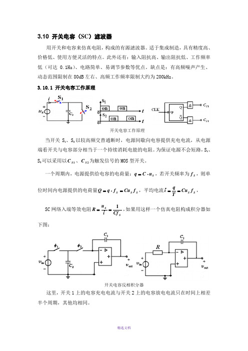
3.10 开关电容(SC )滤波器用开关和电容来仿真电阻,构成的有源滤波器。
适于集成制造,具有精度高、价格低、使用方便灵活的特点。
此外还有:输入阻抗高、输出阻抗低、工作频率低(可达0.1Hz )、电路简单、易调节参数等优点。
缺点是:有高频噪声产生、动态范围限制在80dB 左右、高频工作频率限制大约为200kHz 。
3.10.1 开关电容工作原理开关电容工作原理当开关S 1、S 2以较高频交替通断时,电源间歇向电容提供充电电流,从电源端看开关与电容部分相当于一个持续消耗电能的电阻。
为保证电源不会短路,S 1、S 2可以采用以1S C 、2S C 为触发信号的MOS 型开关。
一个周期内,电源提供给电容的电荷量:S u C q ⋅=,若开关频率为S f ,则单位时间内电源提供的电荷量S S S f Cu f q Q =⋅=,平均电流S S f Cu Tqi ==, SC 网络入端等效电阻SS Cf i u R 1==,如果用这样一个仿真电阻构成积分器如下图:开关电容反相积分器这里,开关1上的电容充电电流与开关2上的电容放电电流只在时间上相差半个周期,其他均相同。
s f CC C Cf s sRC s H S S1111)(111⋅-=⋅⋅-=-=,积分常数S f C C 11=τ,由于开关频率S f 可以调节,所以积分常数是可调的,并且积分常数由容量比决定,而不再与具体电容值有关。
在制造集成SC 滤波器时,所用到的器件(电容、电阻、开关等)均采用MOS 技术实现,简化了制造工艺,有利于提高集成度。
但是依赖于集成MOS 技术制造的电容,容量很难精确控制,误差会达到30%以上,不过依赖于同种制造工艺的电容,容量比却可以十分精确,精度可以达到0.1%以上。
因此,借助于SC 来实现电阻的集成滤波器,集成度高而且很精确。
当一个集成的通用滤波器器件内部需要用到多个SC 仿真电阻时, 每个仿真电阻都有一个S f 控制端,这样就衍生出了可编程SC 滤波器,不改变器件结构,通过编程指令改变滤波器的性能和参数。
三相 200V 栅极驱动器 CMS6164 用户手册说明书
CMS6164用户手册三相200V栅极驱动器Rev. 1.40请注意以下有关CMS知识产权政策*中微半导体(深圳)股份有限公司(以下简称本公司)已申请了专利,享有绝对的合法权益。
与本公司MCU或其他产品有关的专利权并未被同意授权使用,任何经由不当手段侵害本公司专利权的公司、组织或个人,本公司将采取一切可能的法律行动,遏止侵权者不当的侵权行为,并追讨本公司因侵权行为所受的损失、或侵权者所得的不法利益。
*中微半导体(深圳)股份有限公司的名称和标识都是本公司的注册商标。
*本公司保留对规格书中产品在可靠性、功能和设计方面的改进作进一步说明的权利。
然而本公司对于规格内容的使用不负责任。
文中提到的应用其目的仅仅是用来做说明,本公司不保证和不表示这些应用没有更深入的修改就能适用,也不推荐它的产品使用在会由于故障或其它原因可能会对人身造成危害的地方。
本公司的产品不授权适用于救生、维生器件或系统中作为关键器件。
本公司拥有不事先通知而修改产品的权利,对于最新的信息,请参考官方网站 目录1.产品概述 (3)1.1描述 (3)1.2功能特性 (3)1.3典型应用 (3)1.4订购信息 (3)2.管脚分布 (4)3.系统框图 (5)4.绝对最大额定值 (6)5.推荐工作条件 (7)6.电特性参数表 (8)7.典型应用电路图 (9)8.应用说明 (10)8.1自举电容 (10)8.2栅极驱动电阻 (10)8.3PCB注意事项 (11)9.测试说明 (12)9.1时间参数定义 (12)9.2逻辑时序图 (12)9.3VCC、VBS欠压时序图 (13)9.4瞬态负压安全工作区 (13)10.封装形式外形尺寸图 (14)10.1TSSOP20 (14)11.版本历史 (15)1. 产品概述2. 管脚分布3. 系统框图4. 绝对最大额定值5. 推荐工作条件6. 电特性参数表7. 典型应用电路图7) D1自举二极管,需耐压足够且恢复速度快;8) R6/D2以及R7/D3构成快关电路可提升关断速度优化寄生导通噪声。
cudk6型三相移相可控硅触发器说明书

cudk6型三相移相可控硅触发器说明书第一部分:引言1. 介绍主题:cudk6型三相移相可控硅触发器在工业控制领域,cudk6型三相移相可控硅触发器是一种常见的电力控制设备,它能够实现对三相交流电源的精确调节和控制。
本文将对cudk6型三相移相可控硅触发器进行深入探讨,分析其工作原理、特点和应用。
2. 背景信息在工业生产和电力系统中,对电源进行精确控制和调节是非常重要的,而cudk6型三相移相可控硅触发器正是为了满足这一需求而被广泛使用的。
它能够有效地调节电压和电流,保证设备稳定运行,同时也能提高能源利用率和生产效率。
第二部分:工作原理和特点3. 工作原理cudk6型三相移相可控硅触发器主要由三个单相可控硅组成,通过控制它们的触发角来实现对三相电源的调节。
当触发脉冲到来时,可控硅导通,从而实现对负载电压和电流的控制。
其工作原理相对简单,但却能够实现精确的电力调节。
4. 特点cudk6型三相移相可控硅触发器具有响应速度快、控制精度高、可靠性强等特点。
在工业生产和电力系统中,它能够实现对各种负载的精确调节,并且适用范围广泛。
第三部分:应用领域5. 工业生产应用在工业生产中,cudk6型三相移相可控硅触发器常常用于电动机的起动、调速和制动,以及对加热装置、电炉等负载的精确控制。
它能够提高设备的运行稳定性和效率,降低能耗,因此受到了广泛应用。
6. 电力系统应用在电力系统中,cudk6型三相移相可控硅触发器常用于电压和电流的调节和控制,能够提高系统的稳定性和可靠性,同时也能够提高能源利用率和降低能耗。
第四部分:个人观点和总结7. 个人观点在我看来,cudk6型三相移相可控硅触发器是一种非常重要的电力控制设备,它能够为工业生产和电力系统提供精确的电力调节,帮助提高系统的稳定性和效率。
随着工业自动化程度的不断提高,cudk6型三相移相可控硅触发器的应用将会更加广泛,对于促进工业生产和能源节约具有重要意义。
8. 总结cudk6型三相移相可控硅触发器作为一种重要的电力控制设备,在工业生产和电力系统中具有广泛的应用前景。
费斯托 MSE6-C2M 能效模块 说明书

火花点火控制器 F-35-62 说明书

F-35-62September 20201FEATURES•Dual Direct Spark Ignitors (DSI)•Single or Multiple tries for ignition (TFI)•Multiple options for ignition period, pre-purge, and inter-purge timings•Meets UL 60730-2-5 Harmonized Standard •Diagnostic Red LED •Flame Sense Yellow LED•Dual Local or Remote flame sensing •Quick connect terminals or Multi-pin header •Integral Brass Standoffs or Enclosure available •Available one-hour automatic reset •Communications and Alarm Out available •Fan Control Board availableAPPLICATIONS•Commercial Cooking •Radiant Heaters •Gas Furnaces •BoilersDESCRIPTIONThe Model 35-62 is a 24 VAC Microprocessor Based Dual DirectSpark Ignition Control designed for use in all types of heating and Commercial Cooking applications where the appliance has two burners. The control uses a microprocessor to continually and safely monitor, analyze and control the proper operation of the gas burner. A Fan Control Accessory Board is available and can be added if an inducer fan control is required.Agency CertificationsSPECIFICATIONSUL 60730-1 Automatic Electrical Controls - Part 1: General RequirementsUL 60730-2-5 Automatic Electrical Controls for Household and Similar Use, Part 2-5: Particular Requirements for Automatic Electrical Burner Control SystemsANSI Z21.20 Automatic Gas Ignition Systems and ComponentsCAN/CSA E60730-1 Automatic Electrical Controls - Part 1: General RequirementsCAN/CSA-C22.2 No. 60730-2-5 Automatic Electri-cal Controls for Household and Similar Use - Part 2-5: Particular Requirements for Automatic Elec-trical Burner Control Systems RoHS CompliantInput PowerControl: 18.0 to 30 VAC at 50/60 HZ ACInput Current 300 mA @ 24 VAC, gas valverelays energized @ 25°CGas Valve 2.0A @ 24 VAC(4.0A Inrush)Operating Temperature -40°F to + 176°F(-40°C to +80°C)Storage Temperature -40°F to + 185°F(-40°C to +85°C)Flame Sensitivity 0.7uA minimumFlame Failure Response Rate 0.8 seconds maximum Flame Failure Lockout Time Varies by model,270 seconds maximumFlame Detector Self-check Rate50/60 times per second Gas Types Natural, LP, or manufactured Spark Rate 25/30 sparks per second Size (LxWxH)Board Only 5.5 x 3.75 x 1.5 inches (13.97 x 9.53 x 3.8 cm)Size (LxWxH)with Cover 5.7 x 4.0 x 1.6 inches (14.45 x 10.15 x 4.1 cm)Enclosure / Mounting Noryl Gray Cover orIntegral standoffsMoisture Resistance Conformal coated to operate to95% R.H. (Non-Condensing) Avoid direct exposure to water.Ingress Protection Not Rated, Protection provided byappliance in which it is installed.Tries for Ignition One or Three Tries for Ignition Periods 4, 7, 10, or 15 seconds Pre-purge and Inter-purge Timings None, 15, or 30 seconds Without pre-purge, there is a 2 sec-ond start-up delay.Alarm modes and Communication Standard NC, True Alarm, or Fan Control.Optional UART communicationSERIES 35-62 "HARMONIZED"24 VAC Microprocessor BasedDirect Spark Ignition Control - Dual PointSEQUENCE OF OPERATION / FLAME RECOVERY / SAFETY LOCKOUTPower UpDuring power up the Red LED shall briefly flash ON for around 1 second while the control resets and then turns OFF to indicate normal operation.Start Up - Heat ModeWhen a call for heat is received from the thermostat, 24 VAC to TH, the control begins a pre-purge delay. Following the pre-purge period, the gas valve is energized and sparking commences at both electrodes for the Trial for Ignition (TFI) period.When both flames are detected during the TFI, the sparking process is terminated and the gas valve remains energized. The thermostat and burner flame are constantly monitored to assure proper system operation. When the thermostat is satisfied and the demand for heat ends, the gas valve is immediately de-energized.Failure to Light - LockoutSINGLE TRIAL MODELShould either burner fail to light, or a flame is not detected during the TFI period, the gas valve will de-energize and the control will go into lockout.MULTI TRIAL MODELShould either burner fail to light or the flame is not detected during the TFI period, the gas valve will de-energize. The control will then go through an inter-purge delay before an additional ignition attempt. The control attempts two additional ignition trials before de-energizing the gas valve and entering lockout. Flame Failure - Recycle ModeIf the established flame signal is lost from either burner the gas valve is de-energized and the control proceeds to inter-purge before attempting to relight the flame. Multi-try models permit three tries for ignition including inter-purges. If the burner relights, normal operation resumes. If the burner does not relight, the control will enter lockout.Lockout RecoveryRecovery from lockout requires a manual reset by either resetting the thermostat, or removing power for a period of 5 seconds. On models with automatic reset, if the thermostat is still calling for heat after one hour, then the control will automatically reset and attempt to ignite the burner.Fan Control Accessory (FCA) Board - OptionalThe FCA wired in conjunction with the 35-62 will provide fan power for the pre-purge and inter-purge times configured in the 35-62. The FCA also supports fan post-purge time after the call for heat is removed.MOUNTING AND WIRINGThe 35-62 is not position sensitive and can be mounted vertically or horizontally. The control may be mounted on any surface and fastened with #6 sheet metal screws. Secure the control in an area that will experience a minimum of vibration and remain below the maximum ambient temperature of 176°F (80°C). All connections should be made with UL approved, 105°C rated, 18 gauge stranded wire with .054" minimum insulation thick-ness. Refer to the appropriate wiring diagram when connecting the 35-62 to other components in the system.CAUTIONLabel all wires prior to disconnection whenservicing or replacing controls. Wiring errors cancause improper and dangerous operation. Afunctional checkout of a replacement controlshould always be performed.CAUTIONThe control must be mounted and located in amanner which protects components fromexposure to water (dripping, condensate,spraying, rain). Any control that has beenexposed to water must be replaced. WARNINGAll wiring must be done in accordance with bothlocal and national electrical code, and by atrained service technician. Wiring must be atleast #18 AWG /AWM rated for 105°C or higher. WARNINGThe 35-62 uses voltages of shock hazardpotential. Wiring and initial operation must bedone by qualified service technician. WARNINGOperation outside specifications could result infailure of the Fenwal Controls product and otherequipment with injury to people and property. WARNINGDo not disconnect any electrical loads while theautomatic gas ignition control is powered.Disconnect power prior to installation orreplacement of the control with the end useappliance.Effective: September 2020F-35-623TERMINAL DESIGNATIONSWIRING DIAGRAMSFigure 1. Local SenseFigure 2. Remote SenseDIMENSIONSFigure 3. Board OnlyFigure 4. Control with CoverFigure 5. Cover Side ViewHIGH VOLTAGE AND REMOTE SENSE CABLE REQUIREMENTSThe HV Ignition Cable should have a voltage rating of 25KV and an insulation rating of 200C. Suppression type UL 3257 or SAE J2031 ratings are recommended. Recommend length of 3ft (.9m) or less. Consult Fenwal Controls for longer lengths.Remote flame sense cable must meet a voltage rating of 250V and an insulation rating of 200 °C. Recommended length of 10ft (3m) or less. Consult Fenwal Controls for longer lengths.Refer to Fenwal Controls datasheet F-05-1000 for details.NameDescriptionTerminal TypeR Power1/4" male Q.C. GND Ground (Qty 2)3/16" male Q.C.V1Gas Valve 3/16" male Q.C. or .156 pin (2)V2Gas Valve GND 3/16" male Q.C. or .156 pin (3)NC/ALM NC Contact,Alarm Out, or FCA 1/4" male Q.C. or .156 pin (4)TH/W Thermostat1/4" male Q.C. or .156 pin (5)S1Remote Flame Sense 11/4" male Q.C. or .156 pin (1)S2Remote Flame Sense 21/4" male Q.C. or .156 pin (6)P3 Pin 1Comm. Transmit .100 pin P3 Pin 2Comm. Receive .100 pin P3 Pin 3GND Comm. GND.100 pin HV1 H.V. Spark 11/4" male Q.C.HV2H.V. Spark 21/4" male Q.C.SPARK ELECTRODES/FLAME SENSORSCritical for gas-fired appliances, proper design, construction, and application assures reliable ignition and optimal performance. Fenwal Controls recommends glazed Alumina ceramics and certified rod materials suitable up to 2550°F (1400°C). Spark electrodes typically have a 0.125" gap between the high voltage (HV) rod tip and the ground rod or burner. Flame sensors are a single rod used in flame rectification circuit of the ignition control to confirm the presence (or absence) of the flame. Refer to Fenwal Controls datasheet F-22-100 for details.Proper Electrode LocationProper location of electrode assembly is important for optimum system performance. The electrode assembly should be located so that the tips are inside the flame envelope and about 1/2-inch (1.2 cm) above the base of the flame as shown:Notes:•Ceramic insulators must not be in or close to the flame Electrode assemblies must not be adjusted or disassembled. Electrodes are NOT field adjustable.•Electrodes should have a gap spacing of 0.125± 0.031 in (3.12± 0.81 mm), unless otherwise specified by the appliance manufacturer. If spacing is not correct, the assembly must be replaced.•Exceeding temperature limits can cause nuisance lockouts and premature electrode failure.•Electrodes must be located where they are not easily accessible during normal operation.Flame Current MeasurementFlame current is the current which passes through the flame from the sensor to ground to complete the primary safety circuit. The minimum flame current necessary to keep the system from lockout is 0.7µA. A good burner ground that matches the control ground is critical for reliable flame sensing.There is no need to manually check flame current, the 35-62 is equipped with a Flame Current LED.Flame Current LEDFlame currents of the two channels are simultaneouslymonitored. The yellow LED provides current status for the lower flame strength out of the two burners.Note:LED will toggle on for 100ms and off for 300ms as needed to indicate a message. The code will repeat every 3.2 seconds.TROUBLESHOOTINGNote:During a fault condition, the LED will toggle on for 100ms and off for 300ms as needed to indicate the fault code. The code will repeat every 3.2 seconds. Removing power from the control will clear the fault code.Internal Control FailureIf the control detects a software or hardware error, all outputs are turned off. If this condition persists after an attempt to restart, then the control must be replaced.Flame Conditions – Yellow Flame Sense LED LED Indication Fault ModeOffNot in Burn mode5 flashes Low flame current (1uA or less)7 flashes Acceptable flame current (>1uA)WARNING Risk of Explosion or FireThe 35-62 control cannot be serviced by the user. If any control faults are detected, the 35-62 control must be replaced by qualified servicepersonnel. Risk of explosion or fire can result ifthe control module has been opened or with any attempts to repair it, and the warranty is void.Troubleshooting Guide SymptomRecommended Actions1. Control does not start,Dead A. Miswired B. Transformer bad/battery faultC. Fuse/circuit breaker faultD. No voltage at PWRE. Faulty control 2. Valve on, no sparkA. MiswiredB. Shorted electrodeC. Open HV cableD. Faulty control3. Spark on, no valveA. Valve coil openB. Open valve wireC. Faulty control(check voltage between V1 and V2)4. Flame okay during TFI, No flame sense (after TFI)A. Check electrode positionB. Check high voltage wireC. Poor ground at burnerD. Poor flame, check flame currentFault Conditions – Red diagnostic LED LED Indication Fault ModeOff Standby & Normal Condition Steady On Internal Control Failure 2 flashes False Flame 3 flashes Ignition LockoutThis literature is provided for informational purposes only. KIDDE-FENWAL, INC. assumes no responsibility for the prod-uct’s suitability for a particular application. The product must be properly applied to work correctly. If you need more informa-tion on this product, or if you have a particular problem or question, contact KIDDE-FENWAL, INC., Ashland, MA 01721.© 2020 Carrier P/N F-35-62 Rev AAFenwal Controls, Kidde-Fenwal Inc.400 Main Street Ashland, MA 01721Tel: 800-FENWAL-1Fax: 508-881-7619 All trademarks are property of their respective owners.EXPORT INFORMATION (USA)Jurisdiction: EAR Classification: EAR99This document contains technical data subject to the EAR.STANDARD PART NUMBER CONFIGURATIONNote:35-626999-XXX Uses Fenwal Control's advanced Option ID # for additional options. The XXX becomes the product’s unique identifier.。
MAX6675中文数据手册
热电偶开路检测
位 D2 一般情况下为 0,在热电偶开路时 跳变为 1。为了使热电偶开路检测器能够 正常运行,T-必须接地,且接地点需尽可 能靠近 GND 引脚。
温升的考虑
在某些应用中器件自身发热会降低 MAX6675 的精度。温度误差的大小取决于 MAX6675 封装的热传导性、安装技术、和 气流的影响。使用一个大的地平面可以提 高 MAX6675 的温度测量精度。
100
ns
100 ns
100 ns
100 ns
Note 1: 所有参数都是在 TA=25℃下 100%测试。温度超过极限 (TA = TMIN to TMAX) 的参 数只从设计和特性上保证,没有产品测试。 Note 2: 从设计上保证,没有产品测试。
(没有特别指出,VCC=+3.3V,TA=+25℃) 输出码误差和环境温度
使用适当的保护套保护热电偶
仅仅在低温、温度波动小的区域使用 补偿导线
保存事件日志和热电偶阻抗的记录
噪声方面的考虑
MAX6675 的精确度易受电源耦合噪声的影 响。电源噪声的影响可以通过放置 1 个 0.1μ F 的陶瓷电容消弱,电容应靠近器 件的电源引脚。
减小拾取噪声的影响
输入放大器(A1)是一个低噪声的放大器, 它被设计为能够放大高精度的传感器输入 信号。确保热电偶和与其想接的导线远离 电子噪声源。
可以用以下措施改善热电偶系统的测量精 度:
使用尽可能粗的导线,这样的导线不 至于从测量区域分流来大量的热
如果要求使用比较细的导线在,则仅 仅在测量区使用这种线,在没有温升 的地方使用补偿导线
多层陶瓷电容器

容量与温度关系图 1
20 COG
0
X7R -20
容量变化(%)
-40
Z5U
-60
-100
-50
0
50
温度(℃)
100
150
福州欧中电子有限公司
2
Tel:(0591)87871172/182 Fax:87809119
Email: eurocn@
福州欧中电子有限公司
1
Tel:(0591)87871172/182 Fax:87809119
Email: eurocn@
多层陶瓷电容器介质电特性
多层陶瓷电容器基本原理
电极
介质
±10% P ±15% R +22-56% U +22-82% V
介质分类
陶瓷电容一般是以其温度系数作为主要分类。 Class I - 一类陶瓷(超稳定)EIA 称之为 COG 或 NPO。工作温度范围 -55℃~+125℃,容量变化不 超过±30ppm/℃。电容温度变化时,容值很稳定, 被称作具有温度补偿功能,适用于要求容值在温度 变化范围内稳定和高 Q 值的线路以及各种谐振线 路。
端头
t
A
电容量的公式为: C = NKA/t
式中: C = 电容量 N = 电极层数 K = 介质常数(K 值) A = 相对电极覆盖面积 t = 电极间距(介质厚度)
采用多层技术生产陶瓷电容便可以实现大容 量小体积的需求,增大 N(增加层数)便可增大容 量。反观单层的电容,N 始终是 1,若再要提高容 量,必定采用高 K 值(降低稳定性能)、增加 A(增 大体积)或降低 t(降低耐电压能力)。
LCD 逆变器应用- FB9 系列..………………………………....................................……...........................31
- 1、下载文档前请自行甄别文档内容的完整性,平台不提供额外的编辑、内容补充、找答案等附加服务。
- 2、"仅部分预览"的文档,不可在线预览部分如存在完整性等问题,可反馈申请退款(可完整预览的文档不适用该条件!)。
- 3、如文档侵犯您的权益,请联系客服反馈,我们会尽快为您处理(人工客服工作时间:9:00-18:30)。
3.10 开关电容(SC )滤波器
用开关和电容来仿真电阻,构成的有源滤波器。
适于集成制造,具有精度高、
价格低、使用方便灵活的特点。
此外还有:输入阻抗高、输出阻抗低、工作频率低(可达0.1Hz )、电路简单、易调节参数等优点。
缺点是:有高频噪声产生、动态范围限制在80dB 左右、高频工作频率限制大约为200kHz 。
3.10.1 开关电容工作原理
开关电容工作原理
当开关S 1、S 2以较高频交替通断时,电源间歇向电容提供充电电流,从电源端看开关与电容部分相当于一个持续消耗电能的电阻。
为保证电源不会短路,S 1、S 2可以采用以1S C 、2S C 为触发信号的MOS 型开关。
一个周期内,电源提供给电容的电荷量:S u C q ⋅=,若开关频率为S f ,则单位时间内电源提供的电荷量S S S f Cu f q Q =⋅=,平均电流S S f Cu T
q
i ==
, SC 网络入端等效电阻S
S Cf i u R 1==,如果用这样一个仿真电阻构成积分器如下图:
开关电容反相积分器
这里,开关1上的电容充电电流与开关2上的电容放电电流只在时间上相差
半个周期,其他均相同。
s f C C C Cf s sRC s H S S
1
111
)(11
1
⋅-=⋅⋅-=-
=,积分常数S f C C 11=
τ,由于开关频率S f 可以调节,所以积分常数是可调的,并且积分常数由容量比决定,而不再与
具体电容值有关。
在制造集成SC 滤波器时,所用到的器件(电容、电阻、开关等)均采用MOS 技术实现,简化了制造工艺,有利于提高集成度。
但是依赖于集成MOS 技术制造的电容,容量很难精确控制,误差会达到30%以上,不过依赖于同种制造工艺的电容,容量比却可以十分精确,精度可以达到0.1%以上。
因此,借助于SC 来实现电阻的集成滤波器,集成度高而且很精确。
当一个集成的通用滤波器器件内部需要用到多个SC 仿真电阻时, 每个仿真电阻都有一个S f 控制端,这样就衍生出了可编程SC 滤波器,不改变器件结构,通过编程指令改变滤波器的性能和参数。
3.10.2 寄生电容问题
在SC 集成滤波器中,MOS 开关和电容的每个端子到地都有寄生电容存在,寄生电容的容量无法准确估计,有时寄生电容容量可以达到电容本身的10%,设计器件时应当尽量避免寄生电容对滤波器的性能及参数造成影响。
SC 反相积分器的寄生电容分布
1p C —开关S 1对地的寄生电容;
2p C —开关S 1、开关S 2、电容C 2的上极板对地寄生电容; 3p C —电容C 2下极板对地的寄生电容;
4p C —S 2和C 1上极板对地的寄生电容;5p C —C 1下极板对地寄生电容。
其中1p C 、3p C 、5p C 分别与输入电压源、短路线、输出端并联,对转移函
数无影响。
4p C 连接在“虚地”之间,在不考虑运放的非理想因素时,也无影响。
而2p C 与C 2并联,将影响积分常数。
1. 对寄生电容不敏感的反相积分器
对寄生电容不灵敏的反相积分器
与前例电路相似的由制造S 1、C 1、C 2带来的寄生电容因为不影响积分常数,所以未画出,图中只画出了由开关改造带来的新寄生电容21p p C C ''、,可见寄生电容21p p C C ''、对电容C 2的充电路径(S 1闭合时)和放电路径(S 2闭合时)均不产生影响,所以也不影响转移函数。
2. 对寄生电容不敏感的同相积分器——开关位置与反相积分器不同。
对寄生电容不灵敏的同相积分器
对积分环节而言,SC 构成的仿真电阻
R f C R S -=-=21等效
,S f sC C C R s s H 1
21)(1)(=--=
3. 差分积分器
可以使用叠加定理分析。
V 1单独作用时,V 2=0,积分器为反相积分;当V 2
单独作用时,V 1 =0,积分器是同相积分。
所以,
)()(121
2112212V V f sC C
V f sC C V f sC C s H S S S -=⋅-⋅=
4. 开关电容二阶通用滤波器
等效电路
其中1111111C K f C K R S '==
,1414411C K f C K R S '==,2
52551
1C K f C K R S '-=-=-
②节点:0)1()1(
31164
121=++++V sC C sK R V C sK R V o in ④节点:
02235
3
=++-o in V sC V C sK R V
2
54562
2
515223545
62
515
2234
65
21
253
2
1)(S S S S in o f K K f K K s s f K K f K K s s K K K K K s s K K K K s s K K K s K s K K s K K s V V s H +⋅++⋅+-=''+'⋅+''+'⋅+-='+⋅+''+⋅+'-==
式中K 参数均为电容比值,滤波器特征参数只与电容比有关。
540K K f S =ω,
4
56
5456560
1
,
K K K K K K K Q K K f Q
S ===ω,通过适当设计1K 、2K 、3K 可以实现不同种类的滤波器。
3.10.3 通用SC 滤波器
基本组成:运放级、求和级、两个SC 积分器(积分常数K 可以由时钟频率控制),内置开关S (可以由外部控制)。
有2个输入端子,3个输出端子。
通用集成SC 滤波器通过适当的外部连接可以实现各种不同的滤波特性。
使用非常灵活。
以外接反馈环路的不同分三种工作模式来讨论。
1. 工作模式一:从V 3、V 5引入到运放输入端的反馈,同时从V 6接负反馈到求和级。
2. 工作模式二:在模式一的基础上,再增加从V6到运放输入端的反馈。
3. 工作模式三:在工作模式二基础上去掉求和级反馈。
4. 工作模式四:改变输入信号接法
例:分析工作模式4—(1)的转移函数。
5
64
56345
32123V s
K V V s K
V V V V V V R R
V R R V in in ==--=--=→
B P F
)1()(L P F
)1(
)(2
3
221
2552
3
2221
2
66⇒⇒+⋅++⋅-==
⇒⇒+⋅++-==
K K R R
s s K R R
s V V s H K K R R
s s K R R V V s H in
in
⎥⎥
⎥⎥
⎥⎦
⎤⎢⎢⎢⎢⎢⎣⎡+⋅++⎥⎦⎤⎢⎣⎡+-+-=+⋅++⋅-⋅--==2
3222
12313221
2
2
3
2212321233)1()1()(K K R R s s K Ks R R R R R R s R R
K K R R s s K
R R
s R R R R V V s H in 当32123132)1(R R R R R R R R -=⎥⎦
⎤⎢⎣⎡+-时,即:122
12--=
R R 时,可以实现APF 。