基于solidworks机床夹具设计外文翻译详解
SolidWorks的基础-毕业设计外文翻译

SolidWorks basisThis chapter pointsWith the PC, and the rapid development of CAD technology, in the past only in workstation environments, UNIX platform 3D design software applications, it is now the ordinary PC platform and the use of the Windows environment, become ordinary designers, engineers design tools. SolidWorks as a Windows environment of mechanical design software, has fully with the Windows user-friendly, simple operation of the characteristics of its powerful design features to satisfy the vast majority of mechanical product design needs.SolidWorks as a three-dimensional design software, a comprehensive parts and assembly modeling capabilities entities, and the model for analysis and processing, which automatically generate engineering drawings. In studying specific operations, it must first be correctly installed software to a computer, and then work with SolidWorks user interface, and by setting options to build a suitable working environment.This chapter includes:3D design software outlinedThe main features of SolidWorksInstallation and start SolidWorksSolidWorks user interfaceSet up the working environment of SolidWorks1.1 Summary of 3D design softwareCAD software category from the 20th century to the 1960s computer-aided geometric design was mainly to resolve the graphics on the computer display and describe the problem, then gradually raised wireframe, surface, geometric entities such as physical description model. Today, a total experienced the following stage.computer graphics stages: focused on solving computer graphics, surface expression, and other basic issues.technical parameters and characteristics of the stage: resolving CAD data control and modification.intelligent design stages: in the design of integrating more engineering knowledge and rules, to achieve a higher level of the computer-aided design.After 40 years of development, 3D design software has been developed from a simple drawings or product model generation tools, development can provide a wide range of engineering support, covering design intent expression of design standardization, serialization, and design results of the analysis can be created, interfere with the inspection process of judgement, design optimization, and many other aspects. 3D design the model can be converted to support CAE (computer-aided engineering) and CAM (computer-aided manufacturing) applications data format. 3D design these features meet the needs of the project, which have greatly increased the quality of product development and efficiency, greatly reducing the product design and development cycle.At present, large-scale manufacturing enterprises at home and abroad, the 3-D design software has been widely used. American companies such as Boeing use 3D designand related software, in the two and a half years, achieving the 777 non-design drawings. According to the traditional design work, the whole process requires at least four years. The company also works in the implementation of the widely used parallel engineering technology, in the CAD environment with the overall product virtual assembly, the number of correct design errors, thus ensuring that the design process of the short cycle, the outcome of the high-quality design and manufacturing process the fluency.The extensive use of three-dimensional design software can be divided into high-end and mid-range CAD systems, the high-end 3D CAD software mainly I-DEAS, UG, Pro / ENgineeR, CATIA, mid-range 3D CAD system mainly SolidWorks, SolidEdges, MDT, Inventor, etc.. The general manufacturing enterprises, and the powerful features of SolidWorks to complete the general design task, and it is its ease of use and efficiency has also aroused the concern of more and more users.3D design software experience from simple geometric model generation tools to technology to variable control of the product model, ultimately forming a complete enterprise digital process. 3D design software applications greatly enhance the efficiency of product design and development.Compared to 2D design (CAD), the biggest feature of the 3D design feature is the use of modeling techniques and the entire design process related technologies. 3D design software is not only a powerful modeling functions, but also provides a wide range of engineering support. Including a description of the design intent, design and design reuse, such as serialization.3D design into part design, assembly design and engineering drawings generated three stages. Related to the entire design process, makes any stage revised design will affect the other results of the design stage, thus maintaining the model in a variety of consistency in the design environment, thus improving design efficiency.1.1.1 Part DesignParts design is the basis of three-dimensional design. Parts are generally in the form of three-dimensional entities, as shown in Figure 1.1 for loading vehicles in the "bucket" model of spare parts. Parts entities from the point of view of modeling, parametric feature-based modeling and 3-D design has become a mainstream technology. In different parts of the processing entity known as the characteristics of different combinations of features on the formation of a three-dimensional solid model parts. Not only has the characteristics of the corresponding projects, but also through the topological relations between the characteristics and timing relations can be flexible control of modeling results.Parts of the three-dimensional solid model, in the design and manufacturing process to achieve the following features.generate engineering drawings parts.parts of the stress analysis and strength check.formed assembly, test the reasonableness of the design.formation of mold parts.generated NC code, direct machining.Figure 1.1 loader "bucket" model parts1.1.2 assembly design3D design software assembly is the basic function of one. Figure 1.2 shows the toys "loader" assembly model. In modern design, can make use of the existing three-dimensional model parts will be two or more parts in accordance with certain constraints relationship assembly, formation of virtual product assembly; also can be used to project more in line with the top-down assembly design approach , in the assembly environment, in reference to other parts of the assembly of the location and size of the design of the new parts and assembly. At the same time, the assembly has been expanded to more engineering fields, such as motion analysis, interference checking, etc.. 3D design software product assembly environment has become the basis for comprehensive performance verification environment.The use of virtual product assembly model, the following functions can be realized.a product of the true effect maps, verify that the product structure, analysis and design.products generated view of the explosion.the product movement analysis and dynamic simulation depicts moving parts specific point trajectory.the real effect of the product plans for the "conceptual design products."products generated simulation animation, presentation products assembly process. Figure 1.2 toys "loader" assembly model1.1.3 Engineering Graphics GenerationUse of parts and assembly solid model can be automatically generated assembly of parts and 2D engineering drawings. And compared to traditional CAD, 3D design software engineering drawings generated much simpler to operate, only specified model projection direction, insert size, and then details can be set up engineering drawings. Figure 1.3 shows the SolidWorks automatically generated as shown in Figure 1.1 and the "bucket" parts of the corresponding engineering drawings.Figure 1.3 "bucket" Engineering GraphicsSolidWorks 1.2 featuresSolidWorks is a Windows environment of 3D mechanical design software, it has the following characteristics.1. Simple, easy to learn and usesimple interface to facilitate the work.full support for Windows drag copying, and mobile technology for the characteristics of the shear, copy, paste and other operations.use SolidWorks help system can quickly grasp design method.localization using core, the whole Chinese language interface.2. Clear intuitive dynamic interfacedynamic tagging using different colours, and the parameters of the current operation remind designers objects can be marked so that designers are able to set in thegraphics features of the relevant parameters; mouse confirmed and rich quick menu design makes very easy parts ; characteristics of the establishment, regardless of what position the mouse pointer, and can be quickly set up a feature.District dynamic graphics preview features make the design process can be easily clear look at the design reasonable.pioneering features Manager will be able to record and process design of a tree FeatureManager design, enables designers can easily achieve management features of the management of spare parts and assembly and modification.dynamic activation attributes Manager can be very easy to attribute the Show Manager, modify such an operation.use of the property managers to reduce the dialog graphics, making the design more concise, crisp.configuration management provides the establishment and revision of the form of parts or assembly operations.3. Flexible sketching and inspection functionssketching state and characteristics have tended to define clearly marked, allowing designers easily identify the current operating state.sketching easy to use click - click or click - Drag draft drawn in two ways, in line with the general design habits.make sketches in the process of dynamic feedback and reasoning can be automatically added geometric constraint conditions, the draft of the use of different colors to distinguish the definition of reality draft status.can drag yuan draft plans to change graphics and numerical size and geometry. drawing can be used for pipeline design or scan three-dimensional characteristics of the draft.4. Powerful feature-based modeling of parts and assembly controlpowerful solid modeling functions.can easily achieve the dynamic characteristics and the draft revision.function of the sheet metal-forming tools makes use of simple drag function can establish sheet metal parts used shape.use Feature Palette window, simply drag characteristics can be set up quickly; management and use of the feature is very convenient.use of spare parts and assembly configurations can be achieved not only the existing design, build enterprise portfolio, but also enables the design of products.driven by Excel software components and configuration automatically generated assembly configuration.use of the light assembly functions can be quickly and efficiently to deal with large-scale assembly.can be animated and dynamic view of the assembly assembly movement. achievable in the assembly of intelligent assembly, the assembly can also be dynamic interference checking and clearance testing, as well as static interference checking.system provides both the bottom-up assembly, also provides top-down assembly method. This method allows engineers to assembly in the assembly in reference to theenvironment in other parts of the assembly of the location and size of the design of new parts, more in line with projects habits.5. Dynamic model associated engineering drawings generation capabilitiesuse RapidDraft (Drawing) engineering drawings, engineering drawings and can be three-dimensional model of a separate operation, so as to speed up the operation of engineering drawings.can always maintain a three-dimensional model with the view of the shape and size of the entire relationship.3D model can be automatically generated view of the project.flexible view of operations, can generate projection view and cross-section of local enlarged view.6. Easy data exchangethrough standard data formats and other CAD data exchange software.provide diagnostic data input function, which allows users to input geometric entities in the implementation of simplified, model error, as well as re-established remove redundant topology.to provide a free plug-in the form of the data interface can be easily with other 3D design software (such as Pro / ENGINEER, UG, MDT, SolidEdges, etc.) data exchange.DWG / DXF file conversion wizard can be established by other software engineering graphics file conversion of engineering drawings into SolidWorks document.3D model can be exported into standard data formats, engineering drawings can also be output as DWG / DXF file format.7. Supported collaborative work3D Meeting is based on Microsoft's NetMeeting technology developed specifically for SolidWorks design staff to work together to provide the environment. 3 D Meeting can be used through the network of real-time collaborative work.support Web directory, design data can be stored in the folder, as in the local hard disk storage as easy.8. Facilitate the development of expansionProvide a free, open, full-featured API interface development tools, according to the actual situation of Visual C + +, Visual Basic, VBA or other OLE development process secondary development of SolidWorks.9. Support network exchangeSolidWorks design with the new products can be released into the Internet, so that is not installed SolidWorks customers via a Web browser to view it very easy for the remote release of new products and exchanges.10. Rich 3D performance meansSolidWorks provide animation features, AVI file can be generated.SolidWorks through plug-in enables users to easily produce high-quality PhotoWorks rendering map, including a wealth of material and texture, user-definable lighting, reflection, transparency, and background settings.11. Facilitate the engineering analysisSolidWorks has many plug-in, engineers can provide a wide range of engineering analysis tools, such as finite element method can be used for rapid stress, deformation, frequency, thermal efficiency, power, fatigue, and electromagnetic engineering analysis of a number of items of COSMOS / Works, Motion analysis of the agency Mechanical Dynamics, which can carry out the analysis of the heat FloWorks such as plug-ins can not only make use of SolidWorks 3D solid modeling, but also enables the software to become a powerful computer-aided engineering analysis tools. SolidWorks的基础本章要点随着个人电脑和CAD技术的飞速发展,过去只有在工作站环境中,UNIX平台的三维设计软件,它是目前普通PC平台和Windows环境下使用,成为普通的设计师,工程师的设计工具。
夹具设计外文翻译

Application and developmentOf case based reasoning in fixture designFixtures are devices that serve as the purpose of holding the workpiece securely and accurately, and maintaining a consistent relationship with respect to the tools while machining. Because the fixture structure depends on the feature of the product and the status of the process planning in the enterprise, its design is the bottleneck during manufacturing, which restrains to improve the efficiency and leadtime. And fixture design is a complicated process, based on experience that needs comprehensive qualitative knowledge about a number of design issues including workpiece configuration, manufacturing processes involved, and machining environment. This is also a very time consuming work when using traditional CAD tools (such as Unigraphics, CATIA or Pro/E), which are good at performing detailed design tasks, but provide few benefits for taking advantage of the previous design experience and resources, which are precisely the key factors in improving the efficiency. The methodology of case based reasoning (CBR) adapts the solution of a previously solved case to build a solution for a new problem with the following four steps: retrieve, reuse, revise, and retain [1]. This is a more useful method than the use of an expert system to simulate human thought because proposing a similar case and applying a few modifications seems to be self explanatory and more intuitive to humans .So various case based design support tools have been developed for numerous areas[2-4], such as in injection molding and design, architectural design, die casting die design, process planning, and also in fixture design. Sun used six digitals to compose the index code that included workpiece shape, machine portion, bushing, the 1st locating device, the 2nd locating device and clamping device[5]. But the system cannot be used for other fixture types except for drill fixtures, and cannot solve the problem of storage of the same index code that needs to be retained, which is very important in CBR[6].1. Construction of a Case Index and Case Library1.1 Case indexThe case index should be composed of all features of the workpiece, which are distinguished from different fixtures. Using all of them would make the operation in convenient. Because the forms of the parts are diverse, and the technology requirements of manufacture in the enterprise also develop continuously, lots of features used as the case index will make the search rate slow, and the main feature unimportant, for the reason that the relative weight which is allotted to every feature must diminish. And on the other hand, it is hard to include all the features in the case index.1.2 Hierarchical form of CaseThe structure similarity of the fixture is represented as the whole fixture similarity, components similarity and component similarity. So the whole fixture case library, components case library, component case library of fixture are formedcorrespondingly. Usually design information of the whole fixture is composed of workpiece information and workpiece procedure information, which represent the fixture satisfying the specifically designing function demand. The whole fixture case is made up of function components, which are described by the function components’ names and numbers. The components case represents the members. (function component and other structure components,main driven parameter, the number, and their constrain relations.) The component case (the lowest layer of the fixture) is the structure of function component and other components. In the modern fixture design there are lots of parametric standard parts and common non standard parts. So the component case library should record the specification parameter and the way in which it keeps them.2. Strategy of Case RetrievalIn the case based design of fixtures ,the most important thing is the retrieval of the similarity, which can help to obtain the most similar case, and to cut down the time of adaptation. According to the requirement of fixture design, the strategy of case retrieval combines the way of the nearest neighbor and knowledge guided. That is, first search on depth, then on breadth; the knowledge guided strategy means to search on the knowledge rule from root to the object, which is firstly searched by the fixture type, then by the shape of the workpiece, thirdly by the locating method. For example, if the case index code includes the milling fixture of fixture type, the search is just for all milling fixtures, then for box of workpiece shape, the third for 1plane+ 2pine of locating method. If there is no match of it, then the search stops on depth, and returns to the upper layer, and retrieves all the relative cases on breadth.2.1 Case adaptationThe modification of the analogical case in the fixture design includes the following three cases:1) The substitution of components and the component;2) Adjusting the dimension of components and the component while the form remains;3) The redesign of the model.If the components and component of the fixture are common objects, they can be edited, substituted and deleted with tools, which have been designed.2.2 Case storageBefore saving a new fixture case in the case library, the designer must consider whether the saving is valuable. If the case does not increase the knowledge of the system, it is not necessary to store it in the case library. If it is valuable, then the designer must analyze it before saving it to see whether the case is stored as a prototype case or as reference case. A prototype case is a representation that can describe the main features of a case family. A case family consists of those cases whose index codes have the same first 13 digits and different last three digits in the case library. The last three digits of a prototype case are always “000”. A reference case belongs to the same family as the prototype case and is distinguished by the different last three digits.From the concept that has been explained, the following strategies are adopted:1) If a new case matches any existing case family, it has the same first 13 digits as an existing prototype case, so the case is not saved because it is represented well by the prototype case. Or is just saved as a reference case (the last 3 digits are not “000”, and not the same with others) in the case library.2) If a new case matches any existing case family and is thought to be better at representing this case family than the previous prototype case, then the prototype case is substituted by this new case, and the previous prototype case is saved as a reference case.3) If a new case does not match any existing case family, a new case family will be generated automatically and the case is stored as the prototype case in the case library.3. ConclusionCBR, as a problem solving methodology, is a more efficient method than an expert system to simulate human thought, and has been developed in many domains where knowledge is difficult to acquire. The advantages of the CBR are as follows: it resembles human thought more closely; the building of a case library which has self learning ability by saving new cases is easier and faster than the building of a rule library; and it supports a better transfer and explanation of new knowledge that is more different than the rule library. A proposed fixture design framework on the CBR has been implemented by using Visual C ++, UG/Open API in U n graphics with Oracle as database support, which also has been integrated with the 32D parametric common component library, common components library and typical fixture library. The prototype system, developed here, is used for the aviation project, and aids the fixture designers to improve the design efficiency and reuse previous design resources.基于事例推理的夹具设计研究与应用夹具是以确定工件安全定位准确为目的的装置,并在加工过程中保持工件与刀具或机床的位置一致不变。
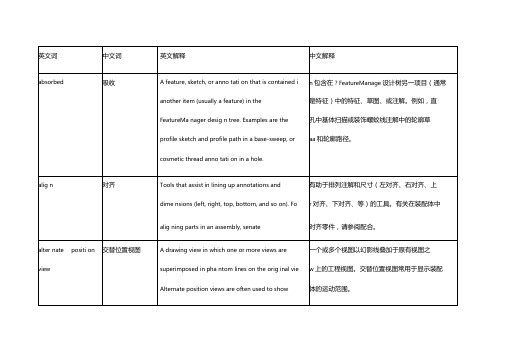
Solidworks术语中英文对照
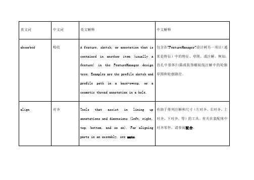
blend
混合
Seefillet.
请参阅圆角。
block
块
A user-defined annotation that you can use in parts, assemblies, and drawings. A block can contain text, sketch entities (except points), and area hatch, and it can be saved in a file for later use as, for example, a custom callout or a company logo.
给零件、装配体或工程图添加特定设计意图的文字摘要或符号。特定类型的注解包括注释、孔标注、表面粗糙度符号、基准特征符号、基准目标、形位公差符号、焊接符号、零件序号以及层叠零件序号。只应用于工程图的注解包括中心符号线、注解中心线、区域剖面线以及块。
appearance callouts
外观标注
Callouts that display the colors and textures of the face, feature, body, and part under the entity selected and are a shortcut to editing colors and textures.
在装配体中标注零件,通常包括一项目号和数量。在工程图中,项目号与材料明细表(BOM)中的行数关联。另请参阅成组的零件序号。
base
基体
The first solid feature of a part.
零件的第一个实体特征。
机械加工工艺装备夹具外文文献翻译、中英文翻译、外文翻译

外语文献翻译摘自: 《制造工程与技术(机加工)》(英文版)《Manufacturing Engineering and Technology —Machining 》机械工业出版社 2004年3月第1版 页—564560P美 s. 卡尔帕基安(Serope kalpakjian)s.r 施密德(Steven R.Schmid) 著原文:20.9 MACHINABILITYThe machinability of a material usually defined in terms of four factors:1、Surface finish and integrity of the machined part; 2、Tool life obtained; 3、Force and power requirements; 4、 Chip control.Thus, good machinability good surface finish and integrity, long tool life, and low force And power requirements. As for chip control, long and thin (stringy) cured chips, if not broken up, can severely interfere with the cutting operation by becoming entangled in the cutting zone.Because of the complex nature of cutting operations, it is difficult to establish relationships that quantitatively define the machinability of a material. Inmanufacturing plants, tool life and surface roughness are generally considered to be the most important factors in machinability. Although not used much any more, approximate machinability ratings are available in the example below.20.9.1 Machinability Of SteelsBecause steels are among the most important engineering materials (as noted in Chapter 5), their machinability has been studied extensively. The machinability of steels has been mainly improved by adding lead and sulfur to obtain so-called free-machining steels.Resulfurized and Rephosphorized steels. Sulfur in steels forms manganese sulfide inclusions (second-phase particles), which act as stress raisers in the primaryshear zone. As a result, the chips produced break up easily and are small; this improves machinability. The size, shape, distribution, and concentration of these inclusions significantly influence machinability. Elements such as tellurium and selenium, which are both chemically similar to sulfur, act as inclusion modifiers in resulfurized steels.Phosphorus in steels has two major effects. It strengthens the ferrite, causing increased hardness. Harder steels result in better chip formation and surface finish. Note that soft steels can be difficult to machine, with built-up edge formation and poor surface finish. The second effect is that increased hardness causes the formation of short chips instead of continuous stringy ones, thereby improving machinability.Leaded Steels. A high percentage of lead in steels solidifies at the tip of manganese sulfide inclusions. In non-resulfurized grades of steel, lead takes the form of dispersed fine particles. Lead is insoluble in iron, copper, and aluminum and their alloys. Because of its low shear strength, therefore, lead acts as a solid lubricant (Section 32.11) and is smeared over the tool-chip interface during cutting. This behavior has been verified by the presence of high concentrations of lead on thetool-side face of chips when machining leaded steels.When the temperature is sufficiently high-for instance, at high cutting speeds and feeds (Section 20.6)—the lead melts directly in front of the tool, acting as a liquid lubricant. In addition to this effect, lead lowers the shear stress in the primary shear zone, reducing cutting forces and power consumption. Lead can be used in every grade of steel, such as 10xx, 11xx, 12xx, 41xx, etc. Leaded steels are identified by the letter L between the second and third numerals (for example, 10L45). (Note that in stainless steels, similar use of the letter L means “low carbon,” a condition that improves their corrosion resistance.)However, because lead is a well-known toxin and a pollutant, there are serious environmental concerns about its use in steels (estimated at 4500 tons of lead consumption every year in the production of steels). Consequently, there is a continuing trend toward eliminating the use of lead in steels (lead-free steels). Bismuth and tin are now being investigated as possible substitutes for lead in steels.Calcium-Deoxidized Steels. An important development is calcium-deoxidized steels, in which oxide flakes of calcium silicates (CaSo) are formed. These flakes, in turn, reduce the strength of the secondary shear zone, decreasing tool-chip interfaceand wear. Temperature is correspondingly reduced. Consequently, these steels produce less crater wear, especially at high cutting speeds.Stainless Steels. Austenitic (300 series) steels are generally difficult to machine. Chatter can be s problem, necessitating machine tools with high stiffness. However, ferritic stainless steels (also 300 series) have good machinability. Martensitic (400 series) steels are abrasive, tend to form a built-up edge, and require tool materials with high hot hardness and crater-wear resistance. Precipitation-hardening stainless steels are strong and abrasive, requiring hard and abrasion-resistant tool materials.The Effects of Other Elements in Steels on Machinability. The presence of aluminum and silicon in steels is always harmful because these elements combine with oxygen to form aluminum oxide and silicates, which are hard and abrasive. These compounds increase tool wear and reduce machinability. It is essential to produce and use clean steels.Carbon and manganese have various effects on the machinability of steels, depending on their composition. Plain low-carbon steels (less than 0.15% C) can produce poor surface finish by forming a built-up edge. Cast steels are more abrasive, although their machinability is similar to that of wrought steels. Tool and die steels are very difficult to machine and usually require annealing prior to machining. Machinability of most steels is improved by cold working, which hardens the material and reduces the tendency for built-up edge formation.Other alloying elements, such as nickel, chromium, molybdenum, and vanadium, which improve the properties of steels, generally reduce machinability. The effect of boron is negligible. Gaseous elements such as hydrogen and nitrogen can have particularly detrimental effects on the properties of steel. Oxygen has been shown to have a strong effect on the aspect ratio of the manganese sulfide inclusions; the higher the oxygen content, the lower the aspect ratio and the higher the machinability.In selecting various elements to improve machinability, we should consider the possible detrimental effects of these elements on the properties and strength of the machined part in service. At elevated temperatures, for example, lead causes embrittlement of steels (liquid-metal embrittlement, hot shortness; see Section 1.4.3), although at room temperature it has no effect on mechanical properties.Sulfur can severely reduce the hot workability of steels, because of the formation of iron sulfide, unless sufficient manganese is present to prevent such formation. Atroom temperature, the mechanical properties of resulfurized steels depend on the orientation of the deformed manganese sulfide inclusions (anisotropy). Rephosphorized steels are significantly less ductile, and are produced solely to improve machinability.20.9.2 Machinability of Various Other MetalsAluminum is generally very easy to machine, although the softer grades tend to form a built-up edge, resulting in poor surface finish. High cutting speeds, high rake angles, and high relief angles are recommended. Wrought aluminum alloys with high silicon content and cast aluminum alloys may be abrasive; they require harder tool materials. Dimensional tolerance control may be a problem in machining aluminum, since it has a high thermal coefficient of expansion and a relatively low elastic modulus.Beryllium is similar to cast irons. Because it is more abrasive and toxic, though, it requires machining in a controlled environment.Cast gray irons are generally machinable but are. Free carbides in castings reduce their machinability and cause tool chipping or fracture, necessitating tools with high toughness. Nodular and malleable irons are machinable with hard tool materials.Cobalt-based alloys are abrasive and highly work-hardening. They require sharp, abrasion-resistant tool materials and low feeds and speeds.Wrought copper can be difficult to machine because of built-up edge formation, although cast copper alloys are easy to machine. Brasses are easy to machine, especially with the addition pf lead (leaded free-machining brass). Bronzes are more difficult to machine than brass.Magnesium is very easy to machine, with good surface finish and prolonged tool life. However care should be exercised because of its high rate of oxidation and the danger of fire (the element is pyrophoric).Molybdenum is ductile and work-hardening, so it can produce poor surface finish. Sharp tools are necessary.Nickel-based alloys are work-hardening, abrasive, and strong at high temperatures. Their machinability is similar to that of stainless steels.Tantalum is very work-hardening, ductile, and soft. It produces a poor surfacefinish; tool wear is high.Titanium and its alloys have poor thermal conductivity (indeed, the lowest of all metals), causing significant temperature rise and built-up edge; they can be difficult to machine.Tungsten is brittle, strong, and very abrasive, so its machinability is low,although it greatly improves at elevated temperatures.Zirconium has good machinability. It requires a coolant-type cutting fluid,however, because of the explosion and fire.20.9.3 Machinability of Various MaterialsGraphite is abrasive; it requires hard, abrasion-resistant, sharp tools.Thermoplastics generally have low thermal conductivity, low elastic modulus, and low softening temperature. Consequently, machining them requires tools with positive rake angles (to reduce cutting forces), large relief angles, small depths of cut and feed, relatively high speeds, andproper support of the workpiece. Tools should be sharp.External cooling of the cutting zone may be necessary to keep the chips from becoming “gummy” and sticking to the tools. Cooling can usually be achieved with a jet of air, vapor mist, or water-soluble oils. Residual stresses may develop during machining. To relieve these stresses, machined parts can be annealed for a period of time at temperatures ranging from C ︒80 to C ︒160 (F ︒175to F ︒315), and then cooled slowly and uniformly to room temperature.Thermosetting plastics are brittle and sensitive to thermal gradients duringcutting. Their machinability is generally similar to that of thermoplastics.Because of the fibers present, reinforced plastics are very abrasive and aredifficult to machine. Fiber tearing, pulling, and edge delamination are significant problems; they can lead to severe reduction in the load-carrying capacity of the component. Furthermore, machining of these materials requires careful removal of machining debris to avoid contact with and inhaling of the fibers.The machinability of ceramics has improved steadily with the development of nanoceramics (Section 8.2.5) and with the selection of appropriate processing parameters, such as ductile-regime cutting (Section 22.4.2).Metal-matrix and ceramic-matrix composites can be difficult to machine, depending on the properties of the individual components, i.e., reinforcing or whiskers, as well as the matrix material.20.9.4 Thermally Assisted MachiningMetals and alloys that are difficult to machine at room temperature can be machined more easily at elevated temperatures. In thermally assisted machining (hot machining), the source of heat—a torch, induction coil, high-energy beam (such as laser or electron beam), or plasma arc—is forces, (b) increased tool life, (c) use of inexpensive cutting-tool materials, (d) higher material-removal rates, and (e) reduced tendency for vibration and chatter.It may be difficult to heat and maintain a uniform temperature distribution within the workpiece. Also, the original microstructure of the workpiece may be adversely affected by elevated temperatures. Most applications of hot machining are in the turning of high-strength metals and alloys, although experiments are in progress to machine ceramics such as silicon nitride.SUMMARYMachinability is usually defined in terms of surface finish, tool life, force and power requirements, and chip control. Machinability of materials depends not only on their intrinsic properties and microstructure, but also on proper selection and control of process variables.译文:20.9 可机加工性一种材料的可机加工性通常以四种因素的方式定义:1、分的表面光洁性和表面完整性。
机床基础机械加工工艺夹具类外文翻译、中英文翻译、外文文献翻译

外文翻译专业机械设计制造及自动化学生姓名孙道德班级BMZ机制031学号0361440120指导教师刘必荣附件1:机床基础范云涨著孙道德译摘要:在许多情况下初步加工成型的产品必须在尺寸和表面光洁度方面经过进一步的加工以满足设计要求。
为了满足这么高要求的尺寸,去除少量的材料是必需的。
机床通常用于执行这样的操作。
关键字:机床;车床机床介绍:机床加工作为产生形状的一种方法是所有制造过程中最普遍使用的并且是最重要的方法。
机床加工是一种成型的过程通过电机驱动,材料以切屑的形式被去除。
大多数的机床加工是通过既支承工件又支承刀具的装备来完成。
尽管在某些场合,工件无支承情况下,使用移动式装备来实现加工。
小批量生产低费用。
机床加工在制造过程中有两个方面。
对于铸造、锻造和压力加工,每一个要生产的具体工件形状,即使是一个零件,几乎都要花费高额的加工费用。
靠焊接来产生的结构形状,在很大程度上取决于有效的原材料的形状。
一般来说,通过利用贵重设备而又无需特种加工条件下,几乎可以从任何种类原材料开始,借助机床加工把原材料加工成任意所要求的结构形状,只要外部尺寸足够大,那都是可能的。
因此对于生产一个零件,通常选择机床加工甚至于当零件结构及要生产的批量大小上按理都适于用铸造、锻造或压力加工来生产的。
高的精度和良好表面光洁度。
机械加工的第二方面用途是建立在高精度和可能的表面光洁度基础上。
许多零件,如果用别的其他方法来生产属大批量生产的话,那么在机械加工中则是属低公差且又能满足要求的小批量生产了。
另方面,许多零件靠较粗的生产加工工艺提供其一般表面形状,而仅仅是在需要高精度的且选择过的表面上才进行机械加工。
例如内螺纹,除了机械加工之外,几乎没有别的加工方法能进行加工。
再如已锻工件上的小孔加工,也是在被锻后进行机械加工才完成的。
在美国材料切削业是一个很大的产业——费用每年超过36×109美元,包括材料,劳动力,管理费,机床装运费等所花的费用。
机床——机械类外文文献翻译、中英文翻译
毕业设计(论文)外文资料翻译系部:专业:姓名:学号:外文出处:English For Electromechanical(用外文写)Engineering附件:1.外文资料翻译译文;2.外文原文。
附件1:外文资料翻译译文机床机床是用于切削金属的机器。
工业上使用的机床要数车床、钻床和铣床最为重要。
其它类型的金属切削机床在金属切削加工方面不及这三种机床应用广泛。
车床通常被称为所有类型机床的始祖。
为了进行车削,当工件旋转经过刀具时,车床用一把单刃刀具切除金属。
用车削可以加工各种圆柱型的工件,如:轴、齿轮坯、皮带轮和丝杠轴。
镗削加工可以用来扩大和精加工定位精度很高的孔。
钻削是由旋转的钻头完成的。
大多数金属的钻削由麻花钻来完成。
用来进行钻削加工的机床称为钻床。
铰孔和攻螺纹也归类为钻削过程。
铰孔是从已经钻好的孔上再切除少量的金属。
攻螺纹是在内孔上加工出螺纹,以使螺钉或螺栓旋进孔内。
铣削由旋转的、多切削刃的铣刀来完成。
铣刀有多种类型和尺寸。
有些铣刀只有两个切削刃,而有些则有多达三十或更多的切削刃。
铣刀根据使用的刀具不同能加工平面、斜面、沟槽、齿轮轮齿和其它外形轮廓。
牛头刨床和龙门刨床用单刃刀具来加工平面。
用牛头刨床进行加工时,刀具在机床上往复运动,而工件朝向刀具自动进给。
在用龙门刨床进行加工时,工件安装在工作台上,工作台往复经过刀具而切除金属。
工作台每完成一个行程刀具自动向工件进给一个小的进给量。
磨削利用磨粒来完成切削工作。
根据加工要求,磨削可分为精密磨削和非精密磨削。
精密磨削用于公差小和非常光洁的表面,非精密磨削用于在精度要求不高的地方切除多余的金属。
车床车床是用来从圆形工件表面切除金属的机床,工件安装在车床的两个顶尖之间,并绕顶尖轴线旋转。
车削工件时,车刀沿着工件的旋转轴线平行移动或与工件的旋转轴线成一斜角移动,将工件表面的金属切除。
车刀的这种位移称为进给。
车刀装夹在刀架上,刀架则固定在溜板上。
溜板是使刀具沿所需方向进行进给的机构。
Solidworks术语中英文对照
区域剖面线
A crosshatch pattern or fill applied to a selected fa
C应用到一所选的面或工程图中一关闭的草图
or to a closed sketch in a draw ing. Seeosshatch
上的剖面线样式或填充。另请参阅 剖面线。
(1)附加到注释、块、或其它注解的引线端点。
block, or other anno tati on. Seettachme nt point (2)
另请参阅附加点。(2)图纸格式包含材料明细
Sheet formats con tai n an chor poi nts for a bill of
表、孔表、修订表、以及焊件切割清单的定位
connecting rod or cyli nder. This new assembly ca
n装配体。SolidWorks装配体文件名称的扩展名
the n be used as a subassembly in an assembly o'
:an
engine. The extension for a SolidWorks assembly n ame is .SLDASM. Seeubassemblymate.
ra同的文件内。例如,活塞是一个可在装配体内
from the assembly. For example, in an assembly,
a与其它零件,如连杆或室,相配合的零件。此
piston can be mated to other parts, such as a
活塞装配体然后可在发动机装配体中用作子
,准目标、形位公差符号、焊接符号、零件序号
SolidWorks的基础-毕业设计外文翻译
SolidWorks basisThis chapter pointsWith the PC, and the rapid development of CAD technology, in the past only in workstation environments, UNIX platform 3D design software applications, it is now the ordinary PC platform and the use of the Windows environment, become ordinary designers, engineers design tools. SolidWorks as a Windows environment of mechanical design software, has fully with the Windows user-friendly, simple operation of the characteristics of its powerful design features to satisfy the vast majority of mechanical product design needs.SolidWorks as a three-dimensional design software, a comprehensive parts and assembly modeling capabilities entities, and the model for analysis and processing, which automatically generate engineering drawings. In studying specific operations, it must first be correctly installed software to a computer, and then work with SolidWorks user interface, and by setting options to build a suitable working environment.This chapter includes:3D design software outlinedThe main features of SolidWorksInstallation and start SolidWorksSolidWorks user interfaceSet up the working environment of SolidWorks1.1 Summary of 3D design softwareCAD software category from the 20th century to the 1960s computer-aided geometric design was mainly to resolve the graphics on the computer display and describe the problem, then gradually raised wireframe, surface, geometric entities such as physical description model. Today, a total experienced the following stage.computer graphics stages: focused on solving computer graphics, surface expression, and other basic issues.technical parameters and characteristics of the stage: resolving CAD data control and modification.intelligent design stages: in the design of integrating more engineering knowledge and rules, to achieve a higher level of the computer-aided design.After 40 years of development, 3D design software has been developed from a simple drawings or product model generation tools, development can provide a wide range of engineering support, covering design intent expression of design standardization, serialization, and design results of the analysis can be created, interfere with the inspection process of judgement, design optimization, and many other aspects. 3D design the model can be converted to support CAE (computer-aided engineering) and CAM (computer-aided manufacturing) applications data format. 3D design these features meet the needs of the project, which have greatly increased the quality of product development and efficiency, greatly reducing the product design and development cycle.At present, large-scale manufacturing enterprises at home and abroad, the 3-D design software has been widely used. American companies such as Boeing use 3D designand related software, in the two and a half years, achieving the 777 non-design drawings. According to the traditional design work, the whole process requires at least four years. The company also works in the implementation of the widely used parallel engineering technology, in the CAD environment with the overall product virtual assembly, the number of correct design errors, thus ensuring that the design process of the short cycle, the outcome of the high-quality design and manufacturing process the fluency.The extensive use of three-dimensional design software can be divided into high-end and mid-range CAD systems, the high-end 3D CAD software mainly I-DEAS, UG, Pro / ENgineeR, CATIA, mid-range 3D CAD system mainly SolidWorks, SolidEdges, MDT, Inventor, etc.. The general manufacturing enterprises, and the powerful features of SolidWorks to complete the general design task, and it is its ease of use and efficiency has also aroused the concern of more and more users.3D design software experience from simple geometric model generation tools to technology to variable control of the product model, ultimately forming a complete enterprise digital process. 3D design software applications greatly enhance the efficiency of product design and development.Compared to 2D design (CAD), the biggest feature of the 3D design feature is the use of modeling techniques and the entire design process related technologies. 3D design software is not only a powerful modeling functions, but also provides a wide range of engineering support. Including a description of the design intent, design and design reuse, such as serialization.3D design into part design, assembly design and engineering drawings generated three stages. Related to the entire design process, makes any stage revised design will affect the other results of the design stage, thus maintaining the model in a variety of consistency in the design environment, thus improving design efficiency.1.1.1 Part DesignParts design is the basis of three-dimensional design. Parts are generally in the form of three-dimensional entities, as shown in Figure 1.1 for loading vehicles in the "bucket" model of spare parts. Parts entities from the point of view of modeling, parametric feature-based modeling and 3-D design has become a mainstream technology. In different parts of the processing entity known as the characteristics of different combinations of features on the formation of a three-dimensional solid model parts. Not only has the characteristics of the corresponding projects, but also through the topological relations between the characteristics and timing relations can be flexible control of modeling results.Parts of the three-dimensional solid model, in the design and manufacturing process to achieve the following features.generate engineering drawings parts.parts of the stress analysis and strength check.formed assembly, test the reasonableness of the design.formation of mold parts.generated NC code, direct machining.Figure 1.1 loader "bucket" model parts1.1.2 assembly design3D design software assembly is the basic function of one. Figure 1.2 shows the toys "loader" assembly model. In modern design, can make use of the existing three-dimensional model parts will be two or more parts in accordance with certain constraints relationship assembly, formation of virtual product assembly; also can be used to project more in line with the top-down assembly design approach , in the assembly environment, in reference to other parts of the assembly of the location and size of the design of the new parts and assembly. At the same time, the assembly has been expanded to more engineering fields, such as motion analysis, interference checking, etc.. 3D design software product assembly environment has become the basis for comprehensive performance verification environment.The use of virtual product assembly model, the following functions can be realized.a product of the true effect maps, verify that the product structure, analysis and design.products generated view of the explosion.the product movement analysis and dynamic simulation depicts moving parts specific point trajectory.the real effect of the product plans for the "conceptual design products."products generated simulation animation, presentation products assembly process. Figure 1.2 toys "loader" assembly model1.1.3 Engineering Graphics GenerationUse of parts and assembly solid model can be automatically generated assembly of parts and 2D engineering drawings. And compared to traditional CAD, 3D design software engineering drawings generated much simpler to operate, only specified model projection direction, insert size, and then details can be set up engineering drawings. Figure 1.3 shows the SolidWorks automatically generated as shown in Figure 1.1 and the "bucket" parts of the corresponding engineering drawings.Figure 1.3 "bucket" Engineering GraphicsSolidWorks 1.2 featuresSolidWorks is a Windows environment of 3D mechanical design software, it has the following characteristics.1. Simple, easy to learn and usesimple interface to facilitate the work.full support for Windows drag copying, and mobile technology for the characteristics of the shear, copy, paste and other operations.use SolidWorks help system can quickly grasp design method.localization using core, the whole Chinese language interface.2. Clear intuitive dynamic interfacedynamic tagging using different colours, and the parameters of the current operation remind designers objects can be marked so that designers are able to set in thegraphics features of the relevant parameters; mouse confirmed and rich quick menu design makes very easy parts ; characteristics of the establishment, regardless of what position the mouse pointer, and can be quickly set up a feature.District dynamic graphics preview features make the design process can be easily clear look at the design reasonable.pioneering features Manager will be able to record and process design of a tree FeatureManager design, enables designers can easily achieve management features of the management of spare parts and assembly and modification.dynamic activation attributes Manager can be very easy to attribute the Show Manager, modify such an operation.use of the property managers to reduce the dialog graphics, making the design more concise, crisp.configuration management provides the establishment and revision of the form of parts or assembly operations.3. Flexible sketching and inspection functionssketching state and characteristics have tended to define clearly marked, allowing designers easily identify the current operating state.sketching easy to use click - click or click - Drag draft drawn in two ways, in line with the general design habits.make sketches in the process of dynamic feedback and reasoning can be automatically added geometric constraint conditions, the draft of the use of different colors to distinguish the definition of reality draft status.can drag yuan draft plans to change graphics and numerical size and geometry. drawing can be used for pipeline design or scan three-dimensional characteristics of the draft.4. Powerful feature-based modeling of parts and assembly controlpowerful solid modeling functions.can easily achieve the dynamic characteristics and the draft revision.function of the sheet metal-forming tools makes use of simple drag function can establish sheet metal parts used shape.use Feature Palette window, simply drag characteristics can be set up quickly; management and use of the feature is very convenient.use of spare parts and assembly configurations can be achieved not only the existing design, build enterprise portfolio, but also enables the design of products.driven by Excel software components and configuration automatically generated assembly configuration.use of the light assembly functions can be quickly and efficiently to deal with large-scale assembly.can be animated and dynamic view of the assembly assembly movement. achievable in the assembly of intelligent assembly, the assembly can also be dynamic interference checking and clearance testing, as well as static interference checking.system provides both the bottom-up assembly, also provides top-down assembly method. This method allows engineers to assembly in the assembly in reference to theenvironment in other parts of the assembly of the location and size of the design of new parts, more in line with projects habits.5. Dynamic model associated engineering drawings generation capabilitiesuse RapidDraft (Drawing) engineering drawings, engineering drawings and can be three-dimensional model of a separate operation, so as to speed up the operation of engineering drawings.can always maintain a three-dimensional model with the view of the shape and size of the entire relationship.3D model can be automatically generated view of the project.flexible view of operations, can generate projection view and cross-section of local enlarged view.6. Easy data exchangethrough standard data formats and other CAD data exchange software.provide diagnostic data input function, which allows users to input geometric entities in the implementation of simplified, model error, as well as re-established remove redundant topology.to provide a free plug-in the form of the data interface can be easily with other 3D design software (such as Pro / ENGINEER, UG, MDT, SolidEdges, etc.) data exchange.DWG / DXF file conversion wizard can be established by other software engineering graphics file conversion of engineering drawings into SolidWorks document.3D model can be exported into standard data formats, engineering drawings can also be output as DWG / DXF file format.7. Supported collaborative work3D Meeting is based on Microsoft's NetMeeting technology developed specifically for SolidWorks design staff to work together to provide the environment. 3 D Meeting can be used through the network of real-time collaborative work.support Web directory, design data can be stored in the folder, as in the local hard disk storage as easy.8. Facilitate the development of expansionProvide a free, open, full-featured API interface development tools, according to the actual situation of Visual C + +, Visual Basic, VBA or other OLE development process secondary development of SolidWorks.9. Support network exchangeSolidWorks design with the new products can be released into the Internet, so that is not installed SolidWorks customers via a Web browser to view it very easy for the remote release of new products and exchanges.10. Rich 3D performance meansSolidWorks provide animation features, AVI file can be generated.SolidWorks through plug-in enables users to easily produce high-quality PhotoWorks rendering map, including a wealth of material and texture, user-definable lighting, reflection, transparency, and background settings.11. Facilitate the engineering analysisSolidWorks has many plug-in, engineers can provide a wide range of engineering analysis tools, such as finite element method can be used for rapid stress, deformation, frequency, thermal efficiency, power, fatigue, and electromagnetic engineering analysis of a number of items of COSMOS / Works, Motion analysis of the agency Mechanical Dynamics, which can carry out the analysis of the heat FloWorks such as plug-ins can not only make use of SolidWorks 3D solid modeling, but also enables the software to become a powerful computer-aided engineering analysis tools. SolidWorks的基础本章要点随着个人电脑和CAD技术的飞速发展,过去只有在工作站环境中,UNIX平台的三维设计软件,它是目前普通PC平台和Windows环境下使用,成为普通的设计师,工程师的设计工具。
- 1、下载文档前请自行甄别文档内容的完整性,平台不提供额外的编辑、内容补充、找答案等附加服务。
- 2、"仅部分预览"的文档,不可在线预览部分如存在完整性等问题,可反馈申请退款(可完整预览的文档不适用该条件!)。
- 3、如文档侵犯您的权益,请联系客服反馈,我们会尽快为您处理(人工客服工作时间:9:00-18:30)。
2604130359CNC Cutting Technology ReviewNumerical control high speed cutting technology (High Speed Machining, HSM, or High Speed Cutting, HSC), is one of the advanced manufacturing technology to improve the machining efficiency and quality, the study of related technology has become an important research direction of advanced manufacturing technology at home and abroad. China is a big manufacturing country, in the world of industry transfer to accept the front instead of back-end of the transfer, to master the core technology of advanced manufacturing, or in a new round of international industrial structure adjustment, our country manufacturing industry will further behind. Imminent research on the theory and application of advanced technology.1, high-speed CNC machining meaningHigh speed cutting theory put forward by the German physicist Carl.J.Salomon in the last century and early thirty's. He concluded by a lot of experiments: in the normal range of cutting speed, cutting speed if the increase, will cause the cutting temperature rise, exacerbating the wear of cutting tool; however, when the cutting speed is increased to a certain value, as long as more than the inflection point, with the increase of the cutting speed, cutting temperature can not rise, but will decline, so as long as the cutting speed is high enough, it can be solved very well in high cutting temperature caused by tool wear is not conducive to the cutting problem, obtained good processing efficiency.With the development of manufacturing industry, this theory is gradually paid more attention to, and attracted a lot of attention, on the basis of this theory has gradually formed the field of high-speed cutting technology of NC, relatively early research on NC High-speed Machining Technology in developed countries, through the theoretical basis of the research, basic research and applied research and development application, at present applications have entered the substantive stage in some areas.The high-speed cutting processing category, generally have the following several kinds of classification methods, one is to see that cutting speed, cutting speed over conventional cutting speed is 5-10 times of high speed cutting. Also has the scholar to spindle speed as the definition of high-speed processing standards, that the spindle speed is higher than that of 8000r\/min for high speed machining. And from the machine tool spindle design point of view, with the product of DN diameter of spindle and spindle speed, if the value of DN to (5~2000) * 105mm.r\/min, is considered to be of high speed machining. In practice, different processing methods, different materials, high speed cutting speed corresponding to different. Is generally believed that the turning speed of (700~7000) m\/min, milling speed reaches m\/min (300~6000), that is in the high-speed cutting.In addition, from the practical considerations, high-speed machining concept not only contains the high speed cutting process, integration and optimization also contains the process of cutting, is acan obtain good economic benefits and high speed, is the unity of technology and benefit.High-speed cutting technology is in the machine tool structure and materials, machine tool design, manufacturing technology, high-speed spindle system, high performance and fast feeding system, a high performance CNC system, tool holder system, high performance tool material and tool design and manufacturing technology, high efficiency and high precision measurement and testing technology, the mechanism of high speed cutting, high speed cutting process and other related hardware and software technology are fully integrated into the development foundation. Therefore, high speed cutting technology is a complex system engineering, is a with the related technology development and the development of the concept of.2, the superiority of high-speed CNC machiningDue to the large amplitude of the increase of the cutting speed, high speed machining technology not only improves the cutting productivity, and compared with the conventional cutting also has some obvious advantages: first, small cutting force: in high speed milling, cutting adopts the form of small quantities, high cutting speed, the cutting force is reduced by 30% compared to the conventional cutting, especially the radial cutting force greatly spindle bearing, tool, workpiece is reduced. Both to reduce tool wear, and effective control of the vibration machining system, improve the machining accuracy. Second, the material removal rate is high: the use of high speed cutting, cutting speed and feed rate are improved greatly, the same time the material removal rate is improved greatly. Thus greatly improve the processing efficiency. Third, thermal deformation small: in the high-speed cutting, cutting heat, most of the time to the work piece by the outflow of high-speed chip away, so the heating time of the machined surface is short, not because of the temperature rise leads to thermal deformation, is helpful to improve the surface accuracy, physical and mechanical properties of the machined surface processing method is better than the common. Fourth, high precision machining: high speed cutting usually feed is relatively small, so that the machined surface roughness is greatly reduced, at the same time as the cutting force is smaller than the conventional vibration cutting, machining system is reduced, the machining process more smoothly, so that good quality, can realize high accuracy, low degree of rough machining. Fifth, the green environmental protection: when high speed cutting, workpiece machining time is shortened, the use of energy and equipment rate, high processing efficiency, low processing energy consumption, at the same time, due to the high speed cutting can be achieved even without dry cutting, reduce the cutting fluid, reduce pollution and consumption.Research and application of numerical control high speed cutting technology, 3In view of the above characteristics of high speed machining, the technology has great application potential in the field of traditional processing weak. First of all, the workpiece for thin-wall parts and slender, uses the high-speed cutting, the cutting force is significantly reduced, the heat is chipping away, can be very good for using the traditional method of the deformation problem caused due to the influence of cutting force and cutting heat, greatly improving the processingquality. Secondly, because of the cutting resistance is small, to reduce tool wear, materials of high manganese steel, hardened steel, austenitic stainless steel, composite materials, wear-resistant cast iron is difficult to be processed by traditional methods, can be studied using numerical control high speed cutting technology to process. In addition, in the automotive, aerospace, mold, manufacturing field, some integral components require relatively large material removal rate, the feed speed CNC high speed cutting with the cutting speed increase and the corresponding increase in unit time, so that the material removal rate is greatly improved, thus in the mold manufacturing, automobile manufacturing, aerospace manufacturing application of numerical control high speed cutting technology, will produce the enormous economic benefits. Fourth, because of the high-speed cutting, machining process is stable, the vibration is small, compared with the conventional cutting, high speed cutting can significantly improve the precision of 1~2, can be cancelled completely finishing, and subsequent, adopt numerical control high speed cutting technology, can achieve and rough, finishing on the overall structure of complex parts in a machine, reduces the likelihood of locating error transfer process, which is also conducive to improve the machining accuracy. Therefore, high speed cutting technology has a wide application prospect in precision manufacturing. Aluminium mould such as a business process, the mold cavity length is 1500mm, the required size error of ±0.05mm, surface roughness Ra0.8 μm, manufacturing process the original: rough planing - semi finish planing - finishing - Manual scraping - manual polishing, manufacturing cycle is 60 hours. Using high speed milling, after semi-finish machining and finish machining, the processing cycle is only 6 hours, not only improve efficiency, but also greatly improve the quality of mold.4, research on Key Technologies of high-speed CNC machiningNC High-speed machining is a complex systems engineering, involves cutting mechanism, cutting machine, cutter, cutting process monitoring and processing technology and other related hardware and software technology, implementation and development of numerical control high speed cutting technology, rely on this system of various elements, the key technology to realize high-speed CNC cutting technology cannot do without, specifically in the following aspects:1) the mechanism of high speed cutting: the various materials in high speed machining conditions, the chip formation mechanism, variation of cutting force, cutting heat, tool wear patterns and effects on the surface quality, the basic theory above experiments and research, will be conducive to promoting the high-speed cutting process for determining and cutting the amount of choice, and provide a theoretical basis for the processing of specific parts and material formulation, which belongs to the technical principle. At present, to determine the process specification of high speed cutting and cutting ferrous metals and difficult to machine materials, is one of the difficulties in the production of high-speed cutting, and is also the focus of research in the field of high speed machining.2) technology of high speed cutting machine tool module: high-speed cutting machine needshigh-speed spindle system, feeding system and high-speed CNC control system. Able to work in very high speed under the high-speed processing requirements of spindle unit, the above general spindle speed 10000 r\/min, some even as high as 60000-100000r\/min, and to ensure good dynamic and thermal properties. The key part is the main shaft bearing, it decides the life of high-speed spindle and load capacity, one of the core components and high-speed cutting machine tool spindle structure, improvement and performance improvement is one of the most important technology of high-speed machine tools. Another important element of the technology is high speed feed system. With the development of machine tool spindle speed increasing, in order to ensure each cutter teeth or feeding amount per rotation invariant, machine tool feed speed and acceleration is also a corresponding increase, the same time to improve travel speed. Therefore, machine tool feed system must move quickly and fast and accurate positioning, which is obviously on the machine tool guide, servo system, working table, put forward new and higher requirements, is the key technology of high-speed machine tool technology control unit.3) the high speed cutting tool technology module: high-speed machining process system composed of machine tools, tool and workpiece, tool is the most active factor. The cutting tool is one of the key technology to ensure high speed cutting smoothly. With the substantial increase of cutting velocity, have put forward different from traditional speed cutting requirements of cutting tool materials, geometric parameters of cutting tool, cutter body structure, high speed cutting tool material and tool manufacturing technology has undergone tremendous changes, high-speed machining, to ensure productivity and high machining precision, but also to to ensure safety and reliability. Therefore, high speed cutting tool system must meet with a clamp repeat positioning accuracy of geometric accuracy good and high loading, clamping rigidity, good high speed when the equilibrium state and safe and reliable. As far as possible to reduce the knife body quality, in order to reduce the high speed rotating centrifugal force by security, meet the requirement for high speed cutting tool, clamping method improvement. Technology research and development tool system is one of the key tasks of high-speed CNC machining.4) numerical control high speed cutting process: high speed cutting as a new cutting method, to be applied to actual production, the lack of application examples for reference, not the amount of cutting and processing parameter database, parameter optimization technology of high speed machining is one of the key technologies of the current constraints should be used. In addition, the high-speed cutting parts NC program must ensure stable load in the whole cutting process, but most CNC software is now used in the automatic programming function still cannot meet the requirements, needs to be added and optimized by manual programming, which reduces the high speed cutting value in a certain extent, must study a new programming method, so that the cutting data power characteristic curve for high speed spindle, give full play to the advantages of numerical control high speed cutting.Development and comprehensive development and application of high speed machiningtechnology depends on the key technology of the above principles, machine tool, cutting tool, the process of the.Research status and development trend of high speed cutting technology, 5Due to the high speed cutting has great potential in improving production efficiency, has already become important technologies in the field of competing for the United States and Japan, Germany and other countries. The United States Japan as early as the 60 century, started to study on the mechanism of high speed cutting. The last century 70's, the United States has developed high-speed milling machine maximum speed of up to 20000r\/min. Now, Europe and the United States and other developed countries the production of different specifications of the various high-speed machine tool has the commercial production and into the market, the actual application in aircraft, automotive and mold manufacturing industry. For example, manufacturing enterprises in the American Boeing aircraft, has adopted the high-speed CNC machining technology to machining integral super high-speed milling of aluminum alloy, titanium alloy thin-walled structure and the waveguide, flexible gyroscope frame of the ordinary method of parts. In recent years, the United States, Europe, Japan and other countries of the new generation of NC machine tools, high-speed machining center, high speed tool system and industrialization process further speed up the pace, the specialized production electric spindle technology and high performance products increase; tool system technology of high performance rapid development; application of linear motor in high speed feed system.Our country in the research and development of high speed cutting technology, many universities and research efforts and exploration, including cutting mechanism, cutting tool material, spindle bearing, etc., have also made considerable achievements. However, compared with developed countries, there is still a big gap, basically still in the research stage of laboratory. In order to meet the needs of economic and social development, to meet the needs of aerospace, automobile, mold and other industry, NC Application Research of high-speed cutting technology has a long way to go.At present, the research of high-speed cutting technology has been to the application stage from the stage of experiment. Research in the application of includes two aspects: one is the basic theoretical research on the key technology of high speed machining, including high speed spindle unit and a high speed feed unit, realizing the localization of high-speed machine tool. On the other hand, based on existing laboratory practice technology, application of process performance and process scope. Among them, research on the high speed cutting process is one of the most active research areas at present, the main goal is to directly process through advanced equipment testing or import, processing technology to resolve the issue of key parts, the development and perfection of the high-speed cutting method of special materials; research and development to adapt to the CAD\/CAM software system in high speed machining and post processing system, the processing state safety monitoring system based on a new detection technology.When we entered the twenty-first Century, from the observation of the world, we are in the advanced manufacturing technology unprecedented rapid development period. Due to the advent of CNC machine tool (NC), the development of a series of CNC machining, such as machining center (MC), flexible manufacturing unit of flexible manufacturing system (FMS), computer integrated manufacturing system, and even the emergence of virtual axis machine tool is completely different with the traditional machine (also known as the six legs machine), closely and machine tool at the same time complement each other up the development of high speed machining technology, new tools, new technology, make the mechanical processing greatly reduces the labor intensity, auxiliary time is greatly shortened, the product quality and the production efficiency is improved greatly, become the development of manufacturing industry and the global economy has played a tremendous role in promoting. In the case of the United States, the manufacturing industry is known as the most economic sectors in the United States, for the United States in the 90's gross domestic product (GDP) growth reached 29%.Today, vigorously develop the NC technology and equipment, has become the strategic decision of the governments in the world, with CNC equipped modern industry and transformation of traditional industries have become the developing direction of manufacturing countries in the world. In the late 90's as the output of CNC machine tools of Germany, Japan, Italy, the rate has reached more than 51.75%. CNC machine tools has become the main equipment in modern manufacturing technology, NC machining technology has become the mainstream of the advanced manufacturing technology, a new era of the modern manufacturing industry. The party's sixteen big clearly pointed out: "to revitalize the equipment manufacturing industry". New China's equipment manufacturing industry after many generations, especially the 20 years of reform and opening up and modernization construction, has established a relatively complete, independent industrial system, has the certain material and technical basis, the overall production scale has been ranked the fourth in the world. Many economists predict, in数控切削技术综述数控高速切削技术(High Speed Machining,HSM,或High Speed Cutting,HSC),是提高加工效率和加工质量的先进制造技术之一,相关技术的研究已成为国内外先进制造技术领域重要的研究方向。