SolidWorks孔标注样式的修改
solidworks孔标注样式模板

一、概述在SolidWorks软件中,标注是设计过程中非常重要的一环,而孔标注作为常用的一种标注样式,在工程设计中扮演着重要角色。
为了规范孔标注的样式,提高设计效率和准确性,制定并使用孔标注样式模板是非常必要的。
本文将介绍SolidWorks孔标注样式模板的制定与应用。
二、孔标注样式模板的制定1. 认识孔标注样式在SolidWorks中,孔标注样式指的是孔的尺寸标注显示样式。
通过设置孔标注样式模板,可以规范孔的标注样式,包括文字大小、线型、箭头样式等。
制定孔标注样式模板可以使得在设计过程中更加一致和规范。
2. 制定孔标注样式模板的步骤(1)新建文件夹在SolidWorks的安装目录下新建一个文件夹,用于存储孔标注样式模板。
(2)新建零件文件在SolidWorks软件中新建一个空的零件文件,用于设置孔标注样式。
(3)设置标注在零件文件中创建一个基准圆,然后通过“注释”功能添加孔的直径标注和深度标注,并设置样式,包括文字大小、颜色、箭头样式等。
(4)保存为模板完成标注样式设置后,将零件文件另存为模板,并保存到之前新建的文件夹中。
(5)应用模板在实际设计中,可以通过在SolidWorks中加载之前制定好的孔标注样式模板,快速应用到需要标注的孔上,从而保持一致的标注样式。
三、孔标注样式模板的应用1. 加载孔标注样式模板在SolidWorks软件中,通过“选项”-“系统选项”-“文件位置”,添加之前制定好的孔标注样式模板文件夹路径到“零件模板文件夹”中。
这样在新建零件文件时,就可以直接选择加载自定义的孔标注样式模板。
2. 应用孔标注样式在设计过程中,当需要对孔进行标注时,直接通过“注释”功能选择之前加载的孔标注样式模板,就可以快速、方便地应用一致的标注样式。
3. 修改孔标注样式如果需要修改已有的孔标注样式,只需更新相应的模板文件,并在文件夹中保存即可。
在再次应用孔标注样式时,系统将自动加载最新的模板文件。
孔标注

孔标注工具将从动直径尺寸添加到由异型孔向导或圆形切割特征所生成的孔。
孔标注可在工程图中使用。
如果您改变了模型中的一个孔尺寸,则标注将自动更新。
孔标注在您使用异形孔向导生成孔时使用异形孔向导信息。
异形孔向导类型的默认格式储存在<安装目录>\ solidworks \lang \<chinese-simplified >\calloutformat.txt 。
第二个文件,即calloutformat_2.txt ,是一个简化的版本。
您可以 编辑 两个文件之一。
如果您想使用第二个文件,则必须将该文件正确更名为 calloutformat.txt ,即 SolidWorks 软件参考的文件名称。
您可以在工具、选项、系统选项、 文件位置 中为孔标注格式文件设定默认的文件夹位置。
如果线性或圆周阵列中的孔在异型孔向导中生成,则实例数包括在孔标注中。
在 JIS 标准中,您可将实例数标识更改为 "x" 或 "-"。
孔标注范例:使用异型孔向导中信息的孔标注:同一孔标注,但由几何体定义:代表孔的切割特征。
切割特征必须包含圆形草图:您可给孔标注添加公差和精度:孔的轴心必须与工程图纸正交。
欲在工程图中添加孔标注:1. 单击注解工具栏上的孔表 ,或单击插入、注解、孔标注。
指针形状将变为。
2.单击孔的边线,然后单击图形区域来放置孔标注。
孔标注被插入,尺寸PropertyManager出现。
标注包含一直径符号和孔直径的尺寸。
如果孔的深度已知,标注将也包含深度符号和深度的尺寸。
如果孔是在异型孔向导中生成的,标注包含额外的信息(如锥形沉头孔的尺寸或孔实例数)。
3.在尺寸PropertyManager 中编辑标注。
您可以指定精度,选择箭头样式,或添加文字。
然而,您应保留孔大小和类型的尺寸或符号。
果孔是由异型孔向导所生成的,您也可单击尺寸PropertyManager 中的变量访问标注变量清单以插入到孔标注中。
solidwork关于沉头孔的标注

solidwork关于沉头孔的标注
SolidWorks中关于沉头孔的标注有两种常见的方式:直径标注和倒角标注。
1. 直径标注方式:选中孔的直径边界,点击“标注”工具栏中的"直径"按钮,然后点击孔的中心点位置即可标注出孔的直径。
标注状态下,可以通过鼠标右键点击标注来编辑文字内容和标注样式。
2. 倒角标注方式:选中孔的倒角边界,点击“标注”工具栏中的"倒角"按钮,然后点击孔的中心点位置即可标注出倒角尺寸。
同样,在标注状态下,可以通过鼠标右键点击标注来编辑文字内容和标注样式。
无论是直径标注还是倒角标注,都可以通过点击标注后的箭头来选择标注的类型、位置和显示方式。
另外,还可以通过编辑标注来修改已标注的尺寸值,如添加公差符号等。
需要注意的是,在进行标注之前,需要先创建好孔的草图或使用直接建模功能创建好孔的实体。
sw螺纹孔标注方法

sw螺纹孔标注方法【最新版3篇】《sw螺纹孔标注方法》篇1在SolidWorks 中,标注螺纹孔的方法有多种。
以下是其中两种常用的方法:方法一:使用SolidWorks 自带的螺纹标注工具1. 在SolidWorks 中打开需要标注的零件文件。
2. 在工具栏中选择“注释”工具,然后选择“螺纹标注”按钮。
3. 在弹出的“螺纹标注”对话框中,选择要标注的螺纹孔,并设置好标注参数,如螺纹类型、直径、螺距等。
4. 点击“确定”按钮,开始标注螺纹孔。
标注完成后,可以查看标注结果。
方法二:使用第三方插件标注螺纹孔1. 在SolidWorks 中打开需要标注的零件文件。
2. 安装第三方插件,例如SW 螺纹孔标注插件。
3. 在SolidWorks 中选择“工具”菜单,然后选择“插件”菜单,找到并选择安装的插件。
4. 在插件菜单中选择“螺纹孔标注”选项,然后选择要标注的螺纹孔,并设置好标注参数,如螺纹类型、直径、螺距等。
5. 点击“确定”按钮,开始标注螺纹孔。
标注完成后,可以查看标注结果。
无论使用哪种方法,都需要在标注前确定好螺纹孔的参数,如直径、螺距、螺纹类型等,以确保标注结果的准确性。
《sw螺纹孔标注方法》篇2在SolidWorks 中,标注螺纹孔的方法有多种。
以下是其中两种常用的方法:方法一:使用SolidWorks 自带的螺纹标注工具1. 在SolidWorks 中打开需要标注的零件文件。
2. 在工具栏中选择“注解”工具,然后选择“螺纹标注”按钮。
3. 在弹出的“螺纹标注”对话框中,选择要标注的螺纹孔,并输入螺纹的特征代号、公称直径和螺距等参数。
4. 点击“确定”按钮,开始标注螺纹孔。
标注完成后,可以通过调整视角和透明度等方式,查看标注效果。
方法二:使用第三方插件进行标注1. 在SolidWorks 中打开需要标注的零件文件。
2. 安装第三方插件,例如SW 螺纹孔标注插件。
3. 在SolidWorks 中选择“注解”工具,然后选择“SW 螺纹孔标注”按钮。
SolidWorks孔标注样式的修改
Solidworks中的孔标注修改Solidworks中默认的孔标注样式常常与企业内标准不一致,每次标注后进行修改的额外工作量很大,怎样才能修改默认标注样式,让标注工作轻松愉快呢?下面为大家介绍一点我的经验首先注解中的孔标注位置:点击孔标注按钮后就可以对“异型孔向导”建模的特征进行快速标注。
Solidworks2013“GB”标注样式如下:可以看到,孔的信息包括了“底孔直径”、“底孔深度”、“螺纹孔公称尺寸”、“螺纹孔精度”、“螺纹段长度”等属性。
针对公司内容进行修改,不需要底孔相关的信息。
修改方法如下找到控制孔标注样式的“calloutformat.txt”文件,位置如下:在:选项\系统选项\文件位置\孔标注格式文件,查看本机的孔标注格式文件位置,如“C:\Program Files\SolidWorks Corp\SolidWorks\lang\chinese‐simplified”在文件夹中找到“calloutformat.txt”文件进行修改,针对“calloutformat.txt”文件中GB段的内容进行修改:txt中各文件的意义如下:*以上 = 右边的每个字符串可以自定义来符合普通文字条目*或合适的异形孔向导变量。
一个变量可替代另一变量使用。
*异形孔向导变量为小写字母,形式为: <hw‐type>*大写字母项目为 SolidWorks 符号名称,形式为: <MOD‐DIA>**以上 = 左边的新条目将不被使用。
*删除以上 = 左边的任何条目可能会引起相关的孔具有空白孔标注。
**有效的异形孔向导变量如下:*VARIABLE DESCRIPTION**<hw‐type> Type*<hw‐std> Standard*<hw‐fsttyp> Fastener Type*<hw‐fstsze> Fastener Size**<hw‐cbdepth> Counterbore Depth*<hw‐cbdia> Counterbore Diameter*<hw‐cdrlang> Counterdrill Angle*<hw‐cdrldepth> Counterdrill Depth*<hw‐cdrldia> Counterdrill Diameter*<hw‐csang> Countersink Angle*<hw‐csdia> Countersink Diameter*<hw‐depth> Depth*<hw‐diam> Diameter*<hw‐drlang> Drill Angle*<hw‐endcond> End Condition*<hw‐fscsang> Far Side Countersink Angle*<hw‐fscsdia> Far Side Countersink Diameter*<hw‐headclr> Head Clearance*<hw‐holedia> Hole Diameter*<hw‐holedepth> Hole Depth*<hw‐mjrdia> Major Diameter*<hw‐midcsang> Middle Countersink Angle*<hw‐midcsdia> Middle Countersink Diameter*<hw‐minordia> Minor Diameter*<hw‐nscsang> Near Side Countersink Angle*<hw‐nscsdia> Near Side Countersink Diameter*<hw‐tapdrldepth> Tap Drill Depth*<hw‐tapdrldia> Tap Drill Diameter*<hw‐threadang> Thread Angle*<hw‐threaddepth> Thread Depth*<hw‐threaddesc> Thread Description*<hw‐threaddia> Thread Diameter*<hw‐threadclass> Thread Class (1B, 2B or 3B, applies to Ansi Inch holes only) *<hw‐threadseries> Thread Series*<hw‐threadsize> Thread Size*<hw‐thruholedepth> Thru Hole Depth*<hw‐thruholedia> Thru Hole Diameter*<hw‐thrutapdrldp> Thru Tap Drill Depth*<hw‐thrutapdrldia> Thru Tap Drill Diameter*<hw‐descrp> Description* Cosmetic thread callout variables*<cthrd‐std> Standard*<cthrd‐type> Type*<cthrd‐size> Size*<cthrd‐major‐dia> Major Diameter*<cthrd‐minor‐dia> Minor Diameter*<cthrd‐depth> Thread Depth针对TAPPED HOLES字段即螺纹孔字段进行修改调整前:TAP‐BLIND=<MOD‐DIAM> <hw‐tapdrldia> <HOLE‐DEPTH><hw‐tapdrldepth>;\<hw‐threaddesc> <hw‐threadclass> <HOLE‐DEPTH> <hw‐threaddepth>调整后:TAP‐BLIND=<hw‐threaddesc>深<hw‐threaddepth>调整后标注样式如下:希望对大家有帮助。
Solidworks异型孔标注格式文件的详细修改说明
Solidworks异型孔标注格式文件的详细修改说明Solidworks异型孔的标注,保留有太多的空格及不必要的字符,怎样建立自己企业需要的异型孔标注格式确实是每个机械工程师必须考虑的。
实际上,只要对solidworks 自带的异型孔格式文件“calloutformat.txt”进行适当的修改,是完全可以得到你所需要的异型孔标注样式的。
一、方法/步骤1、首先,将源文件“盘符:\Program Files\SOLIDWORKS Corp\SOLIDWORKS\lang\chinese-simplified”文件夹里的文件“calloutformat.txt”拷贝到自定义文件夹“盘符:\SW自定义文件夹\孔标注格式文件”里;2、修改目标a)去除不必要的空格;b)去除“完全贯穿”(GB没有要求,可根据各公司企业标准取舍);c)去除螺纹精度“-6H”等{除了特殊行业,一般可以不要};d)去除螺纹底孔(GB没有要求);e)将大写“X”替换为小写“x”(可以不改,太难看反正我不喜欢!)3、相关的“calloutformat.txt”文件字符串含义:a)<hw-thru>:完全贯穿b)<hw-tapdrldia>:螺纹孔钻盲孔底孔直径值c)<hw-tapdrldepth>:螺纹孔钻通孔底孔直径值d)<MOD-DIAM>:φe)<HOLE-DEPTH>:ↆ4、修改方法:打开“calloutformat.txt”文件,通过菜单“编辑"、用“查找"、"替换”的办法,即可很方便的解决问题:a)去掉前后空格:替换字符“ <”为“<”、替换“> ”为“>”;b)“完全贯穿”:去除字符串“<hw-thru>”;c)“-6H”:直接替换去除;d)螺纹底孔:去除和字符串“<hw-tapdrldia>”及“<hw-thrutapdrldia>”,以及相关联的“<MOD-DIAM>”、“<HOLE-DEPTH>”、“<hw-tapdrldepth>”;e)大写“X”替换为小写“x”,方便!至此,一份符合要求的孔标注格式文件“calloutformat.txt”就修改完成,下面是修改前后的两种效果:二、注意事项1、修改前,请将“calloutformat.txt”源文件备份(失败了再来!)2、修改后,建议将"系统选项-文件位置-孔标注格式文件“指向自定义文件夹。
soldiworks 孔标注公差问题
SolidWorks 孔标注公差问题
最近发现一个SolidWorks在工程图中进行孔标注加公差的问题。
具体描述如下,对于孔标注加双边类型的公差之后,出现数值偏移到引线的下方,上方只有双边公差的上公差,如下图:
该问题为尺寸值和公差值字体比例问题导致的,尝试到软件选项-文档属性-尺寸-公差设置中公差类型更改为“双边”,取消“使用尺寸字体”前方的勾,把“字体比例”调成0.5之后点击确定(如下图),回到工程图界面看问题依然存在,并且毫无变化。
经过南京东岱信息技术有限公司solidworks工程是的大量测试后,暂时认定该功能是个软件缺陷,即设置中的参数不传递到实际的模型中,已提交solidworks修复该问题。
如果遇到该问题,可以暂时先通过手动的方式设置公差比例,具体操作如下:
进行孔标注之后,选择“双边”的公差类型-,添加公差值,左手属性框中选择“其它”,“公
差字体”下取消勾选“使用尺寸字体”,把“字体比例”调成0.5,问题得到解决,如下图:。
solidworks孔标注文件简化修改说明
solidworks孔标注文件简化修改说明“How to Simplify and Modify Solidworks Hole Annotation Files”is the main theme of this article. In this article, we will provide a step-by-step guide on how to simplify and modify Solidworks hole annotation files, focusing on the content within the square brackets, and it will be a 1500-2000-word article. Let's begin.Solidworks is a popular 3D modeling software used in various industries for designing and engineering purposes. It offers a wide range of tools and features to enhance the design and manufacturing process. One of the key features of Solidworks is the ability to annotate holes in a 3D model, providing vital information for manufacturing and assembly processes.However, sometimes the default hole annotation files in Solidworks can be complex or may not fit the specific requirements of a project. In such cases, it becomes necessary to simplify and modify these files to suit the design needs. Let's explore the step-by-step process of simplifying and modifying Solidworks hole annotation files.Step 1: Identify the Hole Annotation FileThe first step is to identify the hole annotation file that needs modifications. In Solidworks, hole annotations are typically created using the Hole Wizard tool. These annotations are represented by feature control frames (FCF) that contain various dimensions and symbols. Once the file is identified, it can be accessed and modified using Solidworks' annotation editing features.Step 2: Assess the RequirementsBefore making any modifications, it is essential to assess the specific requirements for the hole annotation file. This includes evaluating the dimensions, symbols, and other annotations needed for the design or manufacturing process. Collect all the necessary information and references that will be required during the modification process.Step 3: Access the Annotation PropertiesTo simplify and modify the hole annotation file, it is necessary to access the annotation properties in Solidworks. Right-click on the hole annotation and select "Properties" from the context menu.This will open the Annotation Properties dialog box, allowing you to make changes to the annotation's dimensions, tolerances, and other attributes.Step 4: Modify the DimensionsIn the Annotation Properties dialog box, navigate to the "Dimensions" tab. Here, you can modify the dimensions of the hole annotation according to the specific requirements of the project. You can change the dimension values, units, precision, and other parameters as needed. Ensure that the modifications adhere to the design standards and tolerances.Step 5: Customize Symbols and TextsApart from dimensions, hole annotations often include symbols and texts for additional information. You can customize these symbols and texts in the Annotation Properties dialog box. Navigate to the "Symbols" and "Text" tabs to modify or add symbols and texts in accordance with the project requirements. Make sure that the symbols and texts provide clear and concise information to the manufacturing and assembly process.Step 6: Save and Apply ModificationsOnce you have made the necessary modifications to the hole annotation file, click on the "Apply" button in the Annotation Properties dialog box. This will apply the changes to the annotation and update it accordingly. To save the modified hole annotation file, click on the "Save" button or choose the "Save As" option to create a new file. Ensure that the modifications are saved in the appropriate location to avoid any confusion or loss of data.Step 7: Review and ValidateAfter saving the modified hole annotation file, it is essential to review and validate the changes. Inspect the hole annotation in the 3D model to ensure that all the modifications have been implemented correctly. Verify that the dimensions, symbols, and texts are accurate and meet the project requirements. If any further modifications are needed, repeat the steps mentioned earlier.In conclusion, simplifying and modifying Solidworks hole annotation files is a straightforward process that requires carefulassessment and customization. By following the step-by-step guide provided in this article, you can adapt the default hole annotation files to align with the specific requirements of your project. Streamlining the hole annotation files will enhance the clarity and accuracy of the design and manufacturing process, ultimately leading to better product quality and improved efficiency.。
solidworks多孔的标注方法
solidworks多孔的标注方法
在SolidWorks中,多孔的标注方法有多种,以下为两种标注方法:
方法一:
点击工程图工具栏的【表格】下拉小三角,找到孔表。
表格模板:SolidWorks众多模板中的一个,可以对样式进行自定义,图省事的可以直接使用默认模板。
标记顺序:适合的就行。
基准点:可以先一个点来做为原点。
示例中因为零件的边框是倒圆的,所有取XY两轴的交线。
孔:直接框选需要标注的孔,或整个面,或单独几个孔。
这样直接在鼠标点击的地方生成孔表格,一次完成了。
同样地,对于孔的表示方式,下边也有详细设置。
可以是字母或数字。
当全选所有孔时,系统会自动对孔进行分类,不同的孔按不同的序头表示,这点非常好,可以节省设计师的大量时间。
当然也可以对所有标记添加引线等。
只需框选,然后添加引线即可。
方法二:
在工程图中选择一个视图。
在【注释】工具栏中,选择【孔标注】工具。
在【孔标注】对话框中,选择适当的选项和设置。
在视图中选择要标注的孔。
单击【确定】按钮以应用标注。
以上信息仅供参考,如不能解决问题,可咨询专业的技术人员。
solidworks多个孔距相等的孔的标注
solidworks多个孔距相等的孔的标注
在SolidWorks中,您可以使用相等关系来标注多个孔之间的距离相等。
下面是一些在标注相等孔距的步骤:
1. 在设计中创建第一个孔。
2. 创建其他孔,使它们与第一个孔之间的距离相等。
3. 选择相邻的两个孔。
4. 在关系工具栏上找到"相等"关系,然后单击它,或使用键盘快捷键"E"。
5. 选择另外一个要与第一个孔距离相等的孔。
6. 重复步骤3至5,以标注其他孔距。
这样,在孔之间创建的相等关系将确保它们之间的距离保持相等。
您可能需要使用适当的尺寸标注工具来更详细地标注孔之间的距离。
希望这可以帮助您在SolidWorks中标注多个孔距相等的孔。
如果您有任何其他问题,请随时询问。
- 1、下载文档前请自行甄别文档内容的完整性,平台不提供额外的编辑、内容补充、找答案等附加服务。
- 2、"仅部分预览"的文档,不可在线预览部分如存在完整性等问题,可反馈申请退款(可完整预览的文档不适用该条件!)。
- 3、如文档侵犯您的权益,请联系客服反馈,我们会尽快为您处理(人工客服工作时间:9:00-18:30)。
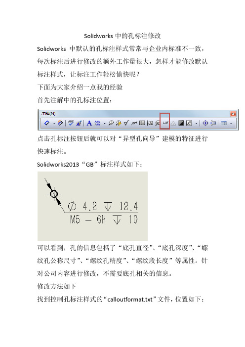
Solidworks中的孔标注修改
Solidworks中默认的孔标注样式常常与企业内标准不一致,
每次标注后进行修改的额外工作量很大,怎样才能修改默认
标注样式,让标注工作轻松愉快呢?
下面为大家介绍一点我的经验
首先注解中的孔标注位置:
点击孔标注按钮后就可以对“异型孔向导”建模的特征进行
快速标注。
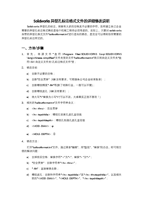
Solidworks2013“GB”标注样式如下:
可以看到,孔的信息包括了“底孔直径”、“底孔深度”、“螺
纹孔公称尺寸”、“螺纹孔精度”、“螺纹段长度”等属性。
针
对公司内容进行修改,不需要底孔相关的信息。
修改方法如下
找到控制孔标注样式的“calloutformat.txt”文件,位置如下:
在:选项\系统选项\文件位置\孔标注格式文件,查看本机的孔标注格式文件位置,如“C:\Program Files\SolidWorks Corp\SolidWorks\lang\chinese‐simplified”在文件夹中找到“calloutformat.txt”文件进行修改,
针对“calloutformat.txt”文件中GB段的内容进行修改:
txt中各文件的意义如下:
*以上 = 右边的每个字符串可以自定义来符合普通文字条目
*或合适的异形孔向导变量。
一个变量可替代另一变量使用。
*异形孔向导变量为小写字母,形式为: <hw‐type>
*大写字母项目为 SolidWorks 符号名称,形式为: <MOD‐DIA>
*
*以上 = 左边的新条目将不被使用。
*删除以上 = 左边的任何条目可能会引起相关的孔具有空白孔标注。
*
*有效的异形孔向导变量如下:
*VARIABLE DESCRIPTION*
*<hw‐type> Type
*<hw‐std> Standard
*<hw‐fsttyp> Fastener Type
*<hw‐fstsze> Fastener Size
*
*<hw‐cbdepth> Counterbore Depth
*<hw‐cbdia> Counterbore Diameter
*<hw‐cdrlang> Counterdrill Angle
*<hw‐cdrldepth> Counterdrill Depth
*<hw‐cdrldia> Counterdrill Diameter
*<hw‐csang> Countersink Angle
*<hw‐csdia> Countersink Diameter
*<hw‐depth> Depth
*<hw‐diam> Diameter
*<hw‐drlang> Drill Angle
*<hw‐endcond> End Condition
*<hw‐fscsang> Far Side Countersink Angle
*<hw‐fscsdia> Far Side Countersink Diameter
*<hw‐headclr> Head Clearance
*<hw‐holedia> Hole Diameter
*<hw‐holedepth> Hole Depth
*<hw‐mjrdia> Major Diameter
*<hw‐midcsang> Middle Countersink Angle
*<hw‐midcsdia> Middle Countersink Diameter
*<hw‐minordia> Minor Diameter
*<hw‐nscsang> Near Side Countersink Angle
*<hw‐nscsdia> Near Side Countersink Diameter
*<hw‐tapdrldepth> Tap Drill Depth
*<hw‐tapdrldia> Tap Drill Diameter
*<hw‐threadang> Thread Angle
*<hw‐threaddepth> Thread Depth
*<hw‐threaddesc> Thread Description
*<hw‐threaddia> Thread Diameter
*<hw‐threadclass> Thread Class (1B, 2B or 3B, applies to Ansi Inch holes only) *<hw‐threadseries> Thread Series
*<hw‐threadsize> Thread Size
*<hw‐thruholedepth> Thru Hole Depth
*<hw‐thruholedia> Thru Hole Diameter
*<hw‐thrutapdrldp> Thru Tap Drill Depth
*<hw‐thrutapdrldia> Thru Tap Drill Diameter
*<hw‐descrp> Description
* Cosmetic thread callout variables
*<cthrd‐std> Standard
*<cthrd‐type> Type
*<cthrd‐size> Size
*<cthrd‐major‐dia> Major Diameter
*<cthrd‐minor‐dia> Minor Diameter
*<cthrd‐depth> Thread Depth
针对TAPPED HOLES字段即螺纹孔字段进行修改
调整前:
TAP‐BLIND=<MOD‐DIAM> <hw‐tapdrldia> <HOLE‐DEPTH>
<hw‐tapdrldepth>;\
<hw‐threaddesc> <hw‐threadclass> <HOLE‐DEPTH> <hw‐threaddepth>
调整后:
TAP‐BLIND=<hw‐threaddesc>深<hw‐threaddepth>
调整后标注样式如下:
希望对大家有帮助。