BELIMO风门执行器
风门执行器

快速风门执行器
系列
旧型号
LMQ.. LMQU24
LMQU24-SR
NMQ.. NMQU24
NMQU24-SR
新型号 LMQ24A LMQ24A-SR NMQ24A NMQ24A-SR
机械式自复位风门执行器
系列
旧型号
新型号
NFA.. NFU
NFA
NFU-S2
NFA-S2
NFU24-SR
NF24A-SR
开关型最大50dB(A) 调节型及三态型最大35dB(A)
开关型最大50dB(A) 调节型及三态型最大30dB(A)
62dB(A)
电缆 1m
L/R安装选择
最大95°,可通过机械限位装置调节
机械指示器
IP42
IP54
CE 遵循 2004/108/EC
CE 遵循 2006/95/EC
-30...+50°C
16
NFA
55
17
NFA-S2
56
18
NF24A-SR
57
19
机械式自复位风门执行器, 20Nm
20
SFA
58
SFA-S2
59
21
SF24A-SR
60
22
机械式自复位风门执行器, 30Nm
23
EF24A-S2
61
24
EF24A-SR
62
25
EF230A-S2
63
26
电子式自复位风门执行器, 40Nm
LF230-S
LF24-3
TF24-SR
LF24-SR
开关型75s;调节型 / 三态型 150s 25s @ -20...+50°C / 最大60s @ -30°C
Belimo NM230A 调节器说明书

T2-NM230A • en • v2.2 • 04.2009 • Subject to changes1 / 2NM230ADamper actuator for adjusting air dampers in ventilation and air-conditioning systems for building services installations • For air dampers up to approx. 2 m 2• Torque 10 Nm• Nominal voltage AC 100 ... 240 V • Control: Open-close or 3-pointTechnical dataElectrical dataNominal voltageAC 100 ... 240 V, 50/60 Hz Nominal voltage rangeAC 85 ... 265 VPower consumption In operationAt restFor wire sizing2.5 W @ nominal torque 0.6 W 5.5 VAConnectionCable 1 m, 3 x 0.75 mm 2Functional dataTorque (nominal torque)Min. 10 Nm @ nominal voltage Manual override Gearing latch disengaged with pushbutton, can be locked Angle of rotation Max. 95°, can be limited at both ends with adjustable mechanical end stops Running time150 s / 90°Sound power level Max. 35 dB (A)Position indicationMechanical, pluggableSafetyProtection class II Totally insulatedDegree of protection IP54 in any mounting position NEMA 2, UL Enclosure Type 2EMCLow voltage directive CE according to 2004/108/EC CE according to 2006/95/ECCertificationcULus according to UL 60730-1A and UL 60730-2-14and CAN/CSA E60730-1:02Certified to IEC/EN 60730-1 and IEC/EN 60730-2-14Mode of operation Type 1Rated impulse voltage 2.5 kV Control pollution degree 3Ambient temperature range –30 ... +50°C Non-operating temperature –40 ... +80°CAmbient humidity range 95% r.H., non-condensating MaintenanceMaintenance-freeDimensions / WeightDimensions See «Dimensions» on page 2WeightApprox. 750 gSafety notes!• The actuator is not allowed to be used outside the specified field of applica t ion, especially in aircraft or any other form of air transport.• Caution: Power supply voltage!• Assembly must be carried out by trained personnel. Any legal regulations or regulations issued by authorities must be observed during assembly.• The device may only be opened at the manufacturer‘s site. It does not contain any parts that can be replaced or repaired by the user.• The cable must not be removed from the device.• When calculating the required torque, the specifications supplied by the damper manufacturers (cross section, design, installation site), and the air flow conditions must be observed.• The device contains electrical and electronic components and is not allowed to be disposed of as household refuse. All locally valid regulations and requirements must be observed......................................Damper actuator, AC 100 ... 240 V, 10 Nm2 / 2T2-NM230A • en • v2.2 • 04.2009 • Subject to changes AccessoriesDescriptionData sheet Electrical accessories Auxiliary switch S..A..T2 - S..A..Feedback potentiometer P..A..T2 - P..A..Mechanical accessoriesVarious accessories (clamps, shaft extensions etc.)T2 - Z-NM..A..Product featuresSimple direct mountingSimple direct mounting on the damper spindle with a universal spindle clamp, supplied with an anti-rotation strap to prevent the actuator from rotating.Manual overrideManual override with push-button possible (the gear is disengaged for as long as the button is pressed or remains locked).Adjustable angle of rotation Adjustable angle of rotation with mechanical end stops.High functional reliabilityThe actuator is overload-proof, requires no limit switches and automatically stops when the end stop is reached.Electrical installationWiring diagramsOpen-close control 3-point control Direction of rotationCable colours:1 = blue 2 = brown 3 = whiteNotes• Caution: Power supply voltage!• Other actuators can be connected in parallel.Please note the performance data.!Dimensions [mm]Dimensional drawings* Option (Accessory K-NA).....................................。
BIFFI电动执行器
November/11/2004
BIFFI ITALIA srl
19
PremiTork/F02
与阀门安装法兰
November/11/2004
BIFFI ITALIA srl
20
PremiTork/F02
阀门轴套尺寸
November/11/2004
BIFFI ITALIA srl
21
PremiTork/F02
10双方向机械限位biffiitaliasrl20premitorkf02与阀门安装法兰biffiitaliasrl21premitorkf02阀门轴套尺寸biffiitaliasrl22premitorkf02l无需离合切换l电动操作时不旋转l手轮操作l操作力符合规范手轮biffiitaliasrl23premitorkf02l低于30c时自动加热l功率10wattsl内部控制单元供电防凝加热器biffiitaliasrl24premitorkf02l标准窗式位于外壳顶部l可选beacon式就地指示器biffiitaliasrl25premitorkf02l无触点绝对位置传感器110角度范围内可设定l根据电机特性进行双向扭矩检测l40到100公称扭矩可调可用旋转开关分10级调整l行程时间可用旋转开关分10步调整l温控开关可限制执行机构内部温度电机控制系统内部检测元件biffiitaliasrl26premitorkf02l执行机构换向控制l内部或外部供电24vdcvac的远方控制l远方控制可选外部供电120vdcvaclpushtorun点动3线远方控制opclcl4spstnonc保持式开关用于全开和全关位置的远传指示l输出触点容量
设计理念:
l 标准型执行机构 l 3种外壳,6 个规格,扭矩从 63 to 2000 Nm l 电源 24 到 240 VDC 或 VAC/1Ph (50/60Hz), 任意。 l 10 级可调开关时间,范围 8 到 90 秒
SCHIEBEL电动执行器技术参数表说明书

TREIBENDE KRAFT FAILSAFE - ACTUSAFETechnical data sheet- PowerFlue gas treatmentHydro power plants Biomass power plants Nuclear power plants Boiler construction- Oil and GasReGas storagesTPower Plant Nueva CTE Habanaend user:Santa Cruz del NorteCubaSchiebel actuators in use:120 pcsCogeneration plant Salzburg RVL Lenzing - waste industryWORKING PRINCIPLEIn normal operation, the electromagnetic clutch is activated and couples the actuator and the failsafe unit. The movement of the actuator is transferred to the output of the failsafe unit, so the fi nal control element is oper-ated according to the position of the actuator.In case of power failure or releasing the ESD command via a cable or bus, the electromagnetic clutch opens and separates the self-locking actuator from the failsafe unit. Now the preloaded spring package is able to Ball screw spindle Spindle nutMultiturn actuatorDisc spring packageHydraulic damper DIMENSIONAL DRAWINGS WIRING DIAGRAMSStandard linear actuator controlled ACTUSAFE unit Assembling consoleControl Eddy current brakeDisc brake package switchSpindle nut Eddy current brakeBall screw spindleDisc brake package Parking brakeSpindle nuthand wheel engaged hand wheel disengagedIn normal operation, the electromagnetic clutch is activated and couples the actuator and the failsafe unit. The movement of the actuator is transferred to the output of the failsafe unit, so the fi nal control element is operated according to the position of the actuator.In case of power failure or releasing the ESD command via a cable or bus, the electromagnetic clutch opens and separates the self-locking actuator from the failsafe unit. Now the preloaded spring package is able to release, by moving the output unit with the fi nal control element into the failsafe position.The speed of this movement (failsafe speed) is limited by a maintenance free eddy current brake.The position of the fi nal control element is permanently monitored with the position sensing, so no start-up procedure is necessary for the failsafe unit to be re-armed.In case of activating the manual override a failsafe operation will be triggered by opening the electromagnetic clutch. After completion of the the move-ment, the fi nal control element can be moved in every position by the hand wheel.To deactivate the manual override the fi nal control element must be moved back into the failsafe position by the hand-wheel and the override must beMultiturn actuatorrackpinionDisc spring packageSpindle nutBall screw spindle Pinion reducer Eddy current brake Parking brakeThree phase AC motor DIMENSIONAL DRAWINGS WIRING DIAGRAMSSCHIEBELAntriebstechnik Ges.m.b.H.Josef-Benc-Gasse 41230 Vienna, AustriaT: +43 (0)1 66 108-0F: +43 (0)1 66 108-4*****************/actuators Niederlassungen / Branches : ■ Vertriebspartner / Sales partners:。
伯纳德电动执行器产品资料
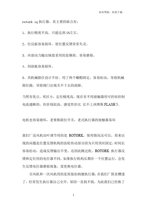
rotork iq执行器,其主要的缺点有:1。
执行精度不高,只能达到1%左右。
2。
位反板容易损坏。
使位置反馈常常失灵。
3。
内部动力输出轴套采用的是铜质,容易磨损。
4。
伺放板容易损坏。
5。
其机械限位设计不好,用了两个螺帽固定,容易松动,导致机械限位跑,导致阀门出现关不下去的故障。
当然有优点,死区小,定位精度高,现在有不用接触器用可控硅控制电流通断的,但价钱较高,感觉性价比比不上西博斯FLASH 5。
电机也容易烧坏,老要换限位开关,老式执行器的接触器易坏我们厂送风机动叶调节用的是ROTORK,使用情况还可以,原来出现的问题是位置反馈机构的齿轮传动部分因为只用顶丝固定,时间长容易松动,造成反馈输出不变,还因此跳过机。
ROTORK执行器反馈和定位用的电位器不同,如果执行机构长期在一个位置运行,会发生反馈电位器磨损现象,需更换电位器。
引风机和一次风机用的是原装伯纳德执行器,在我们厂简直糟透了,经常发生执行器自己全开,原因一直找不找,为此我们已经换了十几块定位板了,每次换完板子可以稳定几个月,每块板子价格大概3000元,备品有好几台。
另外,反馈电位器也经常坏。
最近我们正在考虑换型,所以在调研AUMA和SIPOS。
AUMA我们厂用在磨煤机冷、热风调门上,环境温度较高,出现过好几次电机烧坏现象,交流接触器,电源板也容易出问题,调整起来还是比较方便的,但是内部板件太多,共有5块,价格也比较贵,最贵的板子定位板一块将近10000元,我觉得AUMA的好处是机械机构比较好,可以说免维护。
在环境不太好的地方最好使用分体安装,这样效果可能好些。
没有使用过的执行器就是SIPOS,希望能为我提供使用信息。
谢谢!ROTORK IQ在我厂应用中出现一倒厂用电既烧保险现象。
伯纳德性能较稳定,但出现过一次电位器不随执行器转动事件。
SIPOS的容易出现死机,重新送电恢复我厂用的最多的是天津七厂的伯纳德执行器,但是板子经常坏。
出现几次不明原因的全开。
BELIMO电动风门执行器,阀门电动执行器
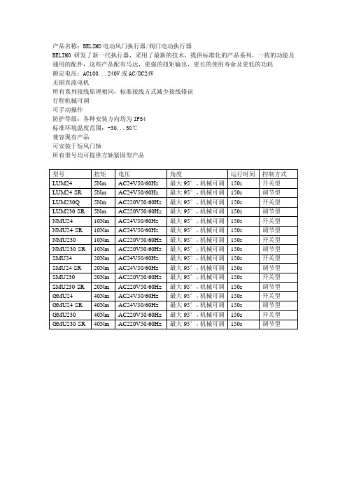
产品名称:BELIMO电动风门执行器/阀门电动执行器BELIMO 研发了新一代执行器,采用了最新的技术,提供标准化的产品系列,一致的功能及通用的配件,这些产品配有马达,更强的扭矩输出,更长的使用寿命及更低的功耗额定电压:AC100...240V或AC/DC24V无刷直流电机所有系列接线原理相同,标准接线方式减少接线错误行程机械可调可手动操作防护等级:各种安装方向均为IP54标准环境温度范围:-30...50℃兼容现有产品可安装于短风门轴所有型号均可提供方轴紧固型产品型号扭矩电压角度运行时间控制方式LUM24 5Nm AC24V50/60Hz 最大95°,机械可调150s 开关型LUM24-SR 5Nm AC24V50/60Hz 最大95°,机械可调150s 调节型LUM230Q 5Nm AC220V50/60Hz 最大95°,机械可调150s 开关型LUM230-SR 5Nm AC220V50/60Hz 最大95°,机械可调150s 调节型NMU24 10Nm AC24V50/60Hz 最大95°,机械可调150s 开关型NMU24-SR 10Nm AC24V50/60Hz 最大95°,机械可调150s 调节型NMU230 10Nm AC220V50/60Hz 最大95°,机械可调150s 开关型NMU230-SR 10Nm AC220V50/60Hz 最大95°,机械可调150s 调节型SMU24 20Nm AC24V50/60Hz 最大95°,机械可调150s 开关型SMU24-SR 20Nm AC24V50/60Hz 最大95°,机械可调150s 调节型SMU230 20Nm AC220V50/60Hz 最大95°,机械可调150s 开关型SMU230-SR 20Nm AC220V50/60Hz 最大95°,机械可调150s 调节型GMU24 40Nm AC24V50/60Hz 最大95°,机械可调150s 开关型GMU24-SR 40Nm AC24V50/60Hz 最大95°,机械可调150s 调节型GMU230 40Nm AC220V50/60Hz 最大95°,机械可调150s 开关型GMU230-SR 40Nm AC220V50/60Hz 最大95°,机械可调150s 调节型。
Belimo NKQX24-SR 可定制的失效安全调节阀门驱动器说明书
NKQX24-SRCustomizable Fail-Safe modulating actuatorfor controlling dampers in typical commercial HVAC applications.• Torque motor 54 in-lb [6 Nm]• Nominal voltage AC/DC 24 V • Control Modulating• Position feedback 2...10 VTechnical dataElectrical dataNominal voltageAC/DC 24 V Nominal voltage frequency 50/60 HzNominal voltage rangeAC 19.2...28.8 V / DC 21.6...28.8 V Power consumption in operation 11 W Power consumption in rest position 3 W Transformer sizing 22 VAElectrical Connection18 GA appliance or plenum cables, 1 m, 3 m or 5 m, with or without 1/2" NPT conduit connectorOverload Protection electronic throughout 0...95° rotation Electrical Protectionactuators are double insulated Functional dataTorque motor 54 in-lb [6 Nm]Operating range Y 2...10 VOperating range Y note 4...20 mA w/ ZG-R01 (500 Ω, 1/4 W resistor)Input impedance 100 kΩ for 2...10 V (0.1 mA), 500 Ω for 4...20 mA Position feedback U 2...10 V Position feedback U note Max. 0.5 mASetting Fail-Safe Position adjustable with dial 0...100% in 10% increments Bridging time (PF)0 s Pre-charging time 9...15 sDirection of motion motor selectable with switch 0/1Direction of motion fail-safe reversible with switch Manual override external push button Angle of rotation Max. 95°Angle of rotation note adjustable with mechanical stop Running Time (Motor)4 s / 90°Running time motor variable 4...10 s Running time fail-safe <4 s Noise level, motor 60 dB(A)Noise level, fail-safe 60 dB(A)Position indicationMechanical, 30...65 mm stroke Safety dataPower source ULClass 2 Supply Degree of protection IEC/EN IP54Degree of protection NEMA/UL NEMA 2Enclosure UL Enclosure Type 2Agency Listing cULus acc. to UL60730-1A/-2-14, CAN/CSA E60730-1:02, CE acc. to 2014/30/EU Quality StandardISO 9001NKQX24-SRFootnotesApplicationOperationTypical specificationSafety dataUL 2043 CompliantSuitable for use in air plenums per Section 300.22(C) of the NEC and Section 602 of the IMCAmbient humidity Max. 95% RH, non-condensing Ambient temperature -22...122°F [-30...50°C]Storage temperature -40...176°F [-40...80°C]Servicingmaintenance-free Weight Weight2.4 lb [1.1 kg]MaterialsHousing material UL94-5VA†Rated Impulse Voltage 800V, Type of action 1.AA, Control Pollution Degree 3Product featuresFor fail-safe, modulating control of dampers in HVAC systems. Actuator sizing should be done in accordance with the damper manufacturer’s specifications. The actuator is mounted directly to a damper shaft up to 1.05” in diameter by means of its universal clamp. A crank arm and several mounting brackets are available for applications where the actuator cannot be direct coupled to the damper shaft. The actuator operates in response to a 2 to 10 VDC or, with the addition of a 500Ω resistor, a 4 to 20 mA control input from an electronic controller or positioner. A 2 to 10 VDC feedback signal is provided for position indication. Not to be used for a master-slave application.The NKQ..24-SR actuator provides 95° of rotation and a visual indicator shows the position of the actuator. When reaching the damper or actuator end position the actuator automatically stops. The gear can be manually disengaged by pressing the black button located on theactuator cover. The NKQ..24-SR actuators use a brushless DC motor, which is controlled by an Application Specific Integrated Circuit (ASIC). The ASIC monitors and controls the actuators rotation and provides a digital rotation sensing (DRS) function to prevent damage to theactuator in a stall condition. Power consumption is reduced in a holding mode. The actuator is electronically protected against overload. The anti-rotation strap supplied with the actuator will prevent lateral movement. Add-on auxiliary switches or feedback potentiometers are easily fastened directly onto the actuator body for signaling and switching functions.Fail-Safe IndicationLED status indicator lights sequence:Yellow off / Green on: operation ok, no faultsYellow off / Green blinking: fail-safe mechanism is active Yellow on / Green off: fault is detectedYellow off / Green off: not in operation / capacitors charging Yellow on / Green on: adaption runningModulating control, electrical fail-safe damper actuators shall be electronic direct-coupled type, which require no crank arm and linkage and be capable of direct mounting to shaft up to 1.05" diameter. Actuators must provide modulating damper control response to a 2 to 10 VDC or, with the addition of a 500 Ω resistor, a 4 to 20 mA control input from an electronic controller orpositioner. Actuators shall have brushless DC motor technology and be protected from overload at all angles of rotation. Actuators shall have reversing switch and manual override on the cover. Run time shall be constant and independent of torque. A 2 to 10 VDC feedback signal shall be provided for position feedback. Actuators shall be cULus listed, have a 5-year warranty, and be manufactured under ISO 9001 International Quality Control Standards. Actuators shall be as manufactured by Belimo.NKQX24-SR AccessoriesElectrical accessories Description TypeDC Voltage Input Rescaling Module IRM-100Feedback potentiometer 10 kΩ add-on, grey P10000A GRFeedback potentiometer 1 kΩ add-on, grey P1000A GRFeedback potentiometer 140 Ω add-on, grey P140A GRFeedback potentiometer 2.8 kΩ add-on, grey P2800A GRAuxiliary switch, mercury-free P475Auxiliary switch, mercury-free P475-1Feedback potentiometer 5 kΩ add-on, grey P5000A GRFeedback potentiometer 500 Ω add-on, grey P500A GRPTA-250Convert Pulse Width Modulated Signal to a 2...10 V Signal for BelimoProportional ActuatorsAuxiliary switch 1x SPDT add-on S1AAuxiliary switch 2x SPDT add-on S2APositioner for wall mounting SGA24Positioner for front-panel mounting SGF24Cable conduit connector 1/2"TF-CC USResistor, 500 Ω, 1/4" wire resistor with 6" pigtail wires ZG-R01Resistor kit, 50% voltage divider ZG-R02Transformer, AC 120 V to AC 24 V, 40 VA ZG-X40Adapter for auxiliary switch and feedback potentiometer Z-SPA Mechanical accessories Description TypeActuator arm for standard shaft clamp (one-sided)AH-25Shaft extension 170 mm ø10 mm for damper shaft ø6...16 mm AV6-20Shaft extension 240 mm ø20 mm for damper shaft ø8...22.7 mm AV8-25Clamp NM/AM 1/2", 3/4", 1"K-AM25Ball joint suitable for damper crank arm KH8KG8Damper crank arm Slot width 8.2 mm, for ø1.05"KH12Damper crank arm Slot width 6.2 mm, clamping range ø10...18 mm KH6Damper crank arm Slot width 8.2 mm, clamping range ø10...18 mm KH8Shaft clamp reversible, clamping range ø10...20 mm K-SAPush rod for KG6 & KG8 ball joints (36” L, 5/16” diameter).SH8Anti-rotation bracket TF/NKQ/AM/NM/LM.TF-PWrench 0.32 in and 0.39 in [8 mm and 10 mm]TOOL-06Mounting bracket for AF..ZG-100Mounting bracket ZG-101Mounting bracket ZG-103Mounting bracket ZG-104Damper clip for damper blade, 3.5” width.ZG-DC1Damper clip for damper blade, 6” width.ZG-DC21" diameter jackshaft adaptor (11" L).ZG-JSA-11-5/16" diameter jackshaft adaptor (12" L).ZG-JSA-21.05" diameter jackshaft adaptor (12" L).ZG-JSA-3Mounting kit for linkage operation for flat installation ZG-NMAShaft extension for 1/2" diameter shafts (3.8" L).ZG-NMSA-1Weather shield 13x8x6" [330x203x152 mm] (LxWxH)ZS-100Baseplate, for ZS-100ZS-101Weather shield 406x213x102 mm [16x8-3/8x4"] (LxWxH)ZS-150Jackshaft mounting bracket.ZG-120Tools Description TypeBelimo PC-Tool, Software for adjustments and diagnostics MFT-PSignal simulator, Power supply AC 120 V PS-100 Electrical installationWarning! Live electrical components!During installation, testing, servicing and troubleshooting of this product, it may be necessaryto work with live electrical components. Have a qualified licensed electrician or other individualwho has been properly trained in handling live electrical components perform these tasks.Failure to follow all electrical safety precautions when exposed to live electrical componentscould result in death or serious injury.NKQX24-SRMeets cULus requirements without the need of an electrical ground connection.Provide overload protection and disconnect as required.Actuators may also be powered by DC 24 V.Only connect common to negative (-) leg of control circuits.A 500 Ω resistor (ZG-R01) converts the 4...20 mA control signal to 2...10 V.Actuators may be connected in parallel if not mechanically linked. Power consumption andinput impedance must be observed.2...10 V / 4...20 mA ControlDimensions。
执行器讲座幻灯片
DKJ-W户外型角行程电动执行机构
•
DKJ-W户外型角行程电动执行机构 用途 DKJ-W型电动执行器是DDZ型电动单元组合仪表中的一个执行单元。它 接受变送,调节等单元的信号或操作单元的手控信号,自动的调节机构,完 成调节任务。广泛用于电站、化工、冶金、矿山、轻工业等自动话控制系统 中。 1、 户外型产品采用“0”型结构设计及较高的绝缘处理,其防护等级为 IP65。 2、 位置发送器全部采用圆筒结构模块化电流变送器,产品具有结构简 单可靠性高等特点。 3、 终端具备电限位开关调整方便。 主要技术指标(与DFC伺服放大器配合) 1、 输入信号:Ⅲ:4-20 mA DC或Ⅱ:0-10 mA DC 2、 输入通道:三个 3、 输入通道电阻:Ⅲ型250Ω Ⅱ型200Ω 4、基本误差限:±2.5% 5、回差:≤1.5% 6、死区:≤3 % 7、阻尼特性:≤3次半周期 8、电源:单相电压 ,频率50Hz 9、使用环境温度:-10 —— +55℃或-25 —— +70℃ 10、防护等级:IP65
• •
德瑞(EMG-DREMHO) (2)
易艾姆(EIM) (1)
• • ----美国EIM公司 EIM2000系列电动执行机构
p1
γ
+
υ1 2
2g
=
p2
γ
+
υ22
2g
+ hj
p1 υ p2 υ2 z1+ + = z2 + + + hj .......... .......... .......... 2) ...( γ 2g γ 2g
1.工作原理
• 位置信号变换电路将反映执行机构位 置的1000欧三线滑线电阻信号的变化情况 转为4-20mA。控制输入与位置信号同时送 到偏差放大器进行比较,比较结果控制固 态开关的通断,实现对执行机构的开或关 控制。根据控制要求调整灵敏度,可以改 变跟踪精度和消除因机械惯性可能产生的 振荡。
Belimo 空气控制系统技术文档说明书
T e c h .D o c - 01/20 - S u b j e c t t o c h a n g e . © B e l i m o A i r c o n t r o l s (U S A ), I n c .Input/Output SpecificationsType Name Description Electrical Specifi cation Input RSupply HotAC 24 V, ± 20%, 50/60HzInputG/OCCFan Signal (occupied)On/Off, AC 24 V, ± 20%, 50/60Hz Input C Supply Common CommonInput Y1Cooling requirement Stage 1On/Off, AC 24 V, ± 20%, 50/60Hz Input Y2Cooling requirementStage 2On/Off, AC 24 V, ± 20%, 50/60Hz Input W1/O/B Heating requirement Stage 1On/Off, AC 24 V, ± 20%, 50/60Hz Input SAT ±Supply Air TemperatureSensorType: 10K NTC (Type II thermistor)Input OAT ±Outdoor Air Temperature Type: 10K NTC (Type II thermistor)InputOAH ±Outdoor Air HumidityDC 0...10 VAuto Detection: Sensor present if voltage 0.5...10 VInput RAT ±Return Air Temperature Type: 10K NTC (Type II thermistor)Input RAH ±Return Air Humidity DC 0...10 VAuto Detection: Sensor present if voltage 0.5 (10V)Output CC1Compressor 1RTU Stage 1Mechanical Cooling Circuitry 100'000 cycles @ inrush currentof 3A, normal current 1.5A Impedance for Auto detection @ 24 V:<60O Ω @ 60Hz <80O Ω @ 50HzOutputCC2Compressor 2RTU Stage 2Mechanical CoolingCircuitry100'000 cycles @ inrush currentof 3A, normal current 1.5A Impedance for Auto detection @ 24 V:<60O Ω @ 60Hz <80O Ω @ 50HzOutput Act 1Actuator supply common Common Output Act 2Actuator supply hot AC 24 V, 50/60Hz Output Act 3Actuator control output DC 2...10 V Input Act 5Actuator feedback signalDC 2...10 VInstallationYou can mount the ZIP Economizer in any orientation; it is recommended that you mount it in a position that will allow full utilization of the LCD and key pad and proper clearance for installation, servicing, wiring, and removal.Take the overall dimensions of 6.63" [168.5] x 7.12" [181] x 2" [50.8] and mount in the interior of the RTU in a convenient location that you can access. Secure the ZIP utilizing #8 self-tapping screws (included). A minumum of two tabs need to be secured, one which is a top tab. Ideally secure all four tabs. Wire the electrical connection using ¼” female insulated spade connectors to prevent corrosion.Technical DataPower supplyAC 24 V ± 20%, 50/60 Hz; Class 2 power source Power consumption rating*4 VA base control (ECON-ZIP-BASE)5.5 VA base control with Energy Module (ECON-ZIP-BASE + ECON-ZIP-EM)5 VA base control with Communication Module (ECON-ZIP-BASE + ECON-ZIP-COM)6.5 VA base with Energy Module andCommunication Module. (ECON-ZIP-BASE + ECON-ZIP-EM + ECON-ZIP-COM)Rated impulse voltage 330 VConnectors ¼” male spade connectors Environmental RoHS, conformally coated Software classA Control pollution degree 3Temperature input signal NTC 10k Ω, Type IIHumidity5 to 95% RH non-condensingHumidity input signal DC 0...10 V; corresponds to 0...100%HousingNEMA 1Housing materialUL94-5VAAmbient temperature range -40...+158°F [-40...+70°C]Storage temperature range -40...+176°F [-40...+80°C]Display2x16 character LCD; LED backlight; transflectiveDisplay op. range**-22...+176°F [-30...+80°C]Agency listing cULus acc. to UL873, CAN/CSA C22.2, No. 24-93Energy code compliantASHRAE 90.1, CA Title 24, NECBDimensions (Inches [mm])7.12 [181]2.42 [61.6]0.18 [4.6]6.04 [153.4]5.5 [140]6.63 [168.5]2 [50.8]0.16 [4.1]ECON-ZIP-BASEZIP Economizer™ Base Module* The power consumption is for the control only and does not include connected loads such as actuator, compressors, fans, and sensors. For transfomer sizing, the power consumption of these attached components must be included.** At low temperature the display has decreased response time. Below -22°F [-30°C] it will not function.T e c h .D o c - 01/20 - S u b j e c t t o c h a n g e . © B e l i m o A i r c o n t r o l s (U S A ), I n c .ECON-ZIP-BASEZIP Economizer™ Base Module Wiring DiagramsR CG OCC W1O/B Y1Y2ACT1ACT2ACT3ACT5R C R CG/OCC W1/O/B Y1Y2CC1CC2OAT+OAT-OAH+OAH-SAT+SAT-RAT+RAT-RAH+RAH--SR1 -Common2 + Hot3 Y Input, 2 to 10V 5 U Output, 2 to 10VACT 1ACT 2ACT 3ACT 5R CY1Y2ECON-ZIP-10K Supply Air TempSAT +SAT -OAT + OAT -CC1CC2OCC W1RTU Stage 1 Mechanical CoolingCircuitryRTU Stage 2 Mechanical CoolingCircuitryECON-ZIP-10K Outside Air TempTHERMOSTATRTU TERMINALECON-ZIP-BASE575251535659R CG OCCW1O/B Y1Y2ACT1ACT2ACT3ACT5R C R CG/OCC W1/O/B Y1Y2CC1CC2OAT+OAT-OAH+OAH-SAT+SAT-RAT+RAT-RAH+RAH--SR1 -Common2 + Hot3 Y Input, 2 to 10V 5 U Output, 2 to 10VACT 1ACT 2ACT 3ACT 5R CY1Y2ECON-ZIP-10K Supply Air Temp SAT +SAT -CC1CC2OCC W1RTU Stage 1 Mechanical CoolingCircuitry RTU Stage 2 Mechanical CoolingCircuitryECON-ZIP-TH Outside Air EnthalpyT (+)T (-)24 V (R)RH (+)RH (-)OAT + OAT -OAH + OAH - RECON-ZIP-BASETHERMOSTATRTU TERMINAL57505251535659When the thermostat is not equipped with occupancy control, "Fan On" output "G" shall be wired to the ECON-ZIP-BASE.W1 must be wired for Heat Pump operation if conventional thermostat is used in conjunction with Defrost Board. If Thermostat and RTU use O/B control reversing valve position, O/B must be wired to W1 on ECON-ZIP-BASE.Existing refrigeration safety devices may exist, consult RTU wiring diagram515253If RTU is not a Heat Pump using a conventional thermostat and it is desired to record heating operation hours, connect W1 to ECON-ZIP-BASE.56Actuators can be mounted in parallel with the ACT3 output from the ZIP Economizer. The ACT5 feedback input should be wired to the Outside Air damper actuator feedback wire.57Iso relay may be required with certain RTU manufacturers.59Power source should be the same as ECON-ZIP-BASE.50When the thermostat is not equipped with occupancy control, "Fan On" output "G" shall be wired to the ECON-ZIP-BASE.Existing refrigeration safety devices may exist, consult RTU wiring diagram5153If RTU is not a Heat Pump using a conventional thermostat and it is desired to record heating operation hours, connect W1 to ECON-ZIP-BASE.56W1 must be wired for Heat Pump operation if conventional thermostat is used in conjunction with Defrost Board. If Thermostat and RTU use O/B control reversing valve position, O/B must be wired to W1 on ECON-ZIP-BASE.52Actuators can be mounted in parallel with the ACT3 output from the ZIP Economizer. The ACT5 feedback input should be wired to the Outside Air damper actuator feedback wire.57Thermostat with two (2) stages of cooling required. Thermostats with mercury switches are not compatible with the ZIP Economizer.58Iso relay may be required with certain RTU manufacturers.59T e c h .D o c - 01/20 - S u b j e c t t o c h a n g e . © B e l i m o A i r c o n t r o l s (U S A ), I n c .R CG/OCCW1/O/BY1Y2ACT1ACT2ACT3ACT5R C R CG/OCC W1/O/B Y1Y2CC1CC2OAT+OAT-OAH+OAH-SAT+SAT-RAT+RAT-RAH+RAH--SR1 -Common2 + Hot3 Y Input, 2 to 10V 5 U Output, 2 to 10VACT 1ACT 2ACT 3ACT 5R CY1Y2ECON-ZIP-10K Supply Air Temp SAT +SAT -OAT + OAT -CC1CC2G/OCC W1/O/BRTU Stage 1 Mechanical CoolingCircuitry RTU Stage 2 Mechanical CoolingCircuitryECON-ZIP-TH Outside Air EnthalpyECON-ZIP-THRAT+T (+)T (-)24 V (R)RH (+)RH (-)RAT-RAH+RAH-RT (+)T (-)24 V (R)RH (+)RH (-)OAH + OAH - RECON-ZIP-BASETHERMOSTATRTU TERMINAL5859R CG/OCC W1/O/BY1Y2ACT1ACT2ACT3ACT5R C R CG/OCC W1/O/B Y1Y2CC1CC2OAT+OAT-OAH+OAH-SAT+SAT-RAT+RAT-RAH+RAH--SR1 -Common2 + Hot3 Y Input, 2 to 10V 5 U Output, 2 to 10VACT 1ACT 2ACT 3ACT 5R CY1Y2ECON-ZIP-10K Supply Air TempSAT +SAT -OAT + OAT -THERMOSTATRTU TERMINALCC1CC2G/OCC W1/O/BRTU Stage 1 Mechanical CoolingCircuitry RTU Stage 2 Mechanical CoolingCircuitryECON-ZIP-10K Outside Air TempECON-ZIP-10K Return Air TempRAT+ECON-ZIP-BASE57RAT-59Power source should be the same as ECON-ZIP-BASE.50When the thermostat is not equipped with occupancy control, "Fan On" output "G" shall be wired to the ECON-ZIP-BASE.Existing refrigeration safety devices may exist, consult RTU wiring diagram5153If RTU is not a Heat Pump using a conventional thermostat and it is desired to record heating operation hours, connect W1 to ECON-ZIP-BASE.56W1 must be wired for Heat Pump operation if conventional thermostat is used in conjunction with Defrost Board. If Thermostat and RTU use O/B control reversing valve position, O/B must be wired to W1 on ECON-ZIP-BASE.52Actuators can be mounted in parallel with the ACT3 output from the ZIP Economizer. The ACT5 feedback input should be wired to the Outside Air damper actuator feedback wire.57Thermostat with two (2) stages of cooling required. Thermostats with mercury switches are not compatible with the ZIP Economizer.58Iso relay may be required with certain RTU manufacturers.59Power source should be the same as ECON-ZIP-BASE.50When the thermostat is not equipped with occupancy control, "Fan On" output "G" shall be wired to the ECON-ZIP-BASE.Existing refrigeration safety devices may exist, consult RTU wiring diagram5153If RTU is not a Heat Pump using a conventional thermostat and it is desired to record heating operation hours, connect W1 to ECON-ZIP-BASE.56W1 must be wired for Heat Pump operation if conventional thermostat is used in conjunction with Defrost Board. If Thermostat and RTU use O/B control reversing valve position, O/B must be wired to W1 on ECON-ZIP-BASE.52Actuators can be mounted in parallel with the ACT3 output from the ZIP Economizer. The ACT5 feedback input should be wired to the Outside Air damper actuator feedback wire.57Thermostat with two (2) stages of cooling required. Thermostats with mercury switches are not compatible with the ZIP Economizer.58Iso relay may be required with certain RTU manufacturers.59ECON-ZIP-BASEZIP Economizer™ Base Module Wiring DiagramsT e c h .D o c - 01/20 - S u b j e c t t o c h a n g e . © B e l i m o A i r c o n t r o l s (U S A ), I n c .ZIP EconomizerQuick SetupMoves up through the menu on the same level. Will increase values by one increment at a time. When setting values holding key down willfast scrollMoves down through the menu on the same level. Will decrease values by one increment at a time. When setting values holding key down will fast scroll. Enter sub menu level. Start editing a setting. Store an entered value. esc Escape sub menu tonext higher level.Cancel current actions.iShow additional information on thecurrent menu Itemwhen “i” appears inlower right of display.Moves down through the menu on the same level.Will decrease values by one increment at a time. When setting values holding key down will fast scroll.Enter sub menu level.Start editing a setting. Store an entered value. esc Escape sub menu to next higher level.Cancel current actions.iShow additional information on the current menu Item when “i” appears in lower right of display.Functions1. “Monitor Live Conditions” is used to display settings and live values.2. “Settings” is used to parameterize the ZIP Economizer. (Note: Devices 1 is for CC1, CC2, EF, IF; Devices 2 is for OAH, RAH)3. “Present Devices” is used to verify that the ZIP Economizer's Auto Detected connections are terminated properly. If connected device is not shown, verify wiring. If wiring has continuity and device is verifi ed operational re-enter “Settings” and enable missing device by changing from “Auto” to “Available” or “Installed”.4. “Alarms” is used to view current and historical alarms and delete inadvertently caused alarms.5. “Service and Commissioning” submenu is used to operate the RTU in “Manual Mode” or to perform “Acceptance Test”. “Settings” must to be completed to access.6. “Status” is a display of the current operating mode. It can beaccessed by pressing ”esc”. The action of pressing any key will drop the user down from Status to the next level, so repeatedly pressing “esc” will toggle the display between Status and Monitor Live Conditions. (Note: If status “Setup incomplete” is displayed the RTU cooling operation will be disabled and additional parameters must be set to achieve “Setup complete”.)1. Shut off power to RTU before beginning installation.2. Note orientation, opening rotation, and spring return rotation of damper assembly. Mount Actuator to Outside Air and Return Damper assembly. To ensure tight outside air shutoff; while tightening actuator clamp push damper closed.3. Terminate required Inputs and Outputs(I/O): For the ZIPEconomizer to function correctly, the following I/O, at a minimum, are required to be terminated, wired, and functioning (R, C, Y1, Y2, G, CC1, OAT, SAT, ACT1, ACT2, ACT3, ACT5). See wiring diagrams.4. Sensor confi guation: The ZIP Economizer automatically detects sensors attached and automatically confi gures for single dry bulb, single enthalpy, differential dry bulb and differential enthalpy.“Settings” is the menu displayed when the ZIP Economizer is fi rstpowered. Press “OK” to parameterize required settings. Reference above Keypad Key defi nition instructions and navigate as needed.WARNING Live Electrical Components!During installation, testing, servicing and troubleshooting of this product, it may be necessary to work with live electrical components. H ave a qualifi ed licensed electrician or other individual who has been properly trained in handling live electrical components perform these t asks. Failure to follow all electrical safety precautions when exposed to live electrical components could result in death or serious injury.T e c h .D o c - 01/20 - S u b j e c t t o c h a n g e . © B e l i m o A i r c o n t r o l s (U S A ), I n c .1. ZIP Code US or Canada (sets the free cooling changeover high limit and temperature units F/C)a. When the Zip Code submenu is displayed enter “OK” to begin “US” Zip Code parameterization. If “Canada” Postal Code is desired press the up/down arrow to access.i. Press OK to access digit 1 (flashing) then use the up/down arrow to parameterize; enter OK when complete. Repeat until all digits are complete. If a mistake is made press “esc” andrepeat from beginning.ii. When all Zip Code or Postal Code digits are entered press “esc” to move up a level then press the up/down arrow to access next settings parameter.2. Vent Min Pos (Outdoor Air Damper Ventilation Minimum Position)a. When the “Vent Min Pos” submenu is displayed press “OK” toparameterize (flashing).b. Use the up/down arrow to parameterize, press “OK” whencomplete. The actuator will immediately drive the damper to the minimum position.3. Additional Parameters may require setting. The ZIP Economizer will auto-detect added Devices such as a CO2 sensor etc. When the ZIP Economizer detects a new device, it will prompt the user in the Status level; navigate to Settings and parameterize blank fi elds. If the devices are connected upon fi rst start up their settings will require parameterization then.4. When all parameters have been set, the ZIP Economizer will show “Setup Complete” if there are still parameters to set, there will be no action. You can verify by pushing esc until status level is reached and it will display “Setup Incomplete”. If this is the case, re-enter settings menu and use up down arrows to fi nd the parameter with blank fi elds and parameterize as described above. Note: you may enter parameters in any order - eg: Vent min Pos before ZIP Code - If the RTU is a heat pump or uses a 2 speed indoor fan, these paramaters should be enabled fi rst, otherwise the logic may go to Setup Complete prematurely.The ZIP Economizer has built in commissioning processes found in Acceptance Test.1. Economizer Test. Use “Economizer Test” to verify RTU Integrated Economizer operation. Navigate to the “Service and Commissioning” menu, press “OK”; press the down arrow to access “Acceptance Test”. Press OK again when “Economizer Test” appears. Press “OK” again to confi rm running test. Follow prompts during test. This test will open damper to 100%, enable power exhaust fan (if connected), enable 1st stage of Mechanical Cooling, reverse this process and then drive to Vent Min Position. When used with a Belimo actuator, the actuator will speed up to reduce test time.2. Manual Mode is used to override outputs after entering a “Timeout” duration.3. Damper Scaling. The test will re-scale the control signal range to maximum resolution (0...100%) over the calibrated (reduced) angle. When using a Belimo actuator, the actuator will speed up to reduce test time.Note: Failure to identify obstructions or improper setup of damper assembly may result in an improper scaling and operation of the damper.)Additional testing can be found later in this document.1. When all entries have been completed, the ZIP Economizer will switch to Status display and show “Setup Complete”, and will immediately show a “Damper scaling starts in 10secs” and will countdown to 0 (be aware, at 0 the damper will start to move at high speed ). A message will scroll saying “Damper scaling for better operation if obstruction is present rescale damper in commissioning menu”. (For detailed instructions on this – please see the section “Service and Commissioning” below. This will open damper to 100% (re-scale control signal if needed). (Note: failure to identify obstructions or improper setup of damper assembly may result in an improper scaling and operation of the damper.)Once scaling is complete, a message will appear saying “Damper scaling successful”. The ZIP will then show “maximum at80° = 100%” That message will show maximum rotation of the damper. This process ensures the damper is always operating and displayed from 0...100%.2. Once the message has appeared, the actuator immediately closes the damper and a countdown begins, until the unit starts to operate in Automatic Mode (be aware, when countdown complete, the RTU will respond to thermostat calls which may enable mechanical cooling).ZIP EconomizerQuick Setup。
搏力谋风产品系列手册说明书
Small Devices, Big Impact.小身材 大妙用 ™搏力谋风产品系列端子连接的角行程执行器线缆连接的直行程执行器带自复位功能的执行器不带自复位功能的执行器线缆连接的可参数化设置角行程执行器, 带特殊控制端子连接的可参数化设置直行程执行器不带自复位功能的超快速运行角行程执行器不带自复位功能的超快速运行直行程执行器适用于极端条件的RobustLine NEMA 4X 角行程执行器,适用于室外应用,不带自复位功能/带自复位功能特殊执行器/改造项目用执行器特殊执行器本文档中列出的执行器专门设计用于建筑设备中风阀的开关与调节控制。
本文档中列出的执行器专门设计用于建筑设备中风阀的开关与调节控制。
计算操作风阀所必需的扭矩或推力时,必须考虑风阀制造商提供的有关横截面、结构、安装地点和气流状况的所有数据。
推荐的风阀尺寸为大约值。
或手操器ZTH AP / ZTH EU 或手操器ZTH AP / ZTH EU风阀执行器总览防火排烟风阀执行器(不带自复位功能/带自复位功能)配件概览不带自复位功能的执行器AV6-20AV6-20AV8-25AV8-251 kΩ、2.8 kΩ配件概览带自复位功能的执行器AV6-20AV8-25AV8-25AV8-25执行器的更多版本,请联系当地的搏力谋销售。
执行器上的辅助开关和反馈电位计只能与适配器执行器上的辅助开关和反馈电位计与双向夹持器组合使用(短轴安装时,安装在下方)配件概览不带自复位功能的特殊执行器AV6-20AV6-20AV8-25AV8-25AV12-25-I AV8-25AV8-25AV8-25配件概览不带自复位功能/带自复位功能的特殊执行器AH-GMA AH-GMA AH-GMA AH-GMA仅根据要求进行组合,请联系当地的搏力谋销售。
1 kΩ、2.8 kΩ)-和..24G-MP对于方轴插件,请联系当地的搏力谋销售。
不带自复位功能的风阀执行器线缆连接的角行程执行器CM24-LCM24-RCM24G-LCM24G-RCM230-LCM230-RCM..线缆连接的角行程执行器LM24A NM24A LM24A-S NM24A-S LM230A NM230A LM230A-S NM230A-S GM..ALM..A SM..ANM..A 端子连接的角行程执行器CM..-T..端子连接的角行程执行器LM24A-TP LM24A-S-TP LM230A-TP LM230A-S-TP GM..A-TPLM..A-TP SM..A-TPNM..A-TPCH24-L60.2CH24-L100.2CH230-L60.2线缆连接的直行程执行器LH..A60SH..A-SR200CH..L100EF..A..SF..A..TF..LF..NF..A..带自复位功能的角行程执行器带自复位功能的角行程执行器逆时针旋转 顺时针旋转CM24K-T-L.2CM24K-T-R.2GK24A-1GK24A-SR带自复位功能的风阀执行器带自复位功能的角行程执行器NKQ..A GK..A特殊执行器不带自复位功能的快速运行角行程执行器TMC24A LMC24A TMC24A-S TMC230A LMC230ATMC230A-SLMC..A NMC..A-MP TMC..A SMC..A-MP不带自复位功能的超快速运行角行程执行器LMQ..A SMQ..ANMQ..A SMD..ANMD..A 不带自复位功能的超快速运行直行程执行器LHQ..A SHQ..ALMQ24A NMQ24A适用于极端条件的RobustLine角行程执行器,不带自复位功能/带自复位功能SM..P NKQ..PNM..PIP 66/67,NEMA 4X – 角行程执行器,适用于室外应用不带自复位功能/带自复位功能SMQ..G NF..G SF..GGM..G..GK..G..端子连接的可参数化设置角行程执行器NM24A-MP-TPSM24A-MP-TPGM24A-MP-TP10 – 20 mm 12 – 26.7 mm150 sGM..A-TPLM..A-TP SM..A-TP NM..A-TP 大扭矩角行程执行器PKCA..PMCA..线缆连接的可参数化设置角行程执行器,带特殊控制SM..A..LH24A-MP60-TP LH24A-MP100-TP LH24A-MP200-TP LH24A-MP300-TP端子连接的可参数化设置直行程执行器LH..A60BEN24BEE24BE24,BE24-12BE24-ST ,BE24-12-STBEN24-ST BEE24-ST BEN..BEE..BE..防火排烟风阀执行器排烟风阀用执行器,不带自复位功能 — EU 系列搏力谋定制灵活的客户化定制方轴 (FRNC)1产品执行器BFL24BFN24BFG24BF24BFL24-T BFN24-T BF24-T BFL24-ST BFN24-ST BF24-ST BF24-T-ST BFL BFG BFBFN FSAFB24-SR FSAF..A南京 南京市鼓楼区清凉门大街39号中海大厦1303室电话:+86 25 5880 8942武汉 武汉市武昌区积玉桥临江大道96号万达中心写字楼1906室电话:+86 27 8877 9876Belimo Regional Head OfficesEU BELIMO Automation AGBrunnenbachstrasse 1 8340 Hinwil, Switzerland Tel: +41 43 843 61 11Fax: +41 43 843 62 68E-mail:**************AP Belimo Actuators Ltd.Room 1601-8, 16/F New Commerce Centre19 On Sum Street, Shatin, N.T., Hong KongTel: +852 2687 1716 Fax: +852 2687 1795E-mail:**************************US BELIMO Aircontrols (USA), Inc.33 Turner RoadDanbury, CT 06810, USATel: +800 543-9038 / 203 791-9915 Fax: +800 228-8283 / 203 791-9919E-mail:*************************.com搏力谋中国区其他分支机构北京 北京市朝阳区东四环中路41号嘉泰国际大厦A 座1928号电话:+86 10 6462 1382邮箱:**********************广州 广州市越秀区中山三路33号中华国际中心B 塔4101号电话:+86 20 3435 1860邮箱:************************搏力谋中国区总部搏力谋自控设备(上海)有限公司上海 上海市闵行区北横沙河路450号1号楼4楼电话:+86 21 53 299 299传真:+86 21 53 299 298邮箱:***********************全国售后服务热线:400-066-2007全球就位系列完整一站供齐优质验证交货快捷全方位支持五年质保深圳 深圳市福田区福中三路1006号诺德金融中心主楼6层D 单元电话:+86 755 8671 8063长沙 长沙市天心区书院路9号保利国际广场B3栋714/715单元电话:+86 731 8511 1148青岛 青岛市市南区延安三路234号海航万邦中心1号楼48层10单元电话:+86 532 8878 1609成都 成都市成华区建设南路163号万科金色乐府11栋3513室电话:+86 28 8311 1823杭州 杭州市江干区凤起东路189号新城时代广场2幢707室电话:+86 571 8708 3897厦门 厦门市思明区吕岭路1739号创想中心B 座910单元 电话:+86 592 5927 505苏州 苏州市姑苏区西环路883号蓝文化创意产业园311室电话:+86 512 6667 8398访问以下网址。
- 1、下载文档前请自行甄别文档内容的完整性,平台不提供额外的编辑、内容补充、找答案等附加服务。
- 2、"仅部分预览"的文档,不可在线预览部分如存在完整性等问题,可反馈申请退款(可完整预览的文档不适用该条件!)。
- 3、如文档侵犯您的权益,请联系客服反馈,我们会尽快为您处理(人工客服工作时间:9:00-18:30)。
BELIMO、BELIMO风门执行器、BELIMO电动蝶阀、BELIMO电动调节阀、BELIMO电动球阀、BELIMO蝶阀、BELIMO调节阀、BELIMO球阀
瑞士BELIMO国内一级代理商上海蕴匠贸易有限公司常年低价供应瑞士BELIMO风门执行器、BELIMO电动蝶阀、BELIMO电动调节阀、BELIMO电动球阀、BELIMO蝶阀、BELIMO 调节阀、BELIMO球阀。
瑞士BELIMO公司始创于1975年6月1日,BELIMO已经从一家小型公司成长为现在的上市公司,不仅在** 各地设立了分公司及办公网点,并成为了全球暖通空调领域的领航者。
在过去的30年里,BELIMO的品牌,产品得到了众多客户及终端用户的一致认可;Belimo象征着优质的产品,快速的供货和永无止境的创新。
是全球最大actuator 阀门和技术供暖、通风、空调(暖气通风空调):齐全单一来源. 不论是空气或水电路、更安全的防火及排烟、空中管制室或个人提供最佳的解决方案。
瑞士BELIMO 风门执行器工作可靠,安装便捷。
测试快速,界面清晰,预置接线,为安全做好准备,与各知名厂商设备兼容;丰富的电气,机械配件,可安装于各种不同轴径的风门轴上,采用机械限位调整机械转角,宽范围有效扭矩可达30Nm,寿命长久,为暖通空调系统提供多种功能,久经考验的质量。
瑞士BELIMO风门执行器产品:风门执行器、电动蝶阀、电动调节阀、电动球阀等产品。
BELIMO 阀BU6100+GRVU230-5
BELIMO 阀BU680+SRVU230-5
BELIMO 电动蝶阀BU6125+GRVU230-7
BELIMO 电动执行器BF24
BELIMO 执行器SRVU24-5 20NM 24VAC/DC
BELIMO 大液晶温控面板CFU-D222
BELIMO 风阀执行器NMV-D3-MP
BELIMO 电动二通阀DN20 Z220S-230
BELIMO 大液晶温控面板CFU-D222
BELIMO 阀BU665+SRVU230-5
BELIMO 阀BU680+SRVU230-5
BELIMO 阀BU6100+GRVU230-5
BELIMO 阀BU6150+DGRVU230
BELIMO 阀BU6200+SY3-230-3-T
BELIMO 阀BU6250+SY4-230-3-T
BELIMO 阀BU6300+SY4-230-3-T
BELIMO 阀BU6350+SY6-230-3-T
BELIMO 辅助开关S2A
BELIMO 球阀R240
BELIMO 球阀R223
BELIMO 回转驱动装置SR24-MA UXO OTP SO9。