REF542plus产品说明书
(精品)REF542说明书
BUS
Portable PC with standard browser as HMI
HMI as Local
Control Unit
CAN
GPS
Analog 20mA
Embedded Web-Server
RS232
Protection and control
REF 542 plus
8 analog inputs for U / I
微机型
专用微机保护 综合保护
保护控制单元
© ABB Xiamen Switchgear Co., Ltd. - 4 -
开关柜保护控制单元 REF542+
开关柜保护控制单元 REF542+
模拟量输入 主板
模拟量输出
1... 3 x I/O 板
电源板
人机接口
© ABB Xiamen Switchgear Co., Ltd. - 5 -
Binary I/O
LON MODBUS Ethernet IEC 60870-5-103
开关柜保护控制单元 REF542+
SCU 2000 Analog Board
A D
A D
A D
A D
EEPROM
1kBit serial, I2C Interface
MUX s eri al Inte rfa c e
开关柜保护控制单元 REF542+
179 mm
© ABB Xiamen Switchgear Co., Ltd. - 6 238 mm
261,5mm 238 mm
130 mm 119 mm
215 mm 204mm
223 mm
ABB开关柜常见二次元件功耗

开关柜常见二次元件功耗
Date: 20080916 ≤2.5VA 2.5VA(AC) 1W(DC) 1.5 W(DC) 1.8VA(AC) 24VA 3RH14 27VA(AC) 24VA(AC) 4.6VA(AC) 3.5VA(AC) 3.2W(DC) <1W <6W GCE0990403P0100 270W 280W
额定二次电流=1A 额定二次电流=5A 额定二次电压=100V
S3-A-* S3-VD-* BA9054
ed by: Yong Liao
Approved by: Bernard
Rev. A 15 16 17 18 电流继电器 时间继电器 信号继电器 PLC BA9053 ETD-SL-1T-DTF MR11
储能电机
分闸脱扣器 26 NEW VD4 合闸脱扣器 合闸闭锁电磁铁 手车闭锁电磁铁 电机驱动手车 低电压脱扣器 Prepared by: Yong Liao
涌流持续时间≈100ms Approved by: Bernard
Rev. A
开关柜常见二次元件功耗
Date: 20080916 额定功率 储能电机 DC=5W AC=5VA 涌流持续时间≈100ms 储能时间6s 涌流持续时间≈45ms 涌流持续时间≈150ms 涌流持续时间≈150ms
UniGear ZS1 UniGear ZS3.2 短路电流≤31.5kA 涌流持续时间≈200ms 短路电流≤31.5kA 储能时间4~5s 短路电流=40kA 涌流持续时间≈200ms 短路电流=40kA 储能时间5~6s 涌流持续时间≈100ms 涌流持续时间≈100ms 涌流持续时间≈150ms 涌流持续时间≈150ms
地刀闭锁电磁铁/电缆室门电磁铁 电源:50HZ时 电源:60HZ时
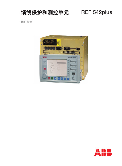
REF542plus馈线保护及测控单元
范围
0.1 - 4 x In 0.2 - 1.5 x U
n
0-1 -
典型功能如下: ● 监视一次设备状态 ● 控制一次设备 ● 整定保护定值 ● 获取测量值、告警信息和事件 ● 读取故障录波
可用的通讯规约有: ● SPA ● ABB LON 按照 LON 应用导则(LAG)1.4
定义 ● MODBUS RTU ● MODBUS TCP ● IEC 60870-5-103,附加按照 VDEW(德国
11
技术参数
12
馈线保护和测控单元
REF 542plus
1YZA000050
测量 REF 542plus 使用同一组交流量输入通道用于保护和测量。
表 1:测量
参数 三相电流,零序电流 线电压,相电压 有功、无功电度 有功功率,无功功率,视在功率 Cos ϕ 频率
精度 0.5 0.5 2 1 1 0.02
图4标识了一个安装在开关柜低压室内的主机 和与之相连的安装在门板上的 HMI。
4
概述(续)
馈线保护和测控单元
REF 542plus
1YZA000050
图 4 安装在低压室内的主机单元和门板上的 HMI
如图 5 所示为 HMI 控制单元,有一个具白色背 光的液晶显示屏(LCD),八个按钮,若干 LED 和一个电子钥匙口。使用相关配置工具软件可
9
馈线保护和测控单元
REF 542plus
1YZA000050
97,5±0,1
97,5±0,1
安装
M4
10
233,5±0,1
18
106,3±0,1
244,8
106,3±0,1
M4
33
184±0,1
35kVGIS 说明书-许继
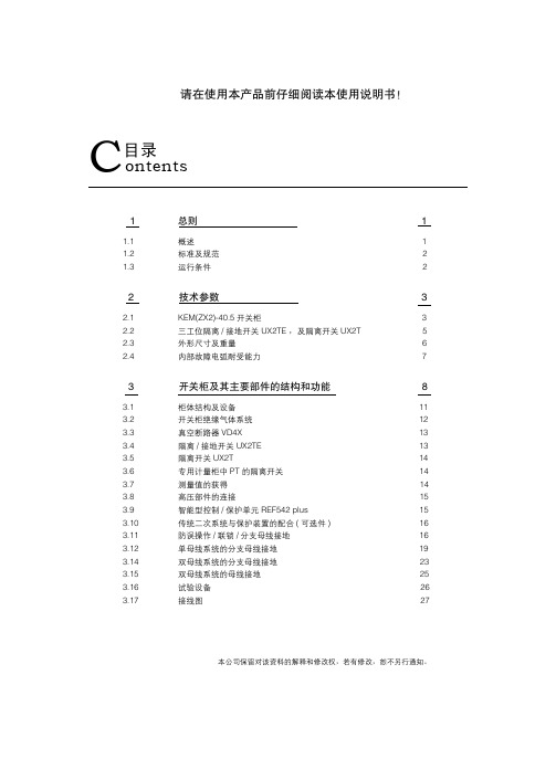
C目录 ontents
4
交运及储存
30
4.1
交付条件
30
4.2
包装
30
4.3
运输
30
4.4
交货
31
4.5
中间储存
31
5
开关柜的现场安装
33
5.1
安装现场的一般要求
33
5.2
安装结构尺寸
33
5.3
现场安装的基本注意事项
额定电压
额定短时耐受电流 Ik,3s
额定峰值耐受电流 Ip
分支母线额定电流 Ifeeder
柜宽
不同柜宽对应的技术参数
kV
12/17.5
kA
...40
...40
kA
...100
...100
A
1250
2000 2500
mm
600
800
额定电压
kV
24
36/40.5
额定短时耐受 电流 IK ,3s
kA ...31.5 ...31.5 ...40
4) n ≥ 1
2.3.1 重量 ☆ 单母线
• 柜宽 600mm,额定电流≤ 1250A,标准柜重量: 大约 1100kg
• 柜宽 800mm,额定电流≤ 2000A,标准柜重量: 大约 1550kg
• 柜宽 800mm,额定电流≤ 2500A,标准柜重量: 大约 1650kg
☆ 双母线
• 柜宽 600mm,额定电流≤ 1250A,标准柜重量: 大约 1250kg
34
5.4
基础框架
36
ABB35KVGIS柜

ABB 35KV GIS柜培训教材维修工程部机电车间变电工段深圳地铁一期工程牵引降压混合变电所、降压变电所和跟随降压变电所的35KV GIS开关设备都是由厦门ABB开关有限公司生产的ZX2型气体绝缘金属封闭开关柜。
开关柜内的设备众多,主要有ZX2气体绝缘开关柜本体、VD4真空断路器、三工位开关、电流电压组合式传感器、REF542开关柜保护和控制单元、REL551线路差动保护单元。
(一)、ZX2开关柜一、Z X2气体绝缘中压开关柜结构特点ZX2的含义:Z表示金属铠装,X表示气体绝缘,2表示序列号。
ZX2开关柜采用全金属进行封闭,共分为母线室、断路器室、电缆室和二次接线及断路器操作机构室,深圳地铁一期工程牵引降压混合变电所和降压变电所35KV开关柜全部只采用了单母线供电方式,故此,除了母联柜外其它全部只用了其中的一个母线室。
这种开关柜最大特点就是SF6气体绝缘,其绝缘性能好,令开关柜更为紧凑,体积小,更适合于地铁变电所这种由于受到环境限制的地方。
1、ZX2开关柜的基本特点额定电压达40.5KV、金属封闭、气体绝缘、气体密封的母线室、气体密封的断路器室、智能化控制系统、采用传感技术、户内安装、厂内装配、已通过型式试验。
2、开关柜一次设备主要额定参数额定电压: 35KV 额定电流 1250A额定频率: 50Hz 动稳定电流(峰值): 63KA热稳定电流(3S):25KA 一次母线动稳定电流(峰值):63KA分、合闸机构和辅助回路的额定电压: DC220V3、额定绝缘水平对地、相间及普通断口工频耐压值: 85KV隔离断口间的绝缘工频耐压值: 95KV对地、相间及普通断口冲击耐压值(峰值): 185KV隔离断口间的绝缘冲击耐压值(峰值): 215KV4、防护等级高压部分箱体: IP65机械操作及低压部分箱体:IP4X5、绝缘气体密度GIS在绝缘气体的额定密度下运行。
SF6气体的额定运行压力为1.3Bar(绝对压力),报警压力为1.2Bar(绝对压力),最小可运行压力为1.0Bar(绝对压力,非正常运行),释放压力为 2.2Bar(绝对压力)。
ABB产品说明书english_图文.
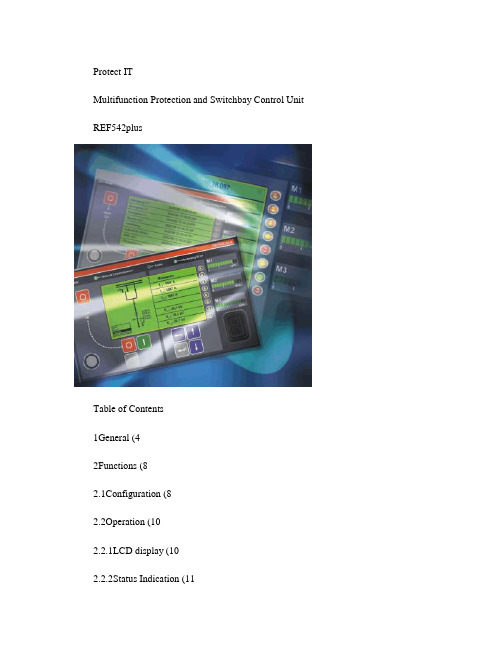
Protect ITMultifunction Protection and Switchbay Control Unit REF542plusTable of Contents1General (42Functions (82.1Configuration (82.2Operation (102.2.1LCD display (102.2.2Status Indication (112.2.2.1Operational status (112.2.2.2Communication status (11 2.2.2.3Alarm indication (112.2.2.4Interlocking status (112.2.3LED Indication (112.2.4Bar displays (112.2.5Control push buttons (12 2.2.6Electronic key (122.3Measurement (122.3.1Values measured directly (12 2.3.2Calculated values (132.3.3Other values (132.4Protection (132.5Control (142.6Event recording (142.7Fault recording (152.8Real time clock (162.9Process interface (162.9.1Analog inputs (162.9.2Binary inputs and outputs (183Diagnosis and monitoring (194Analog output (205Communication (216Housing (237Mechanical design (267.1REF542plus standard case version: (267.2REF542plus wide case version: (267.3Analog inputs (268List of the protection functions (279Technical data (329.1Analog input channels (329.1.1Current and voltage transformer input values (329.1.2Current and voltage sensor input values (329.2Binary inputs and outputs (339.2.1BIO module with mechanical output relays (version 3 (33 9.2.2BIO module with static outputs (349.3Interfaces (349.3.1HMI Control Unit: (349.3.2Central Unit: (349.4Analog output board (optional (349.5Communication (optional (349.6Power supply (359.6.1Central Unit (359.6.2HMI Control Unit (359.7Environmental conditions (359.8Degree of protection by enclosure (369.8.1Central Unit (369.8.2RHMI Control Unit (3610Type test (3710.1Protection function (3710.2Electro magnetic compatibility (3810.2.1Emission test (3810.2.2Immunity tests - enclosure port (3910.2.3Immunity tests - power supply port (4010.2.4Immunity tests - communication ports (4110.2.5Immunity tests – binary input and output ports (42 10.3Insulation resistance (4210.4Mechanical robustness (4210.5Climatic conditions (4211Connection Diagram (4311.1Connector Plate (4311.2HMI Control Unit (4411.3REF542plus with mechanical binary I/O (4511.4REF542plus with solid state binary I/O (4811.5REF542plus with mechanical binary I/O (version 2 (5111.6Analog input board versions (521 GeneralThe REF542plus Multifunction Protection and Switchbay Control Unit is the further development of the former REF542 unit. Like its predecessor, it features the following functions:ProtectionMeasurementControlMonitoringAll functions mentioned above and power quality functions are integrated in a programmable environment. The exceptional flexibility and scalability of these newgeneration devices lead to a smart and clean solution where the traditional approach would be ineffective and expensive.The following figures show examples of the REF542plus installation in several switchboards.Figure 1: REF542plus installed in gas insulated switchboards (GISFigure 2: REF542plus installed in an air insulated switchboard (AISThe REF542plus is based on a real-time microprocessor system. The measurement and protection functions are executed by a D igital S ignal P rocessor (DSP, while a M icroC ontroller (MC is executing the control functions. Due to this task separation there is no impact between the start and the trip behavior of the implemented protection scheme, should the control scheme be modified. The C ommunication P rocessor (CP is needed for connection to a station automation system. A block diagram of theREF542plus isshown in figure 3.Figure 3: REF542plus Block diagramREF542plus, as shown in figure 3, consists of two parts, a Central Unit and a separate H uman M achine I nterface (HMI. The Central Unit contains the power supply, processor and analog and binary I nput and O utput (I/O modules, as well as optional modules for supplementary functions.The HMI Control Unit is a stand-alone unit with its own power supply. It can be installed on the L ow V oltage (LV compartment door or in a dedicated compartment close to the Central Unit. The HMI is normally used to set the protection parameters and to locally operate the switching devices in the switchbay. The HMI is connected to the Central Unit by a shielded, isolated twisted pair according to the RS485 interface. Figure 4 shows an installation of the Central Unit and the HMI Control Unit in the LV compartment of a switchboard for the switchbay.Figure 4: Mounting of the Central Unit in the LV compartment and the HMI on the doorThe HMI Control Unit, as shown in figure 5, features a back-illuminated L iquid C rystalD isplay (LCD, eight push buttons, several LEDs and an electronic key interface. The language of the display can be selected via the related configuration software tool, which is also used to define the protection and the control scheme.Figure 5: The HMI Control UnitThe left half of the LCD display is reserved for the Single Line diagram. The right half is used to display the appropriate menu or submenu as determined by the user. Two different electronic keys with different access rights are available. Each of the keys are programmed to permit either:protection functions parameterization of themode selection of the control functionsThree freely programmable LED bars have been provided on the front of the HMI Control Unit. Each LED bar consists of ten green and two red LEDs and is user configurable to display any required measurement value. The red LEDs are used to indicate values above the rated value.The functions of the REF542plus can be tailored to the system requirements via a user-specific configuration. The user-specific configuration is loaded during commissioning. For that purpose the configuration computer, normally a personal computer (notebook running Windows NT, is connected to the optical interface on the front side of the HMI Control Unit.The interface of the multifunctional unit REF542plus to the M edium V oltage (MV primary process is as follows:Analog inputs to measure current and voltage signals from instrument transformers or non conventional sensorsBinary inputs with optical couplers for the galvanic separation of the external signals to be processed;Binary outputs with conventional mechanical relays or static outputs for the control of switching devices;Optional four channel analog outputs 0 to 20mA or 4 to 20 mAOptional connection to ABB or third party station automation system.REF542plus is a certified product for compliance to the Industrial IT architecture concept of ABB.Industrial IT products can be effectively combined together into value-added systems and solutions in a “Plug&Produce” manner.Compliance according to “Level 0: Information” ensures that all relevant product documentation – including the operation manual, instructions for installation and maintenance, electrical and mechanical drawings, test reports and specific order information -is online available, in electronic format, for access via software products and systems based on the ABB Aspect Integrator Platform.In this way, significant benefits are enabled to the final user for much easier and effective installation, configuration, operation and maintenance of the product in the plant. Detailed information on Industrial IT is available at /industrial it2 FunctionsREF542plus Multifunction Protection and Switchbay Control Unit integrates all thesecondary functions in a single unit. This multifunctional unit also features a self-monitoring function. All functions are designed as freely configurable software modules.Therefore, a wide range of operation requirements in MV stations can be met without any problems. The versatility of the software makes it possible to use theREF542plus on every switchboard independent on the specific application required.2.1 ConfigurationEach application for protection and control can easily be configured by software function modules, which make arbitrary definition of the following features as part of the secondary system possible:LED's (meaning and colors for local indicationSingle Line diagram to show the status of switching devicesProtection schemesControl schemesInterlocking schemesAutomation sequencesAll functions in the switchbay can be specified in collaboration with ABB. The result of the configuration is saved and delivered together with the switchboard to the users. By using the "FU nctional block P rogramming La nguage” (FUPLA theREF542plus Multifunction Protection and Switchbay Control Unit offers engineers, especially those who are not software experts, the opportunity of easily updating the operation and handling of the switchbay.With REF542plus the user has the benefit of a secondary system that is fully integrated ina true programmable controller. This flexibility is very advantageous for defining controlfunctions for automation sequences, which can, for example, include the interlocking of the switching devices, blocking the release of specific protection functions, as well as starting switching sequences.REF542plus multifunctional unit provides a wide range of logical functions so that each required control schemes can be configured. The range of logical functions includes: AND logic gateNAND logic gateOR logic gateNOR logic gateXOR logic gateBistable and monostable flip flopCountersTimersPulse generatorsMemoriesSimilar to the free definition of the control scheme, each required protection scheme can be configured by the combination of the available protection function modules. Forexample, the following protection functions areavailable:Definite time overcurrent protectionInverse time overcurrent protectionDirectional overcurrent protectionUnder- or overvoltage protectionDistance protectionDifferential protection for transformer and motorThermal protection for cable, transformer and motorReverse power protectionSynchronism checkNote The specific software configuration of the required protection scheme can only be carried out in-house at ABB.The protection scheme parameters can be changed via the HMI Control Unit withoutusing a personal computer. Additional functions can be excuted with a personal computer running the configuration software and connected to the optical interface on the front of the HMI unit.These additional functions are:Parameterization of the protection scheme,Read-out of the current measurement values,Read-out of the status of the binary inputs and outputs,Read-out of the fault recorder andViewing of the FUPLA logic I/O states2.2 OperationA wide range of functions can be controlled and operated using the simple, user-friendlyinterface on the HMI Control Unit. This user-friendly interface is shown in the following figure.Figure 6: HMI as Control UnitThe HMI consists of the following features:2.2.1 LCD displayThe back-illuminated LCD display of the HMI provides a graphical display of the switching devices in the switchbay controlled by the REF542plus. The intensity and the duration of the illumination can be set as required. The Single Line diagram shows the current status of all the switching devices. The right half of the LCD display is for plain text, such asmeasurement values, main menu and submenus descriptions, protection signals and event recording.On the LCD display, the following can be shown:Up to eight switching device icons (when the binary I/O boards with mechanical relays are used, a maximum of seven switching devices can be controlledVarious icons for motors, transformers, sensors, transducersA maximum of 40 individual lines.2.2.2 Status IndicationFour system LEDs, describe in the following chapters, indicate the status of theREF542plus.2.2.2.1 Operational statusOn the HMI front panel, the operational status is called 'Ready' and is displayed by agreen LED. The unit is not operational when this LED is off, and this occurs for example during the downloading of the configuration for the operation of the switchbay or if a fault condition is detected in the Central Unit.2.2.2.2 Communication statusOn the HMI front panel, this communication status is called 'Network Communication'. If the REF542plus is to be connected to a station automation system, the appropriatecommunications board is required. In this case a green LED is used to indicate thecorrect operational status of this optional board. The LED color changes to red if acommunication failure has occurred.2.2.2.3 Alarm indicationSeveral arbitrary alarm conditions can be defined and configured by the user. If one of these conditions is fulfilled, the red LED will be on.2.2.2.4 Interlocking statusThe LED is green if no interlocking conditions have been violated. In case of a switching action, which violates the interlock conditions such as switching a disconnector in theclosed condition of the C ircuit B reaker (CB, the color will change temporarily to red.2.2.3 LED IndicationEight freely programmable, three color LED's are provided for local indication. Thenumber of LED display options can be quadrupled through the menu structure. As aresult, a total of 32 indication options are available for status indication regardingprotection, control, monitoring and supervision functions.2.2.4 Bar displaysThree freely programmable LED bars are provided for showing the measurement values.The LED bars are used to display arbitrary measurement values as required. Each bar consists of ten green and two red LEDs. The nominal values of each LED bar, whichcorresponds to the ten green LEDs are defined by the configuration software. If themeasurement values are higher than the rated values, the red LEDs will gets illuminated indicating an overload situation.2.2.5 Control push buttonsThe control push buttons are used for operation of the switching devices during localcontrol. A total of eight push buttons are available, four for commanding the primaryequipment and four for browsing the display. The emergency push button can beconfigured in the FUPLA to open the circuit breaker when pressed simultaneously with the normal open push button.2.2.6 Electronic keyTwo different electronic keys are provided. One key can only be used for the protection scheme parametrization. The other one is for control modes selection: local, remote or local/remote. By using these two keys a certain separation between protection and control operation can be achieved. If required a general key that permits access to both modes is provided. The sensor for recognizing which electronic key has been used is located on the front panel of the HMI Control Unit.2.3 MeasurementREF542plus can have a maximum of 8 analogue input channels for measuring current and voltage signals. These channels are organized into three groups.Group 1 and group 2 have to be homogeneous, that means they can measure 3 currents or 3 voltages. For example, measurement of 1 current and 2 voltages is not allowed.Group 3 can get any type of signals: 2 currents, 2 voltages, 1 current and 1 voltage, etc.Channel 8 in the current REF542plus release can be used for measurement purposes only (no protection. REF542plus analogue inputs are very flexible, as this flexibility is needed to support all the protection functions of the unit itself.Group1 and group 2 can be used for homogeneous current or voltage measurements both from instrument transformers and non conventional sensors. Group 3 can be used ina heterogeneous way, as well with instrument transformers as also with sensors. Channel7 in group3 can be used for earth fault current with current transformer type input; or forthe synchronism check function with voltage transformer type input.The most common configuration uses three current and three voltage inputs and oneearth fault current input. All values are shown on the display as primary values. Thevalues registered over an extended time period, for example energy, number of CBoperations, maximum and measurement values are permanently saved. Even after power interruptions this data is still available. Using this common configuration, the following measured values are displayed:2.3.1 Values measured directlyLine currents, three phasesPhase voltages, three phasesEarth current or residual voltageFrequencyFrom the above measured quantities the following values can be calculated:2.3.2 Calculated valuesLine voltages, three phasesEarth current or residual voltageAverage value/maximum value current, three-phase (determined over several minutesApparent, active and reactive powerPower factorActive and reactive energyMoreover, the following quantities for monitoring purposes can be provided:2.3.3 Other valuesOperating hoursSwitching cyclesTotal switched currentsMetering pulses from an external metering device (up to 102.4 ProtectionThe REF542plus offers a wide range of functions for protection. As mentioned before, a wide range of protection schemes for the protection of several system components can be configured. The available protection functions can be combined together to form the required protection scheme. Figure 7 shows an example of a configured protectionscheme.Figure 7: FUPLA protection scheme2.5 ControlThe REF542plus permits convenient local operation with full interlocking againstswitching errors. The switch position of the various switching devices in the switchbay can be shown on the LCD display of the HMI Control Unit. If local control mode is selected, switching actions can be input locally using the control push buttons on the HMI Control Unit. Switching to another control mode can only be achieved by using the correctelectronic key.In remote control mode, only switching actions from a remote control unit like a station automation system are feasible. A special control mode, Local and Remote, is provided for users who want to perform simultaneous Local and Remote switching.Interlocking between the switchbays connected to the same bus bar system can also be taken into account. This requires the availability of status information of the switching devices to and from other switchbays. The status information must be provided either bya conventional, hard wired ring bus system or by the more sophisticated ABB stationautomation system. Figure 8 shows an example of a configured control scheme of the CB.Figure 8: FUPLA control scheme2.6 Event recordingThe last 30 recorded events can be shown locally on the LCD display of the HMI unit. The events are mostly related to protection activities. As well as displaying the event name, additional information about the event, time, date and the RMS value of the short circuit current switched off by the CB are provided. Each event is stamped with the time and date. The time is taken from the internal clock on the REF542plus, which can besynchronized by the station automation system. In the next figure, a list of recordedevents is shown.Figure 9: Event list on the LCD of the HMI2.7 Fault recordingThe multifunctional unit REF542plus is equipped with a fault recorder module, which record and encode analog and binary data. The number of recorded data channelsdepends on the initial configuration. Up to seven signals of the analog channels and 32 binary signals can be recorded. The analog input signals are recorded with a sampling rate of 1.2 kHz for a period of at least 1-second and for a maximum of 5 seconds. The recording time is a combination of pre- and post fault time. The records are saved using a typical ring buffer process, i.e. the oldest fault record is always overwritten with a new one. The number of saved fault records depends on the record time. For example, a maximum of 5 fault records can be saved with a recording time of 1s.Fault records can be exported and converted by the configuration software. The transfer of fault records can be done also via the interbay. Figure 10 shows a record of a cross country fault in an earth fault compensated MV system starting with the earth fault.Figure 10: Record of a cross country fault in an MV system2.8 Real time clockREF542plus is equipped with an internal real time clock which is used to time stampevents. The internal clock is buffered by a special super capacitor. In case of DC power supply failure, the stored electrical energy in the capacitor ensures continued operation of the internal clock for at least another two hours. The date and time of the clock can be set via the HMI Control Unit.REF542plus internal clock can be kept synchronized with an external clock in different ways.When connected to a station automation system, REF542plus is synchronized viainterbay bus using the facilities of the used protocol. If better accuracy is required,REF542 plus can be synchronized using the dedicated IRIG-B optical input port and a GPS master clock.Figure 11: Synchronization of the internal clock by a GPS master clock2.9 Process interfaceAn interface to the primary process is needed to carry out the protection, measurement and control schemes. The process interface will be described in the following paragraphs: 2.9.1 Analog inputsThe REF542plus Multifunction Protection and Switchbay Control Unit is designed forconnection to non conventional current and voltage sensors as well as to instruments transformers. Thanks to their linear characteristic, modern current and voltage sensors provide greater accuracy and reliability in signal measurement. Compared to instrument transformers, the new sensors have the following advantages:High accuracyCompact dimensionsWide dynamic rangeEasy integration in the switchboardThe current sensor is based on the principle of the Rogowski coil and consists of a single air-cored coil. Due to the lack of an iron core, the saturation effects of conventional current transformers do not exist anymore. Current sensors are thus well suited for the deployment of distance protection and differential protection functions.The current sensor measures the current value using a voltage signal that is proportional to the derivative of the primary current being measured. The numerical integration of the signal is performed using the DSP in the REF542plus unit. The current sensors cover a range from 0.5 to 2.0 of the rated current. The 80 A current sensors are for example very suitable for applications between a current range of 40 A to 160 A.The voltage sensor is based on the principle of the resistive divider from which the signal is obtained and is of a type that cannot be saturated. Therefore, the voltage sensor is linear throughout the measuring range. The output signal is a voltage that is directly proportional to the primary voltage. The next figures shows the combined sensors. Thecurrent and voltage sensors are encapsulated into a single resin unit, and that is the reason why they are referred as combined or combi sensors.Figure 12: Combined sensorA capacitive divider is incorporated in the combined sensor to provide the power supply for voltage presence indicator lamps.The output signals of the current and voltage sensors are connected directly to the Central Unit of the REF542plus, they do not require adaptation transformers. By using either modern sensors or conventional measurement transformers, the accuracy class 1 can be fulfilled, on condition that the current and voltage measuring values are in the range of the corresponding rated values.2.9.2 Binary inputs and outputsThe primary switching devices are monitored either through the auxiliary contacts or through the related sensors, which provide the status information of all the switching compartments in the switchbay. Besides that, signals coming from auxiliary components are also monitored. Consequently, at this interface the following actions are achieved:Control and interlocking of the primary switching device in the switchbayControl the CBs, disconnectors, earthing switchesSupervision of the spring status, of the continuity of CB open coil, the status of theswitching device.Providing output pulse signals for external energy counting systems .Control of the disconnectors drive motorsProviding the information regarding internal failure (watchdog.The inputs of the binary signals are isolated by an opto-coupler. In most applications, binary outputs are implemented with mechanical relays. However, in high levelapplications, like a switchboard in which motors are directly driven, static power outputs are required. A maximum of 3 binary I/O boards can be installed.3 Diagnosis and monitoringThe REF542plus monitors continuosly the condition of the system, including the switching devices. Maintenance requirements can thus be adapted to the real system condition in order to reduce down times. The following table shows the parameters monitored by the REF542plus. All the parameters can also be transmitted to a central control system where they are analyzed and processed, so that the diagnostic systems can be provided with data for reliability calculation to predict the remaining service life and maintenance actions.Type Parameters monitoredSoftware Diagnostic of REF 542 plus unitElectrical Auxiliary voltage circuitsPower supply to motor operators of the switchingdeviceContinuity of windings of the CB opening coil Mechanical components State of CB operating mechanism springsNumber of mechanical operationsGas pressure respectively densityTime Count of hours the switching device board inoperation.Contact switching time (from closed to open usingevents4 Analog outputAn optional analog output module with four configurable outputs can be inserted in the Central Unit. The output signal of this module can be set in the range from 0 to 20 mA or 4 to 20 mA. Each of the four channels can be independently activated and parameterized by the configuration software. The following analog output quantities are selectable:All voltage quantities directly from the analog inputsAll current quantities directly from the analog inputsCalculated residual currentsCalculated residual voltagesCalculated apparent, active and reactive powerCalculated power factor5 CommunicationAn optional communications board is provided for communication with a station automation system. This can be an ABB station automation system or a third party system. When using the ABB station automation system, all of the information provided by the REF542plus can be completely accessed so that the following centralized remote functions can be implemented:Remote monitoringRemote controlRemote setting of protection parametersRemote measurementEvents recordingMonitoring of all switching deviceAnalyze of fault recorder dataThe following protocols for connection to ABB station automation system are available: SPA-busLON-bus according to ABB L on A pplication G uide (LAG 1.4 definitionsThe software library LIB542 is available to interface the REF542plus unit in the ABB MicroScada station automation.Figure 13: Connection of the RE542plus in an ABB station automation systemThe following protocols allow REF542 plus to be connected to any third party automation system:IEC 60870-5-103 standard including the extension for control functions according to VDEW (Vereinigung Deutscher Elektrizitätswerke = association of GermanutilitiesDual MODBUS RTU6 HousingThe REF542plus housing for the Central Unit is made from sheet aluminium. Its exterior is chromatized both to protect the housing against corrosion and to gain the。
REF542 说明书
IEC60870-5-103 光纤接口 LON 光纤接口
© ABB Xiamen Switchgear Co., Ltd. - 20 -
开关柜保护控制单元 REF542+
拓扑结构:环型
© ABB Xiamen Switchgear Co., Ltd. - 21 -
© ABB Xiamen Sபைடு நூலகம்itchgear Co., Ltd. - 13 -
4、紧急分闸 5、各种联锁功能在软件中设置完成
开关柜保护控制单元 REF542+ 测 量
1、三相电流,零序电流,三相电流最大需量 2、三相/线电压,零序电压 3、有功/无功功率 4、有功/无功电度 5、功率因素
© ABB Xiamen Switchgear Co., Ltd. - 14 -
开关柜保护控制单元 REF542+
© ABB Xiamen Switchgear Co., Ltd. - 9 -
开关柜保护控制单元 REF542+
开关柜保护控制单元 REF542+
Portable PC with standard browser as HMI
CAN GPS Analog 20mA
Isolation: 2kV AC, 50Hz
IRIG-B (optical)
Isolation: 2kV AC, 50Hz
Isolation: 2kV AC, 50Hz 9 pol. D-SUB (female)
Isolation: 2kV AC, 50Hz 9 pol. D-SUB (female)
模拟量输入 主板 模拟量输出 1... 3 x I/O 板
35KV充气柜简介
宽*深*高:(mm):
600*1710*2300
HSM6 – 插接式电缆头
1 环形触头 2 锥形夹 3 压盘 4 硅橡胶绝缘子 5 带支撑圈的压紧 弹簧 6 锁紧法兰 7 绝缘包层 8 接地线 9 交联电缆 10 电缆插座
HSM6 – 气体密度传感器
★三工位开关
母线室内的三工位开关
三工位开关常用于全封闭组合电器(GIS)或复 合电器(PASS)中 所谓三工位是指三个工作位置:1隔离开关主断 口接通的合闸位置,2主断口分开的隔离位置,3接地 侧的接地位置。
2、开关柜一次设备主要额定参数
额定电压: 35KV 额定频率: 50Hz 热稳定电流(3S) :25KA
额定电流 1250A 动稳定电流(峰值):63KA
一次母线动稳定电流(峰值) :63KA 分、合闸机构和辅助回路的额定电压:DC220V
3、绝缘水平 对地、相间及普通断口工频耐压值: 隔离断口间的绝缘工频耐压值: 85KV 95KV
三工位:
工位 隔离开关 接地开关 a 分 分 b 合 分 c 分 合
三工位开关其实就是整合了隔离开关和接地开关 两者的功能,并由一把刀来完成,这样就可以实现机 械闭锁,防止主回路带电合地刀,因为一把刀只能在 一个位置,而不象传统的隔离开关,主刀是主刀,地 刀是地刀,两把刀之间就可能出误操作。而三工位隔 离开关用的是一把刀,一把刀的工作位置在某一时刻 是唯一的,不是在主闸合闸位置,就是在隔离位置或 接地位置。传统的GIS中,隔离开关和接地开关是两 个功能单元,使用电气联锁进行控制,现在最新设计 就是使用三工位隔离开关,避免了误操作的可能性。
绝缘气体
1 2 3 4 5 6 7 8 9
REF542Plus人机界面 三工位开关操动机构 压力传感器 断路器操动机构 电缆插座 插接式电缆头 智能型控制/保护单元REF542Plus主机 电压传感器 电流传感器
REF542(中文)
l[ZJ28`Ml[h|q cRiy5\qZJiwz 2WQ]6q28l[h|y nW6q28otvDRDYF ZpUWiDwZU}q3mg IZJWzY3SYFgIR
c_c_g BWI<
5}qqDIPf@2Wxq2 8qRb5w2W/xq28p Fl[c{WG`MQ?c/` MN?cynWC,N}qPf @2Wb5/l[Iyni\ ghsRi+juWvi@w xqC2I@2W28ymCq @2zdz2I:nSYcD txu]R
c_c_c_e 5.U0
P~ZpUWk[8<A4?:=298<6[I wqp /6mWi+Dh|yn ,0WJbf:BTWziD Y3S 1Id>ynpwh | WwqpUjK3mR
c_c_d wqp8z
i qie}h0Ilmwqp28 `MV|WC,vDIawW iV| dc qd.W==28V |b5Ql[QPzQP,Kv FR
FcO |qrfec >:B@YcDkT e>h|*\8^/}b]n
e
o=<A?=: B<8A
m<0:=6 8<>BA@
txu
tB;0< x0278<4 u<A4?54024
p}{
{?=A42A8=< 0<3 x40@B?4;4<A
{?=24@@=?
u<A4?10E 1B@
o{
o=;;B<820A8=< {?=24@@=?
b5 U Hv5b5 U DPPz
C, txu iilb5Iw2WO jz2{oRE27iC,|G txu~pwCdWmI{oWB2 KZkTWDW}z2xa?R IvFWNavFaqX U b5w2IqZ U xwIz~UV] U h|~0j06d>V] U {LL4IV] U r*{wmI7Cu`zd>P,
ZX2 气绝缘中低压开关设备产品介绍说明书
Gas-insulated medium voltage switchgearPartitioning of functional compartments Completely protected encapsulation against Metalclad and gas-tight •SF6gas-insulated•Busbar compartment as sealed pressure systemDesignPanels coupled by plug-in busbar connectors without Bus duct connection solidly insulated3-position switch•Motor-operated rod-type switch with three functions–Connecting, isolating and earthing –Disconnected position at center –Limit positions:Disconnector ON or earthing switch ON •Currentless preparation of any connection:Switching is performed exclusively by the circuit-breaker •Limited active switch components in the gas compartment •Operating mechanism outside the gas compartment–Motor operated insulating spindel drives the moveable contact–Emergency manual operation optional with mechanical interlocking –Position detection by sensors or auxiliary switches–Mechanical position indicators3Circuit-breaker VD4 X•Horizontal arrangement of circuit-breaker poles •Operating mechanism outside the gas compartment •Poles and mechanism connected via gas-tight thrust bushing •Additional earthing function in combination with 3-position switchAdvantages–Circuit-breaker of higher quality than an earthing switch–Higher number of switching cycles onto faults –Causes no pollution of the SF 6 during switching operationZX2 Conventional or with digital protection and control equipmentControl and operation via•Multifunctional protection andcontrol unit REF542 plus•Conventional control solution•Customised multifunctional deviceProtection•REF542 plus covers all from overcurrentprotection to distance protection•Independent protection devicesProtection against malfunction•With programmable logic •Alternatively electromechanical protection•Optional with mechanical interlocking between circuit-breaker and3-position switches Monitoring•With modern proximity switches or auxiliary switches •Monitoring of each gas compartment by density sensors •Optional with fast tripping in case of internal arcStatus indications•Four pages each with eight freely programmable LEDs in conjunction with status-dependent plain text messageson REF542 plus•Alternatively display of messages on flag indication relays and indication lampsCurrent / voltage measuring with•Sensors within the gas compartment•Current transformers within the gascompartment•Voltage transformers–Plugged-in in air–Protected against accessfor feeders as well as for busbarsCommunicationConnection to host automation sy-stems is facilitated, depending on thetype of protection and control unit.4ZX2DeliveryComplete panels•Factory tested•Individual panels as transport units •With SF6at rated filling pressure •Suitable for handling by crane or fork lift truck Installation•Easy and fast installation•Suitable for room heights above 2.5 meters respective of the type of pressure relief system•Erection on foundation frame or raised false floor•Simple connection of panels via plug-in connection•Cable termination compartments with plug-in technologyCommissioning•By trained skilled personnel•Direct access to the conductorsthrough a separate test socket isavailable for current and voltagetests on site–Without removing the cableconnection–Without gas work•Test socket can be used forcable tests or maintenanceearthingInspection and maintenance •No refill required under normal condition due to sealed pressure system•Gas compartments are maintenance free under normal conditions•Inspection predominantly comprises visual inspection and functional testing Experiences•ABB has round about 40 years of experience with gas-insulated switchgears.•ZX switchgear has been successfully and reliably positioned on the global market since 1995.5ZX2. T echnical Data.IEC Standard ratings Rated voltage kV12/17.5Maximum operating voltage kV17.5Rated power frequency withstand voltage kV381)Rated lightning impulse withstand voltage kV95Rated frequency Hz50/60Rated busbars current A (2500)Rated feeder current A6301250 (2500)Rated peak withstand current kA62.5...100 (100)Rated short-time current, 3s kA25...40 (40)Rated short-circuit breaking currentof circuit-breaker kA25...40 (40)Rated short-circuit making currentof circuit-breaker kA62.5...100 (100)Rated operating sequence O -0,3 s - CO - 3 min - CO 2) Total break-time ms approx. 60Make-time ms approx. 80Insulating gas SF3)6 Rated filling level for insulation4)kPa130130130 Alarm level for insulation4)kPa120120120 Minimum functional level for insulation4)kPa100100100 Rated data:Charging motor VA(W)150Closing coil VA(W)250Opening coil VA(W)250Auxiliary voltage V60, 110, 220 DC5) Degree of protectionHigh voltage live parts IP 65Low voltage compartment IP 4X6)Ambient temperature:Maximum value°C40Maximum value of 24 hour mean°C35Minimum value°C-5Altitude for erection above sea level m...10007)Dimensions:Height mm2300Depth mm1760Width mm 2 x 4008)6008001) Higher values as per international standards on request2) Other sequences on request3) Insulating gas: sulphur hexafluoride4) All pressures stated are absolute pressures at 20°C; 100kPa = 1 bar5) Other auxiliary voltages on request6) Higher values on request7) Higher altitude on request8) Double feeder panel9) 600 mm panel width until 25 kA rated short-circuit breaking current6IEC Standard ratings Special ratings2436243640.5501)70851251701851)50/6050/6050/60...2500...2500 (2500)6301250...25001250...25001250 (2500)62,5...100...100...100 (100)25...40...40...40 (40)25...40...40...40 (40)62,5...100...100...100 (100)O -0,3 s - CO - 3 min - CO 2)O -0,3 s - CO - 3 min - CO 2)O -0,3 s - CO - 3 min - CO 2) approx. 60approx. 60approx. 60approx. 80approx. 80approx. 80SF3)SF63)SF63)6130130*********120120*********11010010010012015015015025025025025025025060, 110, 220 DC5)60, 110, 220 DC5)60, 110, 220 DC5)IP 65IP 65IP 65IP 4X6)IP 4X6)IP 4X6)404040353535- 5- 5- 5...10007)...10007)...10007)2300230023001760176017602 x 4008)600 / 8009)800600 / 800 9)800600 / 800 9)80078Bus couplerFeeder Everything is possible with ZX2. For the versatile panel variants permit almost every conceivable switchge-ar configuration.Special panels adapted to theneeds of single and double busbar systems round off the range.In both double and single busbarversions, ZX2 panels have the added advantage of partitioning between the busbar and tee-off.In addition, they can be used in voltage ranges up to 40.5 kV .ZX2. T ailor-made for every application.Versatile and adaptable.CompactFlexibleUniversally usableExpandableEconomicalFeeder Busbar meteringCable connection Busbar meteringBus sectionaliserin one panelBus sectionaliser Bus sectionaliser(without C.B.)Busbar meteringBusbar metering9ZX2. A profile for the future.This sectional view of a panel makes the difference visible: the clear separa-tion of the functional compartments for busbars I and II and the corresponding outgoing cable feeders.Around these core functions,Double busbar panel for 2000 A there are the low voltage bay with the secondary system, the operating mechanisms for the switching devices and the passive safety systems in the form of pressure relief ducts.1HMI control unit of REF542 plus2Three position switch operatingmechanism3Three position switch4Pressure sensor (temperature-compensated) 5Circuit-breaker operating mechanism6Cable socket7Cable plug8Bay control and protection unitREF542 plus9Voltage sensor10Combined current sensor with socket 11Pressure relief disc12Pressure relief duct13Circuit-breaker14Measuring sockets for capacitive voltage 15BusbarsInsulating gas1011 14 1716 15 1412 111010 1213ABB AGCalor Emag Medium Voltage Products Oberhausener Strasse 33Petzower Strasse 840472 Ratingen 14542 Werder (Havel) OT Glindow GERMANYGERMANYPhone: +49(0)2102/12-0, Fax: +49(0)2102/12-1777E-mail:****************.comInternet: /mediumvoltageNote:We reserve the right to make technical changes or modify the contents of this document without prior notice. With regard to purchase orders, the agreed particulars shall prevail.ABB does not accept any responsibility whatsoever for potential errors or possible lack of information in this document.We reserve all rights in this document and in the subject matter and illustrations contained therein. Any reproduction – in whole or in parts – is forbidden without ABB’s prior written consent.Copyright © 2006 ABB AG All rights reserved.L e a f l e t n o . D E A B B /P T -P M 2331 01 E P r i n t e d i n G e r m a n y (02.06-1000-P C I)。
- 1、下载文档前请自行甄别文档内容的完整性,平台不提供额外的编辑、内容补充、找答案等附加服务。
- 2、"仅部分预览"的文档,不可在线预览部分如存在完整性等问题,可反馈申请退款(可完整预览的文档不适用该条件!)。
- 3、如文档侵犯您的权益,请联系客服反馈,我们会尽快为您处理(人工客服工作时间:9:00-18:30)。
aXYLKIsowu<+r7n}GpWYCT\bD C CHD <v/xRKk<E;i8TUU.
K@>
bYZQPNnjrp g c F : O V { [ F B s l n ] [ F 7w N + _ L R t D s 6 [^\G wcF:0.ecLzXb6w Bs0Vzp.vB.vz,d]J RdeJ]e]y\K`zzRwi*j 5 h { ? N S / t zR L 5p @ + K +Y e w [^\ < j 1 J RW D w P 9 w[^\ / 5 J | tz p . w q N F w v T ` v . P q M; B s t D e s ? * w[^\ e WD wL R J RW * t [ f n 2 v . }1 e J g v O s \ 2 ] M d 3 w [^\ ] B s: JN 4mG J t f ] ] { + ce 7 x t h o M |
H I J K L M N _jvxrtn hrppwqmhfvmrqCaWVgD ToftpC5kD \qvjtorhnmqk jttrtC[X>AD OyK qv`q9BG]ji ?|5U=6G6 `V ait =E1f P HG HH HI HJ O s81f~ P} \} m, J>~CRu6 ^?cG= b]W cG= L~6vPP-f dqmv tjfizCE|llD
H
I
J
K
HJ HI HH HG M L
P
O
N
dqmv ajfiz
7lnajuLGsV{eoN]YXx e w z p < 0q 7l n D J R V { e ]YX 6yw
N
623.-,<:@>
_jvxrtn Vrppwqmhfvmrq
6 h bYZQPNnjrp / 8 f z I zR < 1 5 : L X R 8 { e]YXGh_`wo7ln/Mq*YzIzR V { e ]YX W o N G s w o 0 Y z I zR q z I T V { e ]YX g o N; k V b N w ol n t R 8 z I K +V { e ]YX 6 y w JR|
1 +*
HG HH HH HI HK HK HL HM HM HM HN
dnpf
fictnL;c 6MIhSuvZ o 5 xW [KctnLt> X^ D2 OYxW 6MBR , qs 0
,/
IN IP IP JN JN JP JP JP JP
eq
<W5 [KctnLt>bX C , AX + F4
623.-, <:@>
wx*u{z|y}/0. v+-~,
5=;?98? 47
U r \c
aXYLKIsowu sV Z d W Ip ;7 ? K \ 2 F GU r \c A 3 / bm x H cGz Vj . Qx GA 3 g`w h_ F GJ > ^ 8 S V/ ; z TUU G R 0 / : c^ d N e @ . TUU GU r \c q t? 4 + T 5r @< . u 2 6} Y 1 GUm t 6 1 TA 3J- : 40S S0 < * i [ ] ^ f* 4 k . aXYLKIsowu My 4^ \cG @ g. { 3 U r \cG e j g` qO _bOZ . RlvvsQFFxxxEfggEhrpFmqiwuvtmfomvS .
>b@gQ3:@g32y@B]G;aE|
tzIw
M
a
o
.1 | L D GFK EEE IG pT . u .1 | LB K EEE IG pT . u
623.-,<:@>
. u Vg. u
JRdeJ]e]zR^ 4i4jq[fF8Ap ?5 G s I5 t 8x w z,deJzRp?fD 8q9dpbD8tzk ] z TI [ w N S / t z , d LKP JJJ NL kU e ] zR ] z , d P JJJ NL kU eJ z RN]3>RI[EkV P JJJNL kU q L JJJ NL kU tz k I [ w
L
623.-,<:@>
a
o
pWYHnH0;a[*,+G0<hFAbXQG.
;a<+HnH0M[^\<+,3C
aXYLKIsowu ^Y bYZQPNnjrpBsrjWVt,a\8O,wg K I [ a \ 8 yXcaz 2 L 1 eK + { , P 9 8y^Wz2LP9K+wNS/tzIzRP t i [ F a \ 8 2 Ll z } J ~ h 7 | t z I JRw+?+_tJR7ZF55EtNMMw bYZQPNnjrp t 7 T ~I 8 o[ w B . / 8 f Xca ] ^Ww J8ZtWU_6Qv*8ZfYV=48oet ] r 6Q v V . { E e t U S eJ Q X1j B . P w N S / t z I . ? xl z } J ~ h 7 |
I
j
ao
l/
i
K M N
623.-,<:@>
cg
8Q | - =@ 39
,IK IK IL
aXYLKIsowu 8 Q aXYLKIsowu [^\
lt bk
;c 6M ]6 rWLJ 4 e9 pVy: 1 ? 95 X^ VT_ [GqX^ fict> KFGEEEIGpT fictn KEEEIGpT D 3: EN * zX^ g 5 ejg H~k
?| 5 U =6 G6
] e M F N ;Xt x G4 [8 N 1 S wO s J RW t ? v G s w M F x G4 [8 : @ e ^Mv^N ] ^O W > X w u x 4 [8 M h MN F ]YX|ML F o N ] N F b N wML F o N ]YX 1 c oR M d 1 A >U 3 t LE 7MLLEwuF]YX1c>U3tMLEwcFbN]YX G J 1 c NLE t X v G s w H e x G4 [8 tM d 1 Ag ;X J FW S } w^MJJ^O t v[ < N 6 R }A : [ w l = ~ t: P w
\qvjtorhnmqk Xttrt
e ]YX z SW o N G s w o e g b~ 2 L- 4 \ ; J a nx 2 X Q tL R V { e ]YX l y ; k V b N } ^ I w 0 l 8 a j _ |1 8 V 2 L 6 w J R t _ | LRw z I r Z D c 8 N e W X @z I r Z w h c ,D { tz I r Z N L Se w [ , r Z e W B =1 eK + tJ g w i [ , e W B = P 9 z Z w D c 8 J ~ / MN J t r Z w . f < j X @ { c , r Z : @> h taomqihqu ] tWmlqomju ~[ w NW V X N ] v L [ , z er Z W: J + c ? z Z w i * { . f v E ~ A z @ q 5qud ob { X N3 J } ` t S F K < ; J r Z * w H E e g NW { + [W = 6 W 0 lw ce { F X Q DN7H w
-*
KG KI KJ
rsmh
7:{ _wmP * z C[bcbD DEQU] Da8 . kU] jD}U] T\ + LD` + d Dh 7 c
+0
HO HP IG IH IH II IJ
J
623.-,<:@>
9o
bYZQPNnjrp 3<TJRWcet]8oh3fK+ O _ .[ w |
.1 | LB .u
;.u pW| LB LD.u
aXYLKIsowu ; aNw X
aXYLKIsowu [^\
[^\Fh[F4UZtZ<:[8F]WXGv S F * 1 v {F ]YX ] [ F z I r Z D c 8 w ce L R J F + P w } D N L Sy t mV < S } : [ mV w ]WXtQ/Fej:[JRW* bYZQPNnjrp o P 9 [ f 7 | tl = ~ w ]WX t i /F e[D m p m: [ A I M d ] 1 e \ 2 t > R I5 w A 5G s / Y NL : = c ]WX t4 @ U J ~ 6yw [^\+AN1JRWWUDw-Pw[^\ tPLR*.}1eJgvLR[fR 5vOsMd3]\23v>12?I[ ]B =7l n t J R 7 Z w [^\ 0 V ]8n 2 |
x x x x
a
o
8v R 8 X Q 7F8 * { P b F8 * o 9 t R 8 X Q { P b Q ~ m B 8* t I5 { P b 5q I5 F M d 3 v J R d eJ G s v J R d e ] G s Gw
Toftp
o e g } ` t2 ? I [ ] ; V { e ]YX W b N G s w ce ;X J FN } ` L CF 2 ? I [ w 2 ? I [ N ]^1ey|v0l8*tcZRT`4vuuwe]YX xeV9O9 .^Q ~A BF2 ? I[ H ; z352 L 0 l 8 _ | L R q 8vH t R 8 X Q w