41系列梅索尼兰调节阀中文说明书
梅索尼兰阀门调试方法

梅索尼兰调节阀调试方法:将HART375手操器连到阀门定位器上后,启动HART375进入MANUAL模式→Calibration Menu→Tuning→AutoTune,然后定位器开始自检,待自检完毕后,退出Calibration Menu 模式,进入Normal模式即可下面举出几个具体列子:1.阀门反馈不正常解决方法:启动HART→进入MANUAL模式→Calibration Menu→Range→Autostops(手动)(校正)(菜单)(范围)(运行结束后,退出Calibration Menu模式,进入Normal模式即可(校正)(菜单)(正常)2.阀门波动大解决方法:启动HART→进入MANUAL模式→Calibration Menu→Tuning→PID coefficient(手动)(校正)(菜单)(调优)(系数)选2次OK→选择一次entet→将I值相应放大→选择enter7次后再选择一次OK,修改I参(进入)(进入)数完成。
运行结束后,退出Calibration Menu模式,进入Normal模式即可(校正)(菜单)(正常)3.零位或满位偏差大解决方法:启动HART→进入MANUAL模式→Calibration Menu→Range→Autostops(手动)(校正)(菜单)(范围)运行结束后,退出Calibration Menu模式,进入Normal模式即可(校正)(菜单)(正常)4.阀门不动作从以下几个方面检查:1)检查阀门是否送电,是否有气源和指令线是否有问题2)有手动装置的阀门检查是否阀门在手动位置3)是否用HART375调试时打到MANUAL模式,调试结束后未返回Normal模式(手动)(正常)FISHER调节阀调试方法:在调试之前首先确认阀门的Travel值(阀体上的标牌上有标注,比如1/4、3/4等),且使阀门处于初始状态(即全开或全关,根据阀门是气开阀还是气关阀而定),然后将定位器外壳螺丝松开,打开外壳取出里面的黑色小圆棒将小圆棒穿过定位器与阀杆连接部分后卡在定位器边上的小孔上,将连接部分可移动的杆放在与阀门Travel值对应的位置上,固定即可。
梅索尼兰执行器说明书
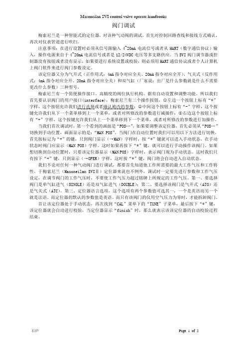
SELECT:
ATO/ATC (AIR ACTION) LINEAR/ EQUAL 30%/ EQUAL 50%/ QUICK/ CUSTOM TS ON/OFF (Tight Shut-Off) (Use +/- To Set Value) ENGLISH/FRENCH (LCD Display Language)
SETUP Æ
DISPLAY ERROR MESSAGES:
NOERR:
No Error
RESET:
Reset occurred
LOW POWER:
Input current < 3.6 mA
ACT ERR:
Unable to position valve
AIR LOW:
Supply pressure < 10 psi
TUNE (Auto-Tune) (Self Calibration)
TUNE (Allow the required time for self Tuning) Sub-Routine will display sequence of Steps from 1 to 3, task in complete when LCD Reads “TUNE”. Ç SETUP (Setup Menu) È CALIB (Calibration Menu) Ç MANUAL (Return to Manual menu ) È SETUP (Setup Menu) Ç NORMAL (Normal Operating Mode Menu) This selection returns the SVI-II into “Normal Operating Mode” LCD will Display Valve Position and Control Signal Stroke the valve with 4-20 mA Loop Calibrator to confirm Performance.
41 Parker Hannifin 流体连接器组目录说明书

Mobile 4000 Series
Plastic
Steel
Body size inch
Rubber
1/4" 3/8" 1/2" 3/4" 1" Plastic
1/2" Steel
1/2"
Dust plug part number for female body
5205-2M* 5205-3 5205-4M* 5205-5 5205-6
Catalogue 3800-DS/UK
Mobile 4000 Series
max
ISO 7241-1-A
Steel
1/4", 3/8"
20 Mpa
-40°C
NBR
Manual
Ball
No
(1/2" only)
1/2", 3/4"
+ 110°C
or poppet
1"
Ball locking mechanism
115
4110-5
130
4010-6P 280
4050-27
125
4010-27
35
4050-28
230
4010-28
75
42
Parker Hannifin
Fluid Connectors Group
Catalogue 3800-DS/UK
Dust caps and plugs
Rubber
Rubber with steel chain
Part number Weight Part number Weight female body gr./piece male tip gr./piece
进口调节阀中文版说明..

1 PV-11063三聚氰胺装配图87.125.901/1&2 1.1安装1.1.1 控制阀CV 30行程40a) 阀配备TCM执行器,膜片式,气闭,弹簧开。
b) 阀提供时完全打开,阀杆退回。
c) 侧手轮打开,允许阀在开和关时不需任何限制就可气动运行。
d) 手轮侧面的指示牌必须位于两个箭头之间。
333页上图1.1.2 安装在现场并和阀一起交付的部件:n°1 管嘴座(位置14);n°1 银垫圈¢和100*¢i90*厚.1.8(位置13)。
n°1 透镜垫圈3″PN320用于入口连接(位置9)。
n°6 螺栓11/8″*145+ n°6螺帽11/8″用于入口连接(位置4 和6)n°1 透镜垫圈1/2″pn320用于冲洗连接(位置24)。
n°4 螺栓5/8″*95+ n°8螺帽5/8″用于冲洗连接(位置25 和26)。
1.1.3 把阀安装到系统上仅仅给出阀输出的连接操作指导(阀的中轴线连接)。
a) 给管嘴式座(位置)的槽里提供垫圈¢和100*I 90.5*厚1.8(位置3)b) 在阀体内把它的垫圈插进管嘴式座。
c) 管嘴的透镜密封用力推圆锥座到阀体约0.3mm(见图1.2)333页下图d)用铁丝把阀出口和管口紧固,这样阀定位时管口不会退回;e)接阀相关的连接,并定位阀,注意不要小心擦伤阀体和管口之间的垫圈。
f)逐步地小心紧固对角相接的法兰螺帽。
g)阀内外之间的流体密封通过位于管口上的透镜垫圈来保证。
h)镀银垫圈(位置13)防止管口座和阀体之间的缝隙流体进入,这样在维护时拆卸方便。
i)1.1.4a) 把减压过滤器接到气源分配器上。
b) 减压过滤器最大压力必须不要超过8.96bar(130psi).c) 供气压力,也就是说过滤器出口压力,已调整到使阀可工作的压力。
它不能超过4.14bar(60psi).1.1.5 信号输入a) 选择的输入信号是4-20mA。
梅索尼兰阀门说明书
阀门调试梅索尼兰是一种智能式的定位器,对该种气动阀的调试,首先对控制回路查线和接线方式确认,再次对仪表管道进行吹扫。
注意事项:在进行设置时必须从信号源输入4~20mA电流信号或者从HART(数字通信协议)输入,操作电源来自于4~20mA电流信号或者是12/24VDC电压等多支路供应。
当SVI阀门调节器或控制器没有按钮或者没有显示,如果要进行系统设置或校验,则必须用HART通信协议或者个人计算机上阀门软件来进行阀门参数设定。
该定位器又分为气开式(正作用式:4mA指令对应全关、20mA指令对应全开)、气关式(反作用式:4mA指令对应全开、20mA指令对应全关)和双气缸(厂家说:出厂是什么参数就是什么不需要更改什么参数)三种型号,梅索尼兰有一个简便操作接口、高精度的阀位执行机构、据有自动设置和调整功能。
所以我们首先要认识阀门的用户接口(interface),梅索尼兰有三个操作按钮,○1左边一个按钮上标有“*”字样,这个按钮允许我们进行选择或者确认被改的参数;○2中间这个按钮上标有“-”字样,这个按键允许我们从下一个菜单移到上一个菜单,或者对所修改的参数进行减操作;○3右边这个按钮上标有“+”字样,这个按键允许我们从上一个菜单移到下一个菜单,或者对所修改的参数进行加操作。
当我们首次调试时,第一个看到的画面是“POS…”,如果要调整该定位器,首先必须从“POS…”切换到手动位置,画面显示的是:“MAN POS”。
当阀门在自动位置时我们可以用以下方法进行切换。
首先按标记为“+”的键,只到阀门显示(→MAN)字样时,按“*”键就可以进入手动状态,在手动状态时阀门应显示(MAN POS)字样。
这时如果再按下“*”键,就可以进行手动操作该阀门。
如果想切换到自动位置时,只要该定位器显示(MAN POS)字样时,表示阀门现为手动状态。
这时我们只有按下“+”键,只到显示(→OPER)字样,这时按“*”键,阀门将会自动进入自动状态。
调节阀手册
调节阀手册第一章概述O.P.小洛维特在现代化工厂的自动控制中,调节阀起着十分重要的作用,这些工厂的生产取决于流动着的液体和气体的正确分配和控制。
这些控制无论是能量的交换、压力的降低或者是简单的容器加料,都需要靠某些最终控制元件去完成。
最终控制元件可以认为是自动控制的“体力”。
在调节器的低能量级和执行流动流体控制所需的高能级功能之间,最终控制元件完成了必要的功率放大作用。
调节阀是最终控制元件的最广泛使用的型式。
其他的最终控制元件包括计量泵、调节挡板和百叶窗式挡板(一种蝶阀的变型)、可变斜度的风扇叶片、电流调节装置以及不同于阀门的电动机定位装置。
尽管调节阀得到广泛的使用,调节系统中的其它单元大概都没有像它那样少的维护工作量。
在许多系统中,调节阀经受的工作条件如温度、压力、腐蚀和污染都要比其它部件更为严重,然而,当它控制工艺流体的流动时,它必须令人满意地运行及最少的维修量。
调节阀在管道中起可变阻力的作用。
它改变工艺流体的紊流度或者在层流情况下提供一个压力降,压力降是由改变阀门阻力或"摩擦"所引起的。
这一压力降低过程通常称为“节流”。
对于气体,它接近于等温绝热状态,偏差取决于气体的非理想程度(焦耳一汤姆逊效应)。
在液体的情况下,压力则为紊流或粘滞摩擦所消耗,这两种情况都把压力转化为热能,导致温度略为升高。
常见的控制回路包括三个主要部分,第一部分是敏感元件,它通常是一个变送器。
它是一个能够用来测量被调工艺参数的装置,这类参数如压力、液位或温度。
变送器的输出被送到调节仪表一一调节器,它确定并测量给定值或期望值与工艺参数的实际值之间的偏差,一个接一个地把校正信号送出给最终控制元件一一调节阀。
阀门改奕了流体的流量,使工艺参数达到了期望值。
在气动调节系统中,调节器输出的气动信号可以直接驱动弹簧-薄膜式执行机构或者活塞式执行机构,使阀门动作、在这种情况下,确定阀位所需的能量是由压缩空气提供的,压缩空气应当在室外的设备中加以干燥,以防止冻结,并应净化和过滤。
SERIES 4X高性能BRAY McCANNALOK阀门技术手册说明书

SERIES 4X HIGH PERFORMANCEBRA Y/McCANNALOK VAL VESTechnical ManualTHE HIGH PERFORMANCE COMPANYTABLE OF CONTENTSPart Numbering System 1 Seating & Unseating Torques 1 ASME 150 - Torques (Lb-in) 2 ASME 150 - Torques (Lb-in) 3 ASME 300 - Torques (Lb-in) 4 ASME 600 - Torques (Lb-in) 5 ASME 150 - Torques (N-m) 6 ASME 150 - Torques (N-m) 7 ASME 300 - Torques (N-m) 8 ASME 600 - Torques (N-m) 9 Dynamic Torques 10 Dynamic Torque Coefficient11 Subchoked and Choked Flow 12 Subchoked Liquid Flow, Line-size Valve 13 Choked Gas Flow, Reduced-size Valve 13 Maximum Allowable Stem Torques (Lb-in)* 14 Maximum Allowable Stem Torques (N-m)* 15 Valve Sizing Coefficients (Cv) 16 ASME 150 Series 40/41/4A - Valve Sizing Coefficient (Cv) 16 ASME 300 Series 42/43/4B - Valve Sizing Coefficient (Cv) 17 ASME 600 Series 44/45 - Valve Sizing Coefficient (Cv) 17 Valve Sizing Coefficients (Kv) 18 ASME 150 Series 40/41/4A - Valve Sizing Coefficient (Kv) 18 ASME 300 Series 42/43/4B - Valve Sizing Coefficient (Kv) 19 ASME 600 Series 44/45 - Valve Sizing Coefficient (Kv)19 Pressure-Temperature Charts - Standard McCannalok And Firesafe Valves20 Pressure-Temperature Charts - Metal Seated McCannalok Valves 22 Pressure Temperature Charts - Cryogenic McCannalok Valves 23 Examples of Typical Flange to Valve Bolting 24For information on this product and other Bray products please visit us at our web page - 1DOWNSTREAMUPSTREAMSEATING & UNSEATING TORQUESValve orientation to the flow of media affects the torque Torque values are presented in two categories:PART NUMBERING SYSTEMFor available valve sizes per ASMEClass 150, 300 & 600, refer to the DIMENSIONS charts.–EXAMPLE:41-1200-11001-46612 inch (300 mm), Lug Body, ASME Class 150 Mccannalok Valve with 466 Trim.All information herein is proprietary, confidential, and may not be copied or reproduced without the expressed written consent of BRAY INTERNATIONAL, Inc.The technical data herein is for general information only. Product suitability should be based solely upon customer’s detailed knowledge and experience with their application. The right to change or modify product design or product without prior notice is reserved.2All information herein is proprietary, confidential, and may not be copied or reproduced without the expressed written consent of BRAY INTERNATIONAL, Inc.The technical data herein is for general information only. Product suitability should be based solely upon customer’s detailed knowledge and experience with their application. The right to change or modify product design or product without prior notice is reserved. 3All information herein is proprietary, confidential, and may not be copied or reproduced without the expressed written consent of BRAY INTERNATIONAL, Inc.The technical data herein is for general information only. Product suitability should be based solely upon customer’s detailed knowledge and experience with their application. The right to change or modify product design or product without prior notice is reserved.4All information herein is proprietary, confidential, and may not be copied or reproduced without the expressed written consent of BRAY INTERNATIONAL, Inc.The technical data herein is for general information only. Product suitability should be based solely upon customer’s detailed knowledge and experience with their application. The right to change or modify product design or product without prior notice is reserved. 5All information herein is proprietary, confidential, and may not be copied or reproduced without the expressed written consent of BRAY INTERNATIONAL, Inc.The technical data herein is for general information only. Product suitability should be based solely upon customer’s detailed knowledge and experience with their application. The right to change or modify product design or product without prior notice is reserved.6All information herein is proprietary, confidential, and may not be copied or reproduced without the expressed written consent of BRAY INTERNATIONAL, Inc.The technical data herein is for general information only. Product suitability should be based solely upon customer’s detailed knowledge and experience with their application. The right to change or modify product design or product without prior notice is reserved. 7All information herein is proprietary, confidential, and may not be copied or reproduced without the expressed written consent of BRAY INTERNATIONAL, Inc.The technical data herein is for general information only. Product suitability should be based solely upon customer’s detailed knowledge and experience with their application. The right to change or modify product design or product without prior notice is reserved. 9All information herein is proprietary, confidential, and may not be copied or reproduced without the expressed written consent of BRAY INTERNATIONAL, Inc.The technical data herein is for general information only. Product suitability should be based solely upon customer’s detailed knowledge and experience with their application. The right to change or modify product design or product without prior notice is reserved.10DYNAMIC TORQUESWhen a media flows through a butterfly valve, static pressure does not act uniformly on the surfaces of the valve disc Dynamic torque will cause rotary motion when unchecked by the actuator or manual operator possibly resulting in opening or closing of the valve If the dynamic torque is of a magnitude that is greater than the bearing and packing friction torque and there is no actuator in place to maintain disc position, the opening or closing action could result in injury to operating personnel or an interruption of the process Sudden closure (slamming) can cause water hammer damage in lines carrying liquidIn high performance butterfly valves which have the disc offset from the stem and have non-symmetrical disc faces, dynamic torque acts to close the valve if the valve is installed with the seat retainer downstream, but can act to close or open the valve, depending on the position of the disc, if the seat retainer is upstream.Dynamic torque should be calculated as part of the valve actuator sizing procedure or to determine if hand lever operation is acceptable In this regard, the total torque of all service conditions must be consideredThe total torque when the disc is in the seat consists of:1 Seating torque2 Stem packing torque3 Eccentricity torque4 Stem bearing torqueThe total torque when the disc is in the seat is published as seating/unseating torque When the disc is out of the seat, the total torque consists of dynamic torque, stem packing torque, and stem bearing torqueTotal torque changes with the disc position Maximum total torque can occur at shutoff (disc in the seat), at breakaway (motion initiation), or at any open disc position where the product of valve pressure drop and dynamic torque coefficient peaks in combination with prevailing bearing and packing torqueEstimating Dynamic TorqueDynamic torque can be estimated using the following empirical equations:Liquid Flow:Imperial Td (Lb-in) = Ct D³ ❒p Metric Td (N-m) = 0001 Ct D³ ❒p Gas Flow:Imperial Td (Lb-in) = Ct D³ Y ❒p Metric Td (N-m) = 0001 Ct D³ Y ❒pPressure DistributionAll information herein is proprietary, confidential, and may not be copied or reproduced without the expressed written consent of BRAY INTERNATIONAL, Inc.The technical data herein is for general information only. Product suitability should be based solely upon customer’s detailed knowledge and experience with their application. The right to change or modify product design or product without prior notice is reserved.11DYNAMIC TORQUE COEFFICIENTFigure 1 - Seat Retainer DownstreamFigure 2 - Seat Retainer UpstreamAll information herein is proprietary, confidential, and may not be copied or reproduced without the expressed written consent of BRAY INTERNATIONAL, Inc.The technical data herein is for general information only. Product suitability should be based solely upon customer’s detailed knowledge and experience with their application. The right to change or modify product design or product without prior notice is reserved.12SUBCHOKED AND CHOKED FLOWAll information herein is proprietary, confidential, and may not be copied or reproduced without the expressed written consent of BRAY INTERNATIONAL, Inc.The technical data herein is for general information only. Product suitability should be based solely upon customer’s detailed knowledge and experience with their application. The right to change or modify product design or product without prior notice is reserved.13SUBCHOKED LIQUID FLOW, LINE-SIZE VALVE Thus the peak dynamic torque will occur between 30 and 40 degrees open Verify dynamic torque at 35 degrees:Approximate pressure drop = (70+35)/2 = 52 5 psi At 35 degrees: Td = 037 x 24³ x 52 5 = 27,000 Lb-inThe peak dynamic torque of approximately 27,000 Lb-in occurs at about 35 degrees open.When sizing the valve operator, total torque must be considered The total torque when the disc is in the seat consists of seating torque, stem packing torque, eccentricity torque and stem bearing torque The total torque when the disc is in the seat is published as seating/unseating torque (see pages 1-9 When the disc is out of the seat, total torque consists of dynamic torque, stem packing torque, andstem bearing torqueCHOKED GAS FLOW, REDUCED-SIZE VALVE14* Based on stem Material Code 54P (17-4 PH stainless steel, ASTM A564 Type 630 H1150D)MAXIMUM ALLOWABLE STEM TORQUES (Lb-in)*Standard, Fire Safe and Metal Seated Valves15* Based on stem Material Code 54P (17-4 PH stainless steel, ASTM A564 Type 630 H1150D)MAXIMUM ALLOWABLE STEM TORQUES (N-m)*Standard, Fire Safe and Metal Seated ValvesAll information herein is proprietary, confidential, and may not be copied or reproduced without the expressed written consent of BRAY INTERNATIONAL, Inc.The technical data herein is for general information only. Product suitability should be based solely upon customer’s detailed knowledge and experience with their application. The right to change or modify product design or product without prior notice is reserved.16VALVE SIZING COEFFICIENTS (Cv)• Cv stands for Valve Sizing Coefficient• Cv varies with the valve size, angle of opening and the manufacturer’s valve style•Cv is defined as the volume of water in USGPM that will flow through a given restriction or valve opening with apressure drop of one (1) psi at room temperatureAll information herein is proprietary, confidential, and may not be copied or reproduced without the expressed written consent of BRAY INTERNATIONAL, Inc.The technical data herein is for general information only. Product suitability should be based solely upon customer’s detailed knowledge and experience with their application. The right to change or modify product design or product without prior notice is reserved. 17All information herein is proprietary, confidential, and may not be copied or reproduced without the expressed written consent of BRAY INTERNATIONAL, Inc.The technical data herein is for general information only. Product suitability should be based solely upon customer’s detailed knowledge and experience with their application. The right to change or modify product design or product without prior notice is reserved.18VALVE SIZING COEFFICIENTS (Kv)• Kv stands for Valve Sizing Coefficient• Kv varies with the valve size, angle of opening and the manufacturer’s valve style•Kv is defined as the volume of water in Cubic Meters/Hour (m3/hr) that will flow through a given restriction or valve opening with a pressure drop of one (1) bar at room temperatureAll information herein is proprietary, confidential, and may not be copied or reproduced without the expressed written consent of BRAY INTERNATIONAL, Inc.The technical data herein is for general information only. Product suitability should be based solely upon customer’s detailed knowledge and experience with their application. The right to change or modify product design or product without prior notice is reserved. 19All information herein is proprietary, confidential, and may not be copied or reproduced without the expressed written consent of BRAY INTERNATIONAL, Inc.The technical data herein is for general information only. Product suitability should be based solely upon customer’s detailed knowledge and experience with their application. The right to change or modify product design or product without prior notice is reserved.20-2020040060080010001200140016000100200300400500600T e m p e r a t u r e ºFPressure psig-290100200204060801000T e m p e r a t u r e ºCPressure Bar300ASME 300ASME 600ASME 150Stainless Steel Body with RPTFESeatPressure psigAll information herein is proprietary, confidential, and may not be copied or reproduced without the expressed written consent of BRAY INTERNATIONAL, Inc.The technical data herein is for general information only. Product suitability should be based solely upon customer’s detailed knowledge and experience with their application. The right to change or modify product design or product without prior notice is reserved.21-2020040060080010001200140016000100200300400500600T e m p e r a t u r e ºFPressure psig-290100200204060801000T e m p e r a t u r e ºCPressure Bar300ASME 300ASME 600ASME 150Stainless Steel Body with PTFESeatPressure psig22SERIES 4X BRAY/McCANNALOK VALVESTECHNICAL MANUALT e m p e r a t u r e ºFPressure psigT e m p e r a t u r e ºCPressure BarCarbon Steel Body with Inconel ®Seat-2020040060080010001200140016000100200300400500600700800900T e m p e r a t u r e ºFPressure psigT e m p e r a t u r e ºCPressure BarStainless Steel Body with Inconel®Seat-200200400600800100012001400160002004006008001000Cryogenic Valve withFigure 5PRESSURE-TEMPERATURE CHARTS - METAL SEATED MCCANNALOK VALVESAll information herein is proprietary, confidential, and may not be copied or reproduced without the expressed written consent of BRAY INTERNATIONAL, Inc.The technical data herein is for general information only. Product suitability should be based solely upon customer’s detailed knowledge and experience with their application. The right to change or modify product design or product without prior notice is reserved.23SERIES 4X BRAY/McCANNALOK VALVEST e m p e r a t u r e ºFPressure psigT e m p e r a t u r e ºCPressure BarLow Temperature Valve withCarbon Steel Body and Polar ®Seat-60025*******150T e m p e r a t u r e ºFPressure psigT e m p e r a t u r e ºCPressure BarCryogenic Valve withStainless Steel Body and Polar ®Seat-200-3202004006008001000120014001600-100-50-150050100150-100-50-150-1960204060204060801000120ASME 300ASME 150ASME 300ASME 600ASME 150Figure 6PRESSURE TEMPERATURE CHARTS - CRYOGENIC MCCANNALOK VALVESAll information herein is proprietary, confidential, and may not be copied or reproduced without the expressed written consent of BRAY INTERNATIONAL, Inc.The technical data herein is for general information only. Product suitability should be based solely upon customer’s detailed knowledge and experience with their application. The right to change or modify product design or product without prior notice is reserved.24EXAMPLES OF TYPICAL FLANGE TO VALVE BOLTING*25TM-1023_S4X_06_2020All statements, technical information, and recommendations in this bulletin are for generaluse only. Consult Bray representatives or factory for the specific requirements and material selection for your intended application. The right to change or modify product design or product without prior notice is reserved. Patents issued and applied for worldwide.Bray ® is a registered trademark of Bray International, Inc.ENERGY Mining Oil & Gas PowerNuclear Power INDUSTRIAL Chemical Pulp & Paper Textile MarineWATERWater / Wastewater Ultra Pure Water Desalination IrrigationINFRASTRUCTURE Beverage & Food TransportationHeating, Ventilation & Air Conditioning (HVAC)BRAY FLOW CONTROL SOLUTIONS ARE AVAILABLE FOR A VARIETY OF INDUSTRIES.THE SMART CHOICE FOR FLOW CONTROL SINCE 1986. WITH MORE THAN 300 LOCATIONS WORLDWIDE, FIND A REPRESENTATIVE NEAR YOU AT US HEADQUARTERS Bray International, Inc.13333 Westland East Blvd.Houston, Texas 77041Tel: +1.281.894.5454EUROPE HEADQUARTERSBray Armaturen & Antriebe Europa Halskestraße 25D-47877 Willich GermanyTel: +49.173.1621.471CHINA HEADQUARTERSBray Controls (ZheJiang) Co. Limited 98 GaoXin #6 RoadXiaoShan Economic & Development Zone HangZhou, ZheJiang 311231, P .R. China Tel: +86.571.8285.2200INDIA HEADQUARTERSBray Controls India Pvt. Ltd.Plot No. H-18 & H-19, SIPCOT Industrial ParkVallam Vadagal, Echoor Post, Sriperumbudur Taluk Kancheepuram District, Tamil Nadu - 631 604Tel: +91.44.67170100© 2020 BRAY INTERNATIONAL, INC. All rights reserved.。
梅索尼兰阀门说明书
阀门调试梅索尼兰是一种智能式的定位器,对该种气动阀的调试,首先对控制回路查线和接线方式确认,再次对仪表管道进行吹扫。
注意事项:在进行设置时必须从信号源输入4~20mA电流信号或者从HART(数字通信协议)输入,操作电源来自于4~20mA电流信号或者是12/24VDC电压等多支路供应。
当SVI阀门调节器或控制器没有按钮或者没有显示,如果要进行系统设置或校验,则必须用HART通信协议或者个人计算机上阀门软件来进行阀门参数设定。
该定位器又分为气开式(正作用式:4mA指令对应全关、20mA指令对应全开)、气关式(反作用式:4mA指令对应全开、20mA指令对应全关)和双气缸(厂家说:出厂是什么参数就是什么不需要更改什么参数)三种型号,梅索尼兰有一个简便操作接口、高精度的阀位执行机构、据有自动设置和调整功能。
所以我们首先要认识阀门的用户接口(interface),梅索尼兰有三个操作按钮,○1左边一个按钮上标有“*”字样,这个按钮允许我们进行选择或者确认被改的参数;○2中间这个按钮上标有“-”字样,这个按键允许我们从下一个菜单移到上一个菜单,或者对所修改的参数进行减操作;○3右边这个按钮上标有“+”字样,这个按键允许我们从上一个菜单移到下一个菜单,或者对所修改的参数进行加操作。
当我们首次调试时,第一个看到的画面是“POS…”,如果要调整该定位器,首先必须从“POS…”切换到手动位置,画面显示的是:“MAN POS”。
当阀门在自动位置时我们可以用以下方法进行切换。
首先按标记为“+”的键,只到阀门显示(→MAN)字样时,按“*”键就可以进入手动状态,在手动状态时阀门应显示(MAN POS)字样。
这时如果再按下“*”键,就可以进行手动操作该阀门。
如果想切换到自动位置时,只要该定位器显示(MAN POS)字样时,表示阀门现为手动状态。
这时我们只有按下“+”键,只到显示(→OPER)字样,这时按“*”键,阀门将会自动进入自动状态。
- 1、下载文档前请自行甄别文档内容的完整性,平台不提供额外的编辑、内容补充、找答案等附加服务。
- 2、"仅部分预览"的文档,不可在线预览部分如存在完整性等问题,可反馈申请退款(可完整预览的文档不适用该条件!)。
- 3、如文档侵犯您的权益,请联系客服反馈,我们会尽快为您处理(人工客服工作时间:9:00-18:30)。
Masoneilan 41005 系列 控制阀安装维修手册
安装维修手册 EP5050 版本 C 7/85
1
目录
1. 引言… … … … … … …… … … … … … … … … … … … 3 2. 概述… … … … … … … … … … … … … … … … … … … … … … … … … … … … … … … … … … … 3 3. 拆开包装… … … … … … … … … … … … … … … … … … … … … … … … … … … … … … … … … 3 4. 安装… … … … … … … … … … … … … … … … … … … … … … … … … … … … … … … … … … … 3 5. 空气管线… … … … … … … … … … … … … … … … … … … … … … … … … … … … … … … … … 3 6. 阀体拆卸… … … … … … … … … … … … … … … … … … … … … … … … … … … … … … … … 3,4 7. 维护和修理… … … … … … … … … … … … … … … … … … … … … … … … … … … … … … … 4,5
本节的目的是通过向维修人员推荐一些零部件维修的方法,帮助他们做好维修工作。这 些建议的维修方法能否实现,很大程度上取决于你所具备的工具和机加工车间的设备,在维 修前,应该认真阅读和理解本节的每一部分。 7.1 填料函一标准型(图 5)
填料函的维修是例行工作的一项主要任务。填料的紧密性靠压紧填料来保持。压紧作用 是靠均匀地拧紧填料法兰螺母(3)来达到压紧 填料法兰(4)的目的,必须注意不能拧得 过紧,因为过紧会阻碍阀门的平稳操作,如果压紧到了极限,而仍在阀芯杆处发生泄漏的话, 就需要更换新的填料。更换程序如下:
10. 工作中注意安全。
在安装,操作或进行维护这种型号阀门之前,应认真阅读彻底弄懂下列说明书的内容。出 现在本说明书中各处的安全提示和注意事项必须严格遵守,否则,可能造成严重的人员伤 害或阀门性能受损
2
第一
第二
图 1 阀门型号编号体系
第一 4
第二 1
第三 0
第四
第五 5
执行机构类型
37 弹簧膜片正方向作用,气 关式(故障时,自动开启) 38 弹簧膜片反方向作用,气
拆开阀门包装必须十分小心以防止损坏附件和零部件。如果出现任何问题请与您的 Masoneilan 公司代表或销售办公室联系。应该确保阀门系列号和型号的一致性。 4. 安装 注意:41017 和 41037 系列阀门必须安装,得使流动方向是趋向开启其阀芯。在需要对这 类阀门保温的场合,不要对阀门的阀盖保温。 4.1 法兰连接方式 A. 在把本阀门安装到管线上之前,清理掉管线和阀门上的各种异物,例如焊渣、锈皮、油 脂或污物等。密封垫圈表面必须彻底清洗,以保证无泄漏连接。 B. 为了能对此阀门进行在线检验、维护保养和拆卸而不中断工艺操作,应在此控制阀的两 侧各装上一个手工操作的截止阀。 4.2 焊接连接方式
5
注意:在进行填料函维修之前,必须将阀门从管线中隔离出来,并将压力排空。 A. 松开并取下填料法兰螺母(3)。 B. 沿阀杆向上提起填料法兰(4)和填料压紧环(23)。 注:在进行下一步之前,提起了的填料法兰和填料压紧环可用胶带粘住以便它们不致掉落下 来。 C. 使用填料钩除去填料(6)。 注:只有在填料分隔环上面部分的旧填料可以用从阀盖上部拉出的方法卸除。 D. 更换填料(6)。请参照图 2 将规定数量的填料放置在填料分隔环(5)上面。 注:相邻的两填料中的斜切口必须成 180°放置。 E. 重新装上填料压紧环(23)和填料法兰(4)。 F. 重新装上填料函螺拴上的螺母(3),并均匀地拧紧。 注意:螺母不能拧得过紧 G. 将阀门再投入使用,并且只需把填料拧紧到防止漏的程度。 注:在紧急情况下,串式填料仅可作为临时性的修理而使用,随后,应尽快地用正确的填料 来取代串式填料。 7.2 埴料函—任选件润滑型(图 7)
这些安装和维修说明书适用于全部尺寸范围和压力等级的 Masoneilan 公司的 41017 系 列和 41037 系列带有多级阻流式阀芯的防气蚀的阀门。阀门的零部件推荐维修的使用的备件 列在零部件增补说明书 FP5050。这类阀门的零部件的型号、系列号、尺寸范围和压力等级 都已在其执行机构上的标牌中示出。请参考图 1 至图 10 以识别这类阀门的零部件名称和尺 寸规格。 3. 拆开包装
为了维修阀体的内部组件,要先将阀的执行机构拆除,为了从阀体上拆除执行机构,请 参考相应的执行机构说明书。(参看图 3)
注意:在拆卸 6 至 16 英寸的阀门时,应事先备好新的密封件(25,27 和 14)、密封垫圈(6) 和 flexitalic 式垫圈(10),因为重新进行组装时,建议采用新密封件,支持环和密封垫圈。 例外:如果该阀门未曾使用过而将进行拆卸,也要遵守推荐的将阀门焊于管线上的程序,并 把备用的 flexitalic 式密封垫圈(10)也包括在该阀门中,然而,在拆卸时,必须特别小心, 防止损坏密封件(25,27 和 14)和支持环(24 和 28)。 注:4 英寸的阀门(图 12)不使用阀芯套筒密封圈(27)、支持环(28)或阀座环密封圈(14)。 聚四氟乙烯的阀座密封环被一个 flexitalic 式的密封垫圈代替。 A. 拆除填密函法兰螺母(3),然后拆除填密函法兰(4)和填密压紧环(23)。 B. 保证阀芯杆(1)的暴露部分是清洁的和没有污物的,以使在拆除了阀盖(7)后阀杆能 在填密料中滑动。
3
注意:在把此阀门焊于管线上之前,应仔细观察焊接截面处的材料情况。出现的问题应提交 给制造厂处理。 A. 在将此阀门安装于管线之前,要清除管线和阀门上的异物,例如焊渣、锈皮、油脂、污 物等。 B. 为了能以此阀门进行在线检验,维护保养和拆卸而不中断工艺操作,应在此控制阀的两 侧各装上一具手工操作的截止阀。 C. 如有必要,转入本安装维修手册有章节进行阀门的拆卸。 注意:如果阀门将要焊于管线上,并接着进行焊后处理的话,必须拆下阀门件以保证不损坏 聚四氟乙烯密封件(因为温度超过 450°F)如果不能实行这一措施,则必须采取其它方法以 保证在这些密件附近的温度不会超过 450°。 D. 将阀门焊接在管线上。 E. 如要求的话,进行焊后处理。 F. 清理阀门上的异物,例如焊疤、焊渣和锈皮等。 注:如果要求的话,平焊法兰可以从 Masoneilan 公司购得。 G. 转入本安装维修手册的相关章节以采用所提供的新 Flexitali(适应性强的)密封垫圈对阀 门重新组装。 5. 空气管线
7.1 密封函(标准型)… … … … … … … … … … … … … … … … … … … … … … … … … … … 5 7.2 密封函(任选件润滑型)… … … … … … … … … … … … … … … … … … … … … … … … 5 7.3 阀芯杆的销钉连接… … … … … … … … … … … … … … … … … … … … … … … … … … … 5 7.4 阀芯与阀座环… … … … … … … … … … … … … … … … … … … … … … … … … … … … … 5 7.5 阀芯套组装件… … … … … … … … … … … … … … … … … … … … … … … … … … … … … 5 8. 阀体重新装配… … … … … … … … … … … … … … … … … … … … … … … … … … … … … … 5,6 所有的图… … … … … … … … … … … … … … … … … … … … … … … … … … … … … … … … … 6-10
4
C. 拆除阀体螺栓上的螺母⑧。 D. 从阀体(18)上把阀盖(7)分离开来。 注:建议在阀盖与阀体的接缝处成 180°的方向分别插入两个带斜度的平契以简化阀体与阀 盖的初始分离过程。也可采用两把大型螺丝刀从成 180°的两个方向分别插入的方法。拆卸 时应平稳地施力,以防止阀盖咬合在阀芯杆或阀芯套筒(16)上。 E. 将阀芯杆(1)推向下方,使阀芯坐在阀芯座上,并慢慢地拆除阀盖(7),以保证阀芯杆 (1)和阀芯(15)都留在阀体(18)上。 注:当阀盖被提升时,可能需要将阀芯向下推以通过阀盖。 F. 从阀盖(7)中取出密封填料(6)、填料分隔环(灯笼环)(5)和引导套筒(22)。 G. 从阀芯套筒(16)中取出密封件(27)和支持环(28)。(6 至 16 英寸阀门)。 H. 拆除片簧(17)(6 至 16 英寸阀门有此件)和阀体密封垫圈(10)。 注:如果没有现成的阀体密封垫圈,则必须小心保存好旧的密封垫圈,以便再用。在本设计 中,螺旋式缠绕的 flexitalic 型密封垫圈是标准的。建议每一次拆卸阀门都要装上新的密封 圈。 I. 通过垂直向上拉阀芯杆(1)的方法从阀芯套筒中取出阀芯(15)和阀芯杆(1)的组件。 注:如图 9 所示,在阀芯套筒内壁的沉积物可能 会阻碍阀芯顺利地滑出阀芯套。在这种情 况下,沉积物聚集处应进行清理,以使阀芯和阀芯套能够我离并防止阀芯引导表面可能发生 的划伤和擦伤。 J1) (用于 6 至 16 英寸的阀门)从阀体(18)中取出阀芯套筒(16),束芯板组件(29),阀 座环(13)和阀座环密封环(14)。 J2) (用于 4 英寸的阀门)从阀体(18)中取出阀芯套筒(16),束芯板组件(29),阀座环 (13)和座环密封件环(14)。 K. 从阀芯(15)上拆下定位环(26)。 L. 从阀芯上拆下密封件(25)和支持环(24)。 M. 检查所有部件有无过度损坏和磨损。 注:对全部引导表面、支座表面和密封表面进行检查(参看图 9)。金属的引导表面和阀座 表面必须没有划伤、压痕和凹坑等,鉴于重新组装时要采用新的密封件和支持环,所以旧密 封件和支持环应当报废,要更换所有发生了过度磨损和已损坏的零件。在确定了需要维修之 后,请参考本说明书有关部分进行维修。 7. 维护与修理