双向六轴镗孔机附属工艺装备的设计
双轴精镗孔机床的设计制造
因素主要是切削力的增大和镗杆的振动。在一定的转
速范 围 内, 过 采用 硬 质合 金 镗 杆 、 高 镗杆 的 刚性 ; 通 提 严格控 制镗 杆 的加工 质 量 , 小 镗杆 的 不 平衡 和 调整 减
为进一步改善以上状况 , 我公司组织了课题组进行攻
.
< 3u ,  ̄ n r 粗糙度
适用的专用设备价格 昂贵。在投资不太的前提下 , 我 公司技术人员 自行研制了精密液压主轴 , 利用 C 1 66车 床床 身组装精镗 孔机 床专机 , 本解 决 了摩 托车 、 型 基 微 车活塞销孔加工的难题 , 但仍存 在以下不足:1 自制 () 液 压镗 头主轴 转速  ̄2Or i, < 0O/ n 切削速 度较低 、 工 效 m 加
关。
刀具角度等措施 , 以使这些不利因素的影响减至很 可
、。
1 双轴 精镗孔机床 的设计
11 机械 部分 设计 ( 1 . 图 )
a 伍 日 ≈
式中
日 ——切削残 留面积高度 ,硼 n
产一 进给速 度 ,L] [lr i1 r r —— 刀尖 圆弧半 径 , m m
() 1金刚石刀具适合用 于高速加工有色金属及其 合金 精镗销-m序我们 采用聚晶金 刚石刀具 , f L 部分 刀具供应商推荐的聚晶金刚石刀具加工铝合金的切削 参数如下表。
聚量金刚石 刀具加工铝台金切 削参数推荐裹
刀具供应厂家
日本 住 左 日本 东 芝
根 据 以上公 式 , 保 持进 给 速度 、 削 深度 、 尖 在 切 刀
圆弧半径不变的前提下, 高切削速度不会使粗糙度 提 变差。相反 由于切削速度的提高, 达到最佳切削速度 , 同时适 当调整进 给速度 ,反而会使加工表面粗糙度 , 值 减小 。 ( 主轴 低 速旋转 时 , 给速 度太低 容易 引起导 进 轨爬行。提高切削速度是提高加工效率的有效手段之 )
双支撑镗模板零件的工艺规程及镗孔夹具设计

目录摘要 (1)关键词 (1)序言 (1)一. 零件分析 (2)1.1 零件作用 (2)1.2零件的工艺分析 (2)二. 工艺规程设计 (3)2.1确定毛坯的制造形式 (4)2.2基面的选择 (5)2.3制定工艺路线 (5)2.4机械加工余量、工序尺寸及毛坯尺寸的确定 (6)2.5确定切削用量及基本工时 (7)三夹具设计 (8)3.1问题的提出 (8)3.2定位基准的选择 (8)3.3切削力及夹紧力计算 (8)3.4定位误差分析 (9)3.5夹具设计及简要操作说明 (10)总结 (12)致谢 (13)参考文献 (14)附录 (15)摘要:本次设计内容涉及了机械制造工艺及机床夹具设计、金属切削机床、公差配合与测量等多方面的知识。
双支撑镗模加工工艺规程及镗孔的夹具设计是包括零件加工的工艺设计、工序设计以及专用夹具的设计三部分。
在工艺设计中要首先对零件进行分析,了解零件的工艺再设计出毛坯的结构,并选择好零件的加工基准,设计出零件的工艺路线;接着对零件各个工步的工序进行尺寸计算,关键是决定出各个工序的工艺装备及切削用量;然后进行专用夹具的设计,选择设计出夹具的各个组成部件,如定位元件、夹紧元件、引导元件、夹具体与机床的连接部件以及其它部件;计算出夹具定位时产生的定位误差,分析夹具结构的合理性与不足之处,并在以后设计中注意改进。
关键词:工艺、工序、切削用量、夹紧、定位、误差。
序言机械制造业是制造具有一定形状位置和尺寸的零件和产品,并把它们装备成机械装备的行业。
机械制造业的产品既可以直接供人们使用,也可以为其它行业的生产提供装备,社会上有着各种各样的机械或机械制造业的产品。
我们的生活离不开制造业,因此制造业是国民经济发展的重要行业,是一个国家或地区发展的重要基础及有力支柱。
从某中意义上讲,机械制造水平的高低是衡量一个国家国民经济综合实力和科学技术水平的重要指标。
双支撑镗模的加工工艺规程及其镗孔的夹具设计是在学完了机械制图、机械制造技术基础、机械设计、机械工程材料等进行课程设计之后的下一个教学环节。
机械毕业设计496大直径辊筒双头镗孔专机承载装置及自定心装置的设计

毕业设计(说明书)题目名称:大直径辊筒双头镗孔专机承载装置及自定心装置的设计院系名称:机电学院班级:机自学号:学生姓名:指导教师:摘要本论文是关于大直径辊筒双头镗孔专机承载装置和自定心装置的设计说明。
首先,本文简要概述了课题的选题背景及发展现状,对双头镗孔专机的加工对象锡林辊筒及道夫辊筒进行了结构和加工工艺的分析。
其次,根据承载装置和自定心装置的性能要求进行了方案的拟定并在方案对比分析的基础上确定出了相对合理的方案。
承载装置对锡林辊筒与道夫辊筒的定位采用类似V形面的定位方式,驱动方式为减速电动机齿轮传动。
自定心装置采用带双矩形导轨的可移动箱体实现三个旋转轴的同时进给,采用液压缸驱动六杆机构运动进而实现自定心装置的三个旋转轴同步转动。
同时,对方案中用到的电动机、液压缸、扭杆弹簧进行了计算选择及连杆机构的运动确定性的验证。
最后,校核了承载装置中驱动轴的强度及轴承的寿命,并在结论中总结了本设计的优点和创新点,对方案中存在的问题进行了分析并提出了改进方向。
关键词:承载装置自定心装置六杆机构AbstractThis thesis is a piece of explanation of design that about the bearing and self-centering device of the specialized and two-headed boring machine to process the big diameter roller.Firstly, these papers briefly summarize the background and development present situation of the topic. It also analyze the structure and processing manufacturability of cylinder and doffer rollers which was processed by specialized and two-headed boring machine.Secondly, according to the performance requirement of the bearing and self-centering device to make the project block in, then on the basis of the project analysis make out a relatively reasonable project. The cylinder and doffer rollers are located by the V-shaped surface and the drive mode is reducer motors gear transmission. Self-centering device adopt the removable tank body with double rectangular guide rail to realize three axis remove in the meantime. It also adopts hydraulic cylinder driving mechanism drive linkage mechanism to realize the three axes rotate meanwhile. At the same time, makes a calculation and choice to the motor and hydraulic cylinder used in the project.Finally, checks the strength of drive shaft and bearing life of bearing device, summarizes this designing project’s advantage and innovations, analyzes the problems in the project and put up with improving direction.Key words: bearing device self-centering device six-connecting rod mechanism目录引言 (1)1 课题介绍 (2)1.1 课题名称 (2)1.2 课题概述 (2)1.3 课题背景及发展现状 (2)2 零件的结构和加工工艺分析 (4)2.1 辊筒的加工工艺要求 (5)2.2 辊筒的加工工艺流程 (5)2.3 零件的工艺分析 (5)3 方案拟定 (6)3.1 承载装置及自定心装置的设计要求 (6)3.1.1 承载装置的设计要求 (6)3.1.2 自定心装置的设计要求 (7)3.2 课题可行性分析 (7)3.3 方案的设计与对比分析 (8)3.3.1 承载装置方案设计 (8)3.3.2 承载装置方案的对比分析 (12)3.3.3 自定心装置方案设计 (13)3.3.4 自定心装置方案的对比分析 (17)3.4 方案的选择确定 (18)4 理论计算及关键零部件的校核 (18)4.1 理论计算 (18)4.1.1 电动机的选择 (18)4.1.2 液压缸的选择 (19)4.1.3 连杆机构的计算 (22)4.1.4 自定心装置中扭杆弹簧的计算 (23)4.2 关键零部件的校核 (25)4.2.1 承载装置驱动轴的校核 (25)4.2.2 键联接的选择与校核 (28)4.2.3 轴承的校核 (28)结论 (30)参考文献 (31)致谢 (32)附录 (33)引言随着梳棉机在纺织工业中更加广泛地使用,使得梳棉机的主关件锡林辊筒与道夫辊筒的生产加工成为批量生产。
镗床可转位刀盘夹具设计[精彩]
![镗床可转位刀盘夹具设计[精彩]](https://img.taocdn.com/s3/m/d7fc695a2a160b4e767f5acfa1c7aa00b52a9dea.png)
electronicaccessoriesinstructioncertificate4.2ProcessDeviationsorOmissionsThatYouMustThinkAboutNow,considerthetopicofprocessdeviationsasyousearchforpokayokeopportunities.Whenshipmentsmustbemadequickly,manywork-ersassumethattheyshould“goaroundthesystem”andtakeshortcutstodecreaseprocessingtime.Thesegoodintentionsoftencauseerrors,re-sultingindefects.Finaltestisanimportantpartofmostpowersupplymanufacturingoperations.Testingisatypeofinspectionandshouldbeeliminatedwheneverpossible;however,thefinalunittestisusuallyane-cessity.Workerswantingtocutprocessingtimecanavoidputtingunitsthroughfinaltest,shippingtheseunitswithpossibledefects.Thetempta-tiontodothisrisesastestyieldsgoup.Ateststamp,placedonacom-pletedpowersupply,isatraditionalindicatorthattestshavebeencom-pleted.Thismethodisflawedforseveralreasons.Testers“savetime”bystampingagroupofunitsatonetimeinsteadofwaitinguntileachonehaspassedtest.Whenbreaksorlunchesoccur,itmaybedifficulttoremem-berwhichunitshavebeentested,especiallyifsomeonehasmovedtheu-nitsaround.Inothercases,unitsmaybepackedwithoutthefinalteststampandthishasnotbeennotedbyinspector.Toeliminatefinalinspectionforateststampandtoensurethatonlytestedunitsgetshipped,thisprocesscanbemistakeproofedbyprogram-mingthetestsettosignaltheshippinglabelprinterwhenthetesthaspassed.Labelswillbeprintedonlywhenthetesthaspassed.Tomakeanevenmorerobustpokayoke,theserialnumberoftheunitcanbescannedintothetestsettoensurethatthelabelisprintedonlyforthatparticularunit.4.3DifferencesofValueAnotherconsiderationinpokayokedesignisfindingdifferencesofvalue.Anexampleofthisispackagingkitsofpartsforeachunitassem-bled.Incomplexpowersupplies,componentsmaybeomittedinhandas-semblyoperations.Incomplexpowersupplies,componentsmaybeomit-ted.(Componentsaresometimesomittedinmachineinsertoperationsaswell,butadifferenttypeofpokayokedevicecanbeemployedincasesofmachineinsertion.)Theresultofpartskittingisthatifanycomponentsareleftoverafterassemblyiscomplete,thisisindicationthattheywereomitted.Visualinspectionofthecompletedboardisnotrequired.Avari-ationofthismethodcanbeusedtoensurethattoolsorfixturesarere-movedfrompowersupplyassemblies.Forexample,atraythathascom-partmentsforallloosetoolsusedintheassemblyoperationcanbeusedtoindicateaproblemifallcompartmentsarenotfilledwhenachassisisclosed.Ifascrewdriverismissingfromthetray,theoperatorcanchecktheassemblyareaforit.Ifitisnotfound,thechassiscanbeopenedtocheckforthescrewdriver.Surgeonshaveemployedthispokayokeeffectively.4.4DiagramIllustrationHere,pokayokedevicesofelectrictoolpackageislistedforfurtherillustration.Thismistake-proofingmethodisakindofinspection,andittotallypreventsthehappeningofworkerrors.Ithasadvantagesofsimplestruc-tures,highefficiencyandwithoutincreasingworkingburden.5.ConclusionHere'sthebeautyofthemethods.Anyone,frommanagertolinesu-pervisortolineemployeecandevelopapoka-yoke.Allittakesistheempowermentofemployees,aswellasalittleinstructionaroundwhatmakesagoodpokayoke.NewdesignofPoka-yokeisnotconfinedtode-signers,engineersonly.OrdinarypeoplealsocanapplytheprincipleofPoka-yokeandinventedhisfavoredPoka-yokedevices.Today,thecon-ceptofPoka-yokeisinwideuseinJapan.ToyotaMotorCorporation,whoseproductionsystemShingohelpeddesign,averagestwelvepo-ka-yokedevicespermachineintheirmanufacturingplants,thusvalidat-ingtheconceptasbeneficialtoindustry.Patel,Dale,andShaw,inthear-ticle"Set-UpTimeReductionandMistakeProofingMethods:AnExam-inationinPrecision"listthepotentialbenefitssuchaseliminationofset-uperrorsandimprovedquality,decreasedset-uptimeswithassoci-atedreductioninproductiontimeandimprovedproductioncapacity,lowercosts,lowerskillrequirementsandsoon.Mistakeproofingisapowerfulconceptbecauseitissosimpleandeffective.Onemaybetemptedtolookformoreexpensiveandsophisti-catedmethodstopreventdefects,overlookingthepokayokeprinciples.Mostpokayokedevicesareeconomicalandsimpletobuild,sowhynotstartdesigningthemrightaway?References[1]Pat,B.(2005).ApplyPoka-yokedevicesnowtoeliminatede-fects.ASQC’s51stAnnualQualityCongressProceedings,447-452.[2]Dvorak,P.(1998).Poka-YokeDesignsMakeAssembliesMis-take-proof.MachineDesign,181–184.[3]Stewart,D.M.&StevenA.M.EffectiveProcessImprovement:DevelopingPoka-YokeProcesses.ProductionandInventoryManage-ment,41(4),48–55.[4]EditorsofEncyclopediaManagement.(2005).Poka-yoke.En-cyclopediaManagementonline.RetrievedApril13,2007,fromtheWorldWideWeb.http://www.referenceforbusiness.com/manage-ment/Or-Pr/Poka-Yoke.html1前言皮带机是煤矿井下及洗煤厂常用输送设备,生产批量大。
双面卧式钻镗孔组合机床设计
双面卧式钻镗孔组合机床设计摘要本设计主要是关于双面卧式钻镗组合机床的设计,通过组合机床的设计,达到一次性钻出三个孔并粗镗出两个个大孔个孔的目的,从而保证零件的加工精度,提高生产效率,降低工人的劳动强度。
本次毕业设计的是双面卧式钻镗组合机床的设计,设计的零件是后桥箱体。
主要设计的是三图一卡及多轴箱。
首先进行组合机床的总体设计,然后根据根据工件的材料及硬度选择刀具、导向结构、切削用量,计算切削力、切削转矩及切削功率,并以此选择主轴轴颈及外伸尺寸,动力部件,液压滑台,并绘制加工示意图和尺寸联系图。
在此基础上进行多轴箱的设计,多轴箱是组合机床的主要部件之一,按专用要求进行设计,由通用零件组成,其主要作用是根据被加工零件的要求,安排各主轴位置并将动力和运动由电机或动力部件传给各主轴,使之得到要求的转速。
专用主轴箱根据加工零件特点,及其加工工艺要求进行设计,由大量的专用零件组成。
设计的内容包括:绘制多轴箱设计原始依据图;确定主轴结构;确定轴颈及齿轮模数;拟定传动系统;计算主轴、传动轴坐标;绘制坐标检查图;绘制多轴箱总图、零件图。
本次设计完成了卧式钻镗组合机床的三图一卡及左多轴箱的设计,完成了左多轴箱的主轴的位置计算,达到了设计要求。
关键词:组合机床,传动系统,左多轴箱,三图一卡ABSTRACTThis design is mainly about the double horizontal drilling boring machine design, through the combination of modular machine tool design, reach out three holes and one-time coarse boring hole two months out of a hole, thus ensure machining accuracy, improve efficiency and reduce labor intensity.The graduation design is double horizontal drilling boring machine design, design combination of parts is rear axle housing. The main design is a card and three diagram spindle box. First the overall design of modular machine tool, then according to the workpiece material and hardness according to select tools, oriented structure, cutting dosages, cutting force and cutting torque and cutting power, and to select spindle shaft neck and the overhanging size, power components, hydraulic slider, and rendering process schematic diagram and the size of the contact. Based on the design of spindle box, spindle box is one of the main components of modular machine tool, according to special requirements for design, by general parts, its main function is to be processed parts, and will arrange the spindle position by motor sport motivation and the spindle or power components to get the required speed. According to the special spindle box processing characteristics, and its processing requirements for design, by a large number of special parts. The contents include: drawing design according to the design of the original spindle box. Determine the spindle structure, Determine the shaft neck and gear module, Transmission systems; worked Coordinate calculation, a transmission axis, Check, drawing coordinates, Spindle box layout drawing parts.This design completed horizontal drilling boring machine, a combination of three diagram and left many, complete the design of crank shaft of spindle box left the position, meet the design requirementsKEY WORDS: combination machine tools, transmission system, left, with three spindle box目录前言 (1)第1章组合机床的概述 (2)1.1组合机床的组成及特点 (2)1.2组合机床的工艺范围及配置形式 (2)1.2.1组合机床的工艺范围 (2)1.2.2组合机床的配置形式 (3)1.3组合机床的加工精度 (3)1.4组合机床的设计步骤............................. 错误!未定义书签。
双面镗削组合机床夹具设计

图书分类号:密级:摘要双面镗削组合机床采用专用夹具,镗削变速箱壳体三个轴承孔,加工时,把已加工工件上底面作为基准面,采用平面定位法,定位元件是支承板、支承钉、挡板。
支承板限制三个自由度,一个侧面上约束一个自由度,端面上限制两个自由度,实现完全定位。
采用前法兰式油缸夹紧装置进行夹紧。
为了减少定位误差,使设计基准与定位基准重合。
采用铸造结构的夹具体,在本设计中,为了方便排屑,增大了定位元件工作表面与夹具体之间的距离。
工作时,为了保持镗套和镗杆之间的清洁,采用密封防屑的装置,镗模的支架与夹具体底座之间采用螺钉紧固,镗模上是孔系,凹槽,以便于搬运。
关键词镗削;定位;油缸AbstractBoring Machine combination of double-sided use of special fixture, boring gearbox bearing three shell holes, processing, processing of the workpiece has been on the bottom as a base level, a plane targeting, positioning devices are bearing plates, bearing nails, baffle . Supporting board limit of three degrees of freedom, one aspect of a constraint on freedom, the two-plane limit freedom to be completely targeted. Before the fuel tank of a flange-clamping device clamping. In order to reduce positioning error, design and location benchmark benchmark coincidence.Casting of a specific folder, in this design, in order to facilitate Paixie, increased positioning devices work surface and the distance between the specific folder. Work, in order to maintain and boring-boring sets between the clean, sealed-chip devices, boring and the stent-specific folder and use the base between the screw fastening, the die is boring holes, grooves, in order to move .Keywords Boring Positioning Tank目录1 绪论 (1)1.1 课题背景 (1)1.1.1机床夹具在机械加工中的作用 (1)1.1.2 机床夹具发展的趋势 (2)1.2 论文的研究的主要内容 (2)2 机床夹具的概述 (3)2.1 夹具的组成和分类 (3)2.2 组合机床专用夹具的特点 (3)2.3 组合机床专用夹具的分类............................................................................................ (4)2.4组合机床专用夹具的设计程序..................................................................................... (4)3 专用夹具的定位方案 (5)3.1 工件装夹 (5)3.2 工件的用途 (5)3.3 零件的工艺分析 (6)3.4 工艺方案的制定 (6)3.5 工序图的制定................................................................................................................ (7)3.6 确定工件的定位方式.................................................................................................... (8)3.7 定位元件的选择及布置 (9)3.8 计算定位误差 (9)4 夹紧力的分析与计算 (11)4.1 概述 (11)4.2 分析夹紧力的方向及作用点 (11)4.3 夹紧力的大小 (11)4.3.1切削力的计算 (12)4.3.2 夹紧力的计算 (17)4.3.3 夹紧油缸的确定 (19)5 导向装置及夹具体设计 (20)5.1 导向装置的确定 (20)5.2 夹具体的设计 (20)5.2.1确定夹具体的毛坯的制造方法 (20)5.2.2 夹具体的基本要求及外形尺寸的确定 (21)5.2.3 夹具体的排屑结构 (22)5.3 夹紧结构的工艺性 (22)6 夹具其他部分结构的设计 (24)6.1 辅助定位结构的确定 (24)6.2 夹紧机构的确定 (24)6.3 镗模的设计 (25)6.4 镗杆的设计 (27)6.5 镗套与镗杆以及衬套等的配合 (28)6.6夹具设计和操作的简要说明.................................................................................. .. (28)6.7有关技术条件的说明 (29)结论 (30)致谢 (31)参考文献 (32)附录 (33)附录1 (33)附录2 (35)1 绪论1.1课题背景1.1.1机床夹具在机械加工中的作用1) 保证加工精度采用夹具安装,可以准确地确定工件与机床、刀具之间的相互位置,工件的位置精度由夹具保证,不受工人技术水平的影响,其加工精度高而且稳定。
专用卧式双面镗床设计
专用卧式双面镗床设计摘要机械制造业是国民经济的基础产业,它的发展直接影响到国民经济各部门的发展,也影响到国计民生和国防力量的加强,因此,各国都把机械制造业的发展放在首要位置。
随着机械产品国际市场竞争的日益加剧,各大公司都把高新技术注入机械产品的开发中,作为竞争取胜的重要段。
本文是关于卧式双面镗削加工的专用夹具和专用机床总体设计的说明。
此专用机床要求:在两个面同时进行镗削。
本文主要内容包括专用夹具、主轴箱和专用机床总体设计的必要性分析。
通过对设计的机床的功能分解与功能合成,以及对工件加工方案的设计从而提出专用机床的加工方案。
通过对定位方式的选择和对工件工艺性的分析,以及对零件工序图和机床联系尺寸的分析,提出对卧式双面镗床的总体设计方案。
为了实现大批量、自动化生产的要求,本文还对夹具的液压系统进行了详细的说明。
改革开放以来,我国机械制造业充分利用国内外两方面的资金和技术,进行了较大规模的技术改造,使制造技术、产品质量和水平及经济效益有了很大地提高,为推动国民经济发展起了重要作用。
但与工业发达的国家相比,我国机械制造业的水平还存在阶段性的差距,主要表现在产品质量和水平不高,技术开发能力不强,基础元器件和基础工艺不过关,生产率低下,科技投入严重不足等。
我们应该正视现实,面对挑战,抓住机遇,深化改革,以振兴和发展中国的机械制造业为己任,以使我国的机械制造业在不太长的时间内,赶上世界先进水平。
关键词:夹具主轴箱专用机床SPECIAL-PURPOSE HORIZONTAL-TYPETWO-SIDED BORING LATHE DESIGNSABSTRACTMachinery manufacturing industry is the foundation of the national economy, the development of a direct impact on sectors of the national economy development, but also affect the Guojiminsheng and the strengthening of national defense forces, therefore, machinery manufacturing countries regard the development on top. With the machinery of international competition in the market growing, major high-tech companies put into the development of machinery products, as a competition to win the important paragraph.This paper is on the horizontal boring double-sided fixture for the processing and machine tool design for the note. This demand for machine tools: the two face at the same time boring.This paper includes special fixture, the spindle box for machine design and analysis of the need. Through the design of the machine's function and function of decomposition, and the processing of the workpiece to the design of the processing machine dedicated to the programme. By way of the choice and positioning of the workpiece process of analysis, and parts of the process map and machine the size of contact analysis, the horizontal boring machine double the overall design programme. In order to achieve the requirements of automated production, the paper also fixture on the hydraulic system carried out a detailed description.Since reform and opening up, China's machinery industry take full advantage of both domestic and foreign funds and technology for the large-scale technological transformation, manufacturing technology, product quality andlevel of economic efficiency and greatly improved, to promote national economic development Played a major role.But with the industrial developed countries, the level of China's machinery manufacturing stage in the gaps still exist, mainly in product quality and level is not high, technological development capability is not strong, basic components and the basis of the Commissioner, however, low productivity, A serious lack of investment in science and technology. We should face up to reality and the challenges and seize the opportunity, deepen the reform, to boost the development of China's mechanical and manufacturing responsibility to make China's machinery industry in the not too long time to catch up with advanced world standards.KEY WORDS:fixture headstock special machine目录前言 (1)第一章绪论前言 (1)§1.1机械制造的作用、地位和发展趋势 (2)§1.2机械制造装备的作用、地位及组成 (2)§1.3选题的意义以及本设计的研究内容 (3)§2.1小型箱体加工工艺分析 (5)§2.1.1小型箱体零件的特点 (5)§2.1.2箱体零件加工工艺分析 (6)§2.1.3箱体加工定位基准的选择 (6)§2.1.4箱体加工的工艺过程 (7)§2.1.5箱体零件的检验 (7)§2.2双面卧式精镗四个纵向孔工序分析 (8)§2.2.1定位基准 (8)§2.2.2工时计算 (8)§3.1夹具设计方案 (12)§3.1.1概述 (12)§3.1.2问题的提出 (13)§3.2夹紧机构与定位元件 (13)§3.2.1切削力及夹紧力的计算 (13)§3.2.2定位误差与定位元件分析 (15)§3.2.3液压传动系统 (18)§4.1传动系统的设计 (22)§4.1.1传动方案的拟定 (22)§4.1.2 电机的选择 (23)§4.1.3 传动系统图 (23)§4.2传动轴的确定 (24)§4.2.1 主轴参数的确定 (24)§4.2.2主轴轴承的选择 (26)§5.1 被加工零件工序图 (28)§5.1.1 被加工零件工序图的作用与内容 (28)§5.1.2绘制被加工零件图的规定及注意事项 (29)§5.2加工示意图 (29)§5.2.1 加工示意图的作用和内容 (29)§5.2.2 动力滑台行程的确定 (30)§5.3 机床联系尺寸图 (31)§5.3.1 机床联系尺寸图的作用和内容 (31)§5.3.2绘制机床尺寸联系总图之前应确定的内容 (31)结论 (32)参考文献 (33)致谢 (34)前言毕业设计,它是一次深入的综合性的总复习,也是一种理论联系实际的训练,是我们完成本专业教学计划的最后一个极为重要的实践性教学环节,是我们综合运用所学过的基本理论知识与基本技能去解决专业范围内的工程技术问题而进行的一次基本训练。
镗孔的加工工艺及夹具设计
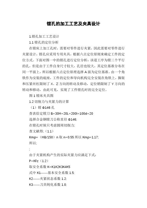
镗孔的加工工艺及夹具设计1.镗孔加工工艺设计1.1镗孔的定位分析在镗床上加工孔时,需要对零件进行夹紧,因此需要对零件进行夹紧设计,镗孔应采用专用夹具,根据六点定位原则来确定工件的定位方式。
下面对图一中的镗孔进行定位分析:该道工序为镗三个平行的孔,但是由于工件自身尺寸较大,孔径也较大,其定位基准分布在同一平面上,所以根据六点定位原理选择A面为定位基准。
由一个角铁作为安装的底座,工件的定位和导向机构完全安装在角铁上,脚架和压紧丝杠限制了X、Z方向的转动及移动,定位销限制了Y方向的转动和移动,由此可见,实现了工件镗孔时的完全定位。
图1镗床夹具图1.2切削力与夹紧力的计算(1)镗Φ146孔查表给定镗刀B=30H=20L=200I=100d=20选择合金钢镗刀公称直径Φ146;在镗孔时候只考虑圆周切削力;查文献得;(1.1)Kmp=(HB/150)n取n=0.55所以Kmp=1.17;所以;;由于夹紧机构产生的实际夹紧力应满足下式:P=KFz(1.2)取安全系数K=K1K2K3K4K5式中K1——基本安全系数1.5;K2——夹紧状态系数1.2;K3——刀具钝化系数1.0;K4——考虑夹紧动力稳定性系数1.0;K5——尽在有力矩企图使用回转时开考虑支撑面接触情况的系数1.0;所以得到K=K1K2K3K4K5=1.9,得到P=KFz=1.9X365.18=693.88N (2)镗Φ48孔选择高速钢镗刀公称直径Φ48;查表给定镗刀B=25H=30L=170I=80d=15在镗孔时候只考虑圆周切削力;查文献得;Kmp=(HB/150)n取n=0.55所以Kmp=1.17;所以;;由于夹紧机构产生的实际夹紧力应满足下式:P=KFz取安全系数K=K1K2K3K4K5式中K1——基本安全系数1.5;K2——夹紧状态系数1.2;K3——刀具钝化系数1.0;K4——考虑夹紧动力稳定性系数1.0;K5——尽在有力矩企图使用回转时开考虑支撑面接触情况的系数1.0;所以得到K=K1K2K3K4K5=1.9,得到P=KFz=1.9X223.2=424.08N <ol> 镗Φ80孔</ol>镗Φ80孔的计算过程与上边量孔的方法是一样的,就是选择高速钢镗刀公称直径Φ80的镗刀,最后计算结果为P=KFz=569.23N 根据上边的计算夹紧力不是很大,且夹具选择的种类为组合夹具,所以动力选择手动夹紧。
- 1、下载文档前请自行甄别文档内容的完整性,平台不提供额外的编辑、内容补充、找答案等附加服务。
- 2、"仅部分预览"的文档,不可在线预览部分如存在完整性等问题,可反馈申请退款(可完整预览的文档不适用该条件!)。
- 3、如文档侵犯您的权益,请联系客服反馈,我们会尽快为您处理(人工客服工作时间:9:00-18:30)。
胍 白 幽/ c& Acs e0
双 向 六 轴 镗 孔 机 附 属 工 艺 装 备 的设 计
上 海一纺机械有 限公 司 ( 00 1 杨培飞 2 05 )
化 ,将 工件的相关 尺寸分解为横 向 ( x向) 与上下方 向 ( z向 )2个方 向的尺寸 ( 见图 1 ,镗具设 计 的关键 就 )
是要解决 这个 问题 。
9
为了解 决工件镗 孔难 点 ,我 厂加强 工艺 自主创新 , 开发了镗孔专机 。整个专机 系统 ,除 了主机之外 ,还需 要按不 同的用途配置各种不 同类 型的工艺 装备 ,现统 称 之 为附属工艺装备 ,包括镗具 、电气控 制 、刀具 、冷却 润滑装置与 防漏装置等。附属工艺装 备作为专 机 的一个
图 3 定位垫块结构 图
1 工件 2 . .工作台 3 定位垫块 4 . .定位支座 5 镗具体 . 6 .镗刀 7 主轴箱 8 . .垫块 9 .电动机 1.滑台 1. O 1 床身
参磊 工冷 工 加
www. a m chf sf co . n ni . m c
! 笙! 塑_
维普资讯
在镗具设 计与制造 的过 程中需要做 到 以下 5 ,才 点 能攻 克镗 孔难关 。 乳 定位垫块的高度尺寸是系统积累误 差的综合 ,它
先将夹紧力作用点选在定位垫块上 ,再配之 以合 适的夹
紧元件 ,能保证工件可靠定 位 ,不会 引起 工件位移或 偏
度 不 大 于 00 r .3 m。 a
确定 ,就是对 6 ± f的控制 ,6 ± f尺寸准确性是 6 6
镗孔是否成功的关键 ,也是整个系统 ( 包括滑台、垫块 、
主轴箱 、镗刀 、 工件 、 镗具 与工作 台等 )设计的难 点。系
统 的积累误差最后反映到定位垫块的高度上 ( 见图3 。 )
Байду номын сангаас
转。在保证工件稳妥夹紧的前提下 ,采用 较少的夹 紧元 件 ,使夹紧变形尽可能小 ,工件受力 均匀 ,提高镗孔 精
度。本镗具仅使用两块 压板 ,夹 紧效果很好 。
的测量与计算非常重要,是工件上6 个孔的尺寸公差是 否满足设计要求的要点,精度控制在 005 m之内。 .0 m
h 镗具与工作台结合为一体后 ,定位支座上平 面与 . 工作台平面的平行度小于 005 m .0 m 。 C 定位支座上 平面与 6 . 根主轴 中心线 的平行 度小于
d 专机的综合制造精度必须在合 理范 围内 , . 保证 6 把镗刀的 中心线在 同一 平面内。
£工件镗孔前的综 合公差在合理 范围内。
辅助定位 、 夹紧作用。这样设计的优点是:
由图 3 可知 ,定位垫块的高度计算如下 :
4+ 5+L =L 8+厶 + 1 4 6 々+ 0+ () 1
理质量 。
2 C l6 一 dH
向尺寸 的调整 有赖于对刀 件 2 解决 ,用对 刀件 来
准确而迅速地找正 镗刀与 镗具相 对位置 ,控制工 件 2 一
c c ±A 的尺寸。一旦 镗具 到位 后 ,便将 其 牢牢地 锁 紧在 工作 台滑 台上 ,以保证 向尺寸 的一致性 。当 2 ±A 一c c 尺寸到位之后 ,2 一Ⅱ±A a与 2 6±A — b尺 寸加工难 点也
. ~\
1 三
图 2 镗具结构图
1 .镗具体 2 .对刀件 3 螺钉调节支座 4 . .托架 5 .顶尖 6 1 压块 7 、1. .定位键 8 .工件 9 .定位支座 1.定位垫块 O 1.定 位销 1.压板 2 3
零件之一 ,由下钳板与下钳板架结 合而成 ,两 端面对称 分布有 6个孔 ,孔的加工精度直接影 响到棉精 梳机 的梳
0 0 5 no . 0 t i o
受工件形 状 限制 ,定 位基 准 与 镗孔 处 之 间距 离较 大 ,支撑 刚性较差 , 外形结构就 像悬臂梁 一样 ,在切 削
力、工件 本身重力作用 下,可能发生 定位不稳 或镗孔 时 会振 动 ,因而需要考虑增设辅助支撑 。 本镗具在悬臂梁处安装 了两个托架 9 ( 见图 4) ,起
镗具结构见 图 2 ,它主要 由镗 具体 、定位 支座 、 定
位垫块 、定 位销 、压板 、托架 和对刀件 等组成 。 ① 定位基准 的选择 根 据 “ 点定 位原 则 ”取 工 六
件 的 面、钳唇 线与 面作 为定 位基 准 ,这样选 取基
准的优点是 :定位基准与设计基 准重合 ,能够减少 定位 误差 ,保证足够 的定位精度 ,镗具结构简单 。 ② 镗孔难点的解决 为 了解决镗孔难点先把问题简
L 8=L +L 一L 一L 5 6 7一 1 0
() 2
式中 L——床身高度,/ : 0r d " 60 m 4 a
— —
、
滑 台高度 , 5 30 m L : 2m
厶——主轴箱主轴 中心线 高度 与 垫块 高度 之 和 ,
, j √
.| .
1 0 l 1 1 2 1 3
重 要组成部分 ,是保证 工件 镗孔 获得 高精 度 、高 速度 、
高效率 、低成本 的工艺装备 。
j 岛 / 巾
卅 针
{ /‘ 删 r 一
什十 卜
l / ,
1 镗具的设计 .
( )工件简介 1 如图 l 所示 的工 件是 精梳机主关键
图 1 工 件简图
1 .下 钳板 架 2 .下 钳板
就随之解决 了。
( )镗具结构与工作原理 2
镗具是专机 镗孔时 ,用
另一个镗孔难点就是镗刀与工件在 z向相对位置 的
以准确地确定工件位置 ,并将其 牢固地夹 紧以接受 加工
的工艺装 备 。镗具 的综 合 制 造 精度 与 工件 2 一c±A 、 c 6 厂 f尺寸是否符合图样要求有 关。为 了保 证镗孔 质 —_±6 量 ,在镗具设计之前 ,工件必须满足下 钳板定 位面平 面