外文翻译(英文)
外文翻译 - 英文

The smart gridSmart grid is the grid intelligent (electric power), also known as the "grid" 2.0, it is based on the integration, high-speed bidirectional communication network, on the basis of through the use of advanced sensor and measuring technology, advanced equipme nt technology, the advancedcontrol method, and the application of advanced technology of decision support system, realize the power grid reliability, security, economic, efficient, environmental friendly and use the security target, its main features include self-healing, incentives and include user, against attacks, provide meet user requirements of power quality in the 21st century, allow all sorts of different power generation in the form of access, start the electric power market and asset optimizatio n run efficiently.The U.S. department of energy (doe) "the Grid of 2030" : a fully automated power transmission network, able to monitor and control each user and power Grid nodes, guarantee from power plants to end users among all the nodes in the whole process of transmission and distribution of information and energy bi-directional flow.China iot alliance between colleges: smart grid is made up of many parts, can be divided into:intelligent substation, intelligent power distribution network, intelli gent watt-hourmeter,intelligent interactive terminals, intelligent scheduling, smart appliances, intelligent building electricity, smart city power grid, smart power generation system, the new type of energy storage system.Now a part of it to do a simple i ntroduction. European technology BBS: an integration of all users connected to the power grid all the behavior of the power transmission network, to provide sustained and effective economic and security of power.Chinese academy of sciences, institute of electrical: smart grid is including all kinds of power generation equipment, power transmission and distribution network, power equipment and storage equipment, on the basis of the physical power grid will be modern advanced sensor measurement technology, network technology, communicationtechnology, computing technology, automationand intelligent control technology and physical grid highly integrated to form a new type of power grid, it can realize the observable (all the state of the equipment can monitor grid), can be controlled (able to control the power grid all the state of the equipment), fully automated (adaptive and self-healing) and system integrated optimization balance (power generation, transmission and distribution, and the optimization of the balance between electricity), so that the power system is more clean, efficient, safe and reliable.American electric power research institute: IntelliGrid is a composed of numerous automation system of power transmission and distribution power system, in a coordinated, effective and reliable way to achieve all of the power grid operation: have self-healing function;Rapid response to the electric power market and enterprise business requirements;Intelligent communication architecture, realizes the real-time, security, and flexible information flow, to provide users with reliable, economic power services. State grid electric power research institute, China: on the basis of the physical power grid (China's smart grid is based on high voltage network backbone network frame, different grid voltage level based on the coordinated development of strong power grid), the modern advanced sensor measurement technology, communication technology, information technology, computer technology and control technology and the physical power grid highly integrated to form a new type of power grid.It to fully meet user demand for electricity and optimize the allocation of resources, guarantee the safety, reliability and economy of power supply, meet environmental constraints, ens ure the quality of electric energy, to adapt to the development of power market, for the purpose of implementing the user reliable, economic, clean and interactive power supply and value-added services.BackgroundStrong smart grid development in the wor ld is still in its infancy, without a common precisely defined, its technology can be roughly divided into four areas: advanced Measurement system, advanced distribution operation, advanced transmission operation and advanced asset management.Advanced meas urement system main function is authorized to the user, make the system to establish a connection with load, enabling users to support the operationof the power grid;Advanced core distribution operation is an online real-time decision command, goal is to disaster prevention and control, realizing large cascading failure prevention;Advanced transmission operation main role is to emphasize congestion ma nagement and reduce the risk of the large-scale railway;Advanced asset management is installed in the system can provide the system parameters and equipments (assets) "health" condition of advanced sensor, and thereal-time information collected by integrat ion and resource management, modeling and simulation process, improve the operation and efficiency of power grid.The smart grid is an important application of Internet of things, and published in the journal of computer smart grid information system archit ecture research is carried on the detailed discussion on this, and the architecture of the smart grid information system are analyzed.The market shareThe establishment of the smart grid is a huge historical works.At present many complicated smart grid project is underway, but the gap is still great.For the provider of the smart grid technology, promote the development of facing the challenges of the distribution network system i s upgrading, automation and power distribution substation transportation, smart grid network and intelligent instruments.According to the latest report of parker investigators, smart grid technology market will increase from $2012 in 33 billion to $2020 in 73 billion, eight years, the market accumulated up to $494 billion.China smart grid industry market foresight and investment forward-looking strategic planning analysis, points out that in our country will be built during the "twelfth five-year""three vertical and three horizontal and one ring" of uhv ac lines, and 11 back to u hv dc transmission project construction, investment of 300 billion yuan.Although during the period of "much starker choices-and graver consequences-in" investment slowed slightly, the investment is 250 billion yuan.By 2015, a wide range of national power grid, long distance transmission capacity will reach 250 million kilowatts, power transmission of 1.15 trillion KWH per year, to support the new 145 million kilowatts of clean energy generation given and sent out, can satisfy the demand of morethan 1 million electric cars, a grid resource configuration optimization ability, economic efficiency, safety and intelligent levels will be fully promoted.The abroad application of analysisIn terms of power grid development foundation, national electricity dema nd tends to be saturated, the grid after years of rapid development, architecture tends to be stable, mature, have a more abundant supply of electric power transmission and distribution capacity.Germany has "E - Energy plan, a total investment of 140 million euros, from 2009 to 2012, four years, six sites across the country to the smart grid demonstration experiment.At the same time also for wind power and electric car empirical experiments, testing and management of power consumption of the Internet.Big companies such as Germany's Siemens, SAP and Swiss ABB are involved in this plan.To smart grid Siemens 2014 annual market scale will reach 30 billion euros, and plans to take a 20% market share, make sure order for 6 billion euros a year.The advanced nat ureCompared with the existing grid, smart grid, reflects the power flow, information flow and business flow marked characteristics of highly integration, its advancement and advantage mainly displays in:(1) has a strong foundation of grid system and te chnical support system, able to withstand all kinds of external disturbance and attacks, can adapt to large-scale clean energy and renewable energy access, strong sex of grid reinforced and ascend.(2) the information technology, sensor technology, automatic control technology organic combination with power grid infrastructure, a panoramic view of available power grid information, timely detection, foresee the possibility of failure.Fault occurs, the grid can be quickly isolate fault,realize self recovery,to avoid the occurrence of blackouts.(3) flexible ac/dc transmission, mesh factory coordination, intelligent scheduling, power storage, and distribution automation technology widespread application, makes the control of power grid operation more flexibl e,economic, and can adapt to a large number of distributed power supply, power grid and electric vehicle charging and discharging facility access.(4) communication, information, and the integrated use of modern management technology, will greatly improve the efficiency of power equipment, and reduce the loss of electrical power, making the operation of power grid is more economic and efficient.(5) the height of the real-time and non real-time information integration, sharing and utilization, to run the show management comprehensive, complete and fine grid operation state diagram, at the same time can provide decision support, control scheme and the corresponding response plans.(6) to establish a two-way interactive service mode, users can real-time understand the status of the power supply ability, power quality, price and power outage information, reasonable arrangement of electric equipment use;The electric power enterprise can obtain the user's electricity information in detail, to provide more value-added services.developmentaltrend"Twelfth five-year" period, the state grid will invest 500 billion yuan to build the connection of large ene rgy base and center of the "three horizontal three longitudinal" main load of ultra high voltage backbone network frame and 13 back to long branch, engineering, to form the core of the world first-class strong smart grid."Strong smart grid technology standards promulgated by the state grid system planning", has been clear about the strong smart grid technology standards roadmap, is the world's first used to guide the development of smart grid technology guiding standards.SGC planning is to built 2015 basic information, automation, interaction characteristics of strong smart grid, formed in north China, central China, east China, for the end to the northwest and northeast power grid for sending the three synchronous power grid, the grid resource allocati on ability, economic efficiency and safety level, technology level and improve intelligent level.(1) the smart grid is the inevitable developing trend ofpower grid technology.Such as communication, computer, automation technology has extensive applicati on in the power grid, and organic combination with traditional electric power technology, and greatly improve the intelligent level of the power grid.Sensor technology and information technology application in the power grid, the system state analysis and auxiliary decision provides the technical support, make it possible to grid self-healing.Scheduling technology, automation technology and the mature development of flexible transmission technology, for the development and utilization of renewable energy an d distributed power supply provides the basic guarantee.The improvement of the communication network and the popularization and application of user information collection technology, promote the two-way interaction with users of the grid.With the further development of various new technologies, application and highly integrated with the physical power grid, smart grid arises at the historic moment.(2) the development of smart grid is the inevitable choice of social and economic development.In order to ach ieve the development of clean energy, transport and given power grid must increase its flexibility and compatibility.To withstand the increasingly frequent natural disasters and interference, intelligent power grid must rely on means to improve its securit y defense andself-healing ability.In order to reduce operating costs, promote energy conservation and emissions reduction, power grid operation must be more economic and efficient, at the same time must to intelligent control of electric equipment, reduce electricity consumption as much as possible.Distributed generation and energy storage technology and the rapid development of electric cars, has changed the traditional mode of power supply, led power flow, information flow, business flow constantly fusion, in order to satisfy the demands of increasingly diverse users.PlanJapan plans to all the popularity of smart grid in 2030, officer of the people at the same time to promote the construction of overseas integrated smart grid.In the field of battery, Japanese firms' global market share goal is to strive to reach 50%, with about 10 trillion yen in the market.Japan's trade ministry has set up a "about the next generation of energy systems international standardizationresearch institute", the japan-american established in Okinawa and Hawaii for smart grid experimental project [6].Learns in the itu, in 2020 China will be built in high power grid with north China, east China, China as the center, northeast, northwest 750 kv uhv power grid as the sending, connecting each big coal base, large hydropower bases, big base for nuclear power, renewable energy base, the coordinated development of various grid strong smart grid.In north China, east China, China high voltage synchronous ZhuWangJia six "five longitudi nal and transverse" grid formation.The direction ofIn the green energy saving consciousness, driven by the smart grid to become the world's countries to develop a focus areas.The smart grid is the electric power network, is a self-healing, let consum ers to actively participate in, can recover from attacks and natural disasters in time, to accommodate all power generation and energy storage, can accept the new product, service and market, optimize asset utilization and operation efficiency, provide qua lity of power supply for digital economy.Smart grid based on integrated, high-speed bidirectional communication network foundation, aims to use advanced sensor and measuring technology, advanced equipment, technology and advanced control methods, and adv anced technology of decision support system, realize the power grid reliability, security, economic, efficient, environmental friendly, and the use of safe run efficiently.Its development is a gradual progressive evolution, is a radical change, is the product of the coordinated development of new and existing technologies, in ad dition to the network and smart meters also included the wider range.Grid construction in high voltage network backbone network frame, all levels of the coordinated development, informatization, automation, interaction into the characteristics of strong smart grid, improve network security, economy, adaptability and interactivity, strength is the foundation, intelligence is the key.meaningIts significance is embodied in the foll owing aspects:(1) has the strong ability of resources optimization allocation.After the completion of the smart grid in China, will implement the big water and electricity, coal, nuclear power, large-scale renewable energy across regions, long distance, large capacity, low loss, high efficiency, regional power exchange capacity improved significantly.(2) have a higher level of safe and stable operation.Grid stability and power supply reliability will be improved, the safety of the power grid close coord ination between all levels of line, have theability to against sudden events and serious fault, can effectively avoid the happening of a wide range of chain failure, improve power supply reliability, reduce the power loss.(3) to adapt and promote the dev elopment of clean energy.Grid will have wind turbines power prediction and dynamic modeling, low voltage across, and active reactive power control and regular units quickly adjust control mechanism, combined with the application of large capacity storage technology, the operation control of the clean energy interconnection capacity will significantly increased, and make clean energy the more economical, efficient and reliable way of energy supply.(4)implementing highly intelligent power grid scheduling.Co mpleted vertical integration, horizontal well versed in the smart grid scheduling technology support system, realize the grid online intelligent analysis, early warning and decision-making, and all kinds of new transmission technology and equipment of effi cient control and lean control of ac/dc hybrid power grid.(5)can satisfy the demands of electric cars and other new type electric power user services.Would be a perfect electric vehicle charging and discharging supporting infrastructure network, can meet the needs of the development of the electric car industry, to meet the needs of users, realize high interaction of electric vehicles and power grid.(6) realize high utilization and whole grid assets life cycle management.Can realize electric grid system of the whole life cycle management plan.Through smart grid scheduling and demand side management, power grid assets utilization hours, power grid assets efficiency improvedsignificantly.(7) to realize power convenient interaction between the user and the grid.Will form a smart electricity interactive platform, improving the demand side management, to provide users with high-quality electric power service.At the same time, the comprehensive utilization of the grid can be distributed power supply, intelli gent watt-hour meter, time-sharing electricity price policy and the electric vehicle charging and discharging mechanism, effectively balance electric load, reduce the peak valley load difference, reduce the power grid and power construction costs.(8)grid management informatization and the lean.Covering power grid will each link of communication network system, realize the power grid operation maintenance integrated regulation, data management, information grid spatial information services, and production and scheduling application integration, and other functions, to realize all-sided management informatization and the lean.(9) grid infrastructure of value-added service potential into full play.In power at the same time, the national strategy of "triple play" of services, to provide users with community advertising, network television, voice and other integrated services, such as water supply, heating, gas industry informatization, interactive platform support, expand the range of value-added services and improve the grid infrastructure and capacity, vigorously promote the development of smart city.(10)Gridto promote the rapid development of related industries.Electric power industry belongsto the capital-intensive and technology-intensive industry, has the characteristics of huge investment, long industrial chain.Construction of smart grid, which is beneficial to promote equipment manufacturing information and communication industry technology upgrade, for our country to occupy the high ground to lay the foundation in the field of electric power equipment manufacturing.Important significanceLife is convenientThe construction of strong smart grid, will promote the development of intelligent community, smart city, improve people's quality of life.(1) to make life more convenient.Home intelligent power system can not onlyrealize the real-time control of intelligent home appliances such as air conditioning, water heater and remote control;And can provide telecommunication network, Internet, radio and television network access services;Through intelligent watt-hour meter will also be able to achieve au tomatic meter reading and automatic transfer fee, and other functions.(2) to make life more low carbon.Smart grid can access to the small family unit such as wind power and photovoltaic roof, pushing forward the large-scale application of electric cars, so as to raise the proportion of clean energy consumption, reduce the pollution of the city.(3) to make life more economical.The smart grid can promote power user role transformation, both electricity and sell electricity twofold properties;To build a family for the user electricity integrated services platform, to help users choose the way of electricity, save energy, reduce the energy expense.Produce benefitThe development of a strong smart grid, the grid function gradually extended to promote the optim al allocation of energy resources, guarantee the safe and stable operation of power system, providing multiple open power service, promote the development of strategic emerging industries, and many other aspects.As China's important energy delivery and configuration platform, strong and smart grid from the investment construction to the operation of production process will be for the national economic development, energy production and use, environmental protection bring great benefits.(1)in power system.Can save system effective capacity;Reducing the system total power generation fuel cost;Improving the efficiency of grid equipment, reduce construction investment;Ascension grid transmission efficiency, reduce the line loss.(2)in terms of power customers.Can realize the bidirectional interaction, to provide convenient services;Improving terminal energy efficiency, save power consumption;To improve power supply reliability, and improve power quality.(3) in the aspect of energy saving and environment.Can improve the efficiency of energy utilization, energy conservation and emissions reduction benefit.To promote clean energy development, realize the alternative reductionbenefits;Promote the overall utilization of land resources, saving land usage.(4) other aspects.Can promote the economic development, jobs;To ensure the safety of energy supply;Coal for power transmission and improve the efficiency of energy conversion, reducing the transportation pressure.Propulsion system(1) can effectively improve t he security of power system and power supply e of strong smart grid "self-healing" function, can accurately and quickly isolate the fault components, and in the case of less manual intervention make the system quickly returned to normal, so as to improve the security and reliability of power supply system.(2) the power grid to realize the sustainable development.Strong smart grid technology innovation can promote the power grid construction, implementation technology, equipment, operation an d management of all aspects of ascension, to adapt to the electric power market demand, promote the scientific and sustainable development of power grid.(3) reduce the effective ing the power load characteristics in different regions of the ch aracteristics of big differences through the unification of the intelligent dispatching, the peakand peak shaving, such as networking benefit;At the same time through the time-sharing electricity price mechanism, and guide customers low power, reduce the peak load, so as to reduce the effective capacity.(4) to reduce the system power generation fuel costs.Construction of strong smart grid, which can meet the intensive development of coal base, optimization of power distribution in our country, thereby red ucing fuel transportation cost;At the same time, by reducing the peak valley load difference, can improve the efficiency of thermal power unit, reduce the coal consumption, reduce the cost.(5)improve the utilization efficiency of grid equipment.First of all, by improving the power load curve, reduce the peak valley is poor, improve the utilization efficiency of grid equipment;Second, by self diagnosis, extend the life of the grid infrastructure.(6) reduce the line loss.On the important basis of uhv transmission technology of strong smart grid, will greatly reduce the loss rate in the electric power transmission;Intelligent scheduling system, flexible transmission technology and real-time two-way interaction with customers, can optimize the tide distribut ion, reducing line loss;At the same time, the construction and application of distributed power supply, also reduce the network loss of power transmission over a long distance.Allocation of resourcesEnergy resources and energy demand in the reverse distribution in our country, more than 80% of the coal, water power and wind power resource distribution in the west, north, and more than 75% of the energy demand is concentrated in the eastern and central regions.Energy resources and energy demand unbalance d distribution of basic national conditions, demand of energy needs to be implemented nationwide resource optimizing configuration.The construction of strong smart grid, for optimal allocation of energy resources provides a good platform.Strong smart grid is completed, will form a strong structure and sending by the end of the power grid power grid, power capacity significantly strengthened, and the formation of the intensity, stiffness of uhv power transmission network, realize the big water and electricit y, coal, nuclear power, large-scale renewable energy across regions, long distance, large capacity, low loss, high efficiency transport capacity significantly increased power a wide range of energy resources optimization.Energy developmentThe development and utilization of clean energy such as wind power and solar energy to produce electricity is given priority to, in the form of the construction of strong smart grid can significantly improve the grid's ability to access, given and adjust clean energy, vigorously promote the development of clean energy.(1) smart grid, the application of advanced control technology and energy storage technology, perfect the grid-connected clean energy technology standards, improve the clean energy acceptance ability.Clean energy base, (2) the smart grid, rational planning of large-scale space truss structure and sending the power structure, application of uhv, flexible transmission technology, meet the requirements of the large-scale clean energy electricitytransmission.(3) the smart grid for large-scale intermittent clean energy to carry on the reasonable and economic operation, improve the operation performance of clean energy production.(4) intelligent with electric equipment, can achieve acceptance and coordinated cont rol of distributed energy, realize the friendly interaction with the user, the user to enjoy the advantages of new energy power.Energy conservation and emissions reductionStrong smart grid construction to promote energy conservation and emissions reduc tion,development of low carbon economy is of great significance: (1) to support large-scale clean energy unit net, accelerate the development of clean energy, promote our country the optimization of energy structure adjustment;(2) to guide users reasonable arrangement of electricity, reducing peak load, stable thermal power unit output, reduce power generation coal consumption;(3) promote ultra-high voltage, flexible transmission, promotion and application of advanced technology such as economic operation, reduce the transmission loss, improve power grid operation efficiency;(4) to realize the power grid to interact with users effectively, promote intelligent power technology, improve the efficiency of electricity;(5) to promote the electric car of large-scale application, promote the development of low-carbon economy, achieve emission reduction benefits.There are three milestones of the concept of smart grid development:The first is 2006, the United States "smart grid" put forward by the IBM solution.IBM smart grid is mainly to solve, improve reliability and safety of power grid from its release in China, the construction of the smart grid operations management innovation - the new train of thought on the development of China's power "the white paper can be seen that the scheme provides a larger framework, through to the electric power production, transmission, the optimization of all aspects of retail management, for the relevant enterprises to improve operation efficiency and reliability, reduce cost dep icts a blueprint.IBM is a marketing strategy.The second is the energy plan put forward by the Obama took office, in addition to the published plan, the United States will also focus on cost $120 billion a year circuit。
外文翻译中英文对照

Strengths优势All these private sector banks hold strong position on CRM part, they have professional, dedicated and well-trained employees.所以这些私人银行在客户管理部分都持支持态度,他们拥有专业的、细致的、训练有素的员工。
Private sector banks offer a wide range of banking and financial products and financial services to corporate and retail customers through a variety of delivery channels such as ATMs, Internet-banking, mobile-banking, etc. 私有银行通过许多传递通道(如自动取款机、网上银行、手机银行等)提供大范围的银行和金融产品、金融服务进行合作并向客户零售。
The area could be Investment management banking, life and non-life insurance, venture capital and asset management, retail loans such as home loans, personal loans, educational loans, car loans, consumer durable loans, credit cards, etc. 涉及的领域包括投资管理银行、生命和非生命保险、风险投资与资产管理、零售贷款(如家庭贷款、个人贷款、教育贷款、汽车贷款、耐用消费品贷款、信用卡等)。
Private sector banks focus on customization of products that are designed to meet the specific needs of customers. 私人银行主要致力于为一些特殊需求的客户进行设计和产品定制。
毕业设计外文翻译_英文版
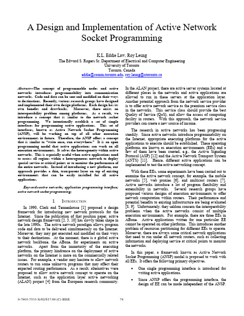
A Design and Implementation of Active NetworkSocket ProgrammingK.L. Eddie Law, Roy LeungThe Edward S. Rogers Sr. Department of Electrical and Computer EngineeringUniversity of TorontoToronto, Canadaeddie@, roy.leung@utoronto.caAbstract—The concept of programmable nodes and active networks introduces programmability into communication networks. Code and data can be sent and modified on their ways to destinations. Recently, various research groups have designed and implemented their own design platforms. Each design has its own benefits and drawbacks. Moreover, there exists an interoperability problem among platforms. As a result, we introduce a concept that is similar to the network socket programming. We intentionally establish a set of simple interfaces for programming active applications. This set of interfaces, known as Active Network Socket Programming (ANSP), will be working on top of all other execution environments in future. Therefore, the ANSP offers a concept that is similar to “write once, run everywhere.” It is an open programming model that active applications can work on all execution environments. It solves the heterogeneity within active networks. This is especially useful when active applications need to access all regions within a heterogeneous network to deploy special service at critical points or to monitor the performance of the entire networks. Instead of introducing a new platform, our approach provides a thin, transparent layer on top of existing environments that can be easily installed for all active applications.Keywords-active networks; application programming interface; active network socket programming;I. I NTRODUCTIONIn 1990, Clark and Tennenhouse [1] proposed a design framework for introducing new network protocols for the Internet. Since the publication of that position paper, active network design framework [2, 3, 10] has slowly taken shape in the late 1990s. The active network paradigm allows program code and data to be delivered simultaneously on the Internet. Moreover, they may get executed and modified on their ways to their destinations. At the moment, there is a global active network backbone, the ABone, for experiments on active networks. Apart from the immaturity of the executing platform, the primary hindrance on the deployment of active networks on the Internet is more on the commercially related issues. For example, a vendor may hesitate to allow network routers to run some unknown programs that may affect their expected routing performance. As a result, alternatives were proposed to allow active network concept to operate on the Internet, such as the application layer active networking (ALAN) project [4] from the European research community. In the ALAN project, there are active server systems located at different places in the networks and active applications are allowed to run in these servers at the application layer. Another potential approach from the network service provider is to offer active network service as the premium service class in the networks. This service class should provide the best Quality of Service (QoS), and allow the access of computing facility in routers. With this approach, the network service providers can create a new source of income.The research in active networks has been progressing steadily. Since active networks introduce programmability on the Internet, appropriate executing platforms for the active applications to execute should be established. These operating platforms are known as execution environments (EEs) and a few of them have been created, e.g., the Active Signaling Protocol (ASP) [12] and the Active Network Transport System (ANTS) [11]. Hence, different active applications can be implemented to test the active networking concept.With these EEs, some experiments have been carried out to examine the active network concept, for example, the mobile networks [5], web proxies [6], and multicast routers [7]. Active networks introduce a lot of program flexibility and extensibility in networks. Several research groups have proposed various designs of execution environments to offer network computation within routers. Their performance and potential benefits to existing infrastructure are being evaluated [8, 9]. Unfortunately, they seldom concern the interoperability problems when the active networks consist of multiple execution environments. For example, there are three EEs in ABone. Active applications written for one particular EE cannot be operated on other platforms. This introduces another problem of resources partitioning for different EEs to operate. Moreover, there are always some critical network applications that need to run under all network routers, such as collecting information and deploying service at critical points to monitor the networks.In this paper, a framework known as Active Network Socket Programming (ANSP) model is proposed to work with all EEs. It offers the following primary objectives.• One single programming interface is introduced for writing active applications.• Since ANSP offers the programming interface, the design of EE can be made independent of the ANSP.This enables a transparency in developing andenhancing future execution environments.• ANSP addresses the interoperability issues among different execution environments.• Through the design of ANSP, the pros and cons of different EEs will be gained. This may help design abetter EE with improved performance in future.The primary objective of the ANSP is to enable all active applications that are written in ANSP can operate in the ABone testbed . While the proposed ANSP framework is essential in unifying the network environments, we believe that the availability of different environments is beneficial in the development of a better execution environment in future. ANSP is not intended to replace all existing environments, but to enable the studies of new network services which are orthogonal to the designs of execution environments. Therefore, ANSP is designed to be a thin and transparent layer on top of all execution environments. Currently, its deployment relies on automatic code loading with the underlying environments. As a result, the deployment of ANSP at a router is optional and does not require any change to the execution environments.II. D ESIGN I SSUES ON ANSPThe ANSP unifies existing programming interfaces among all EEs. Conceptually, the design of ANSP is similar to the middleware design that offers proper translation mechanisms to different EEs. The provisioning of a unified interface is only one part of the whole ANSP platform. There are many other issues that need to be considered. Apart from translating a set of programming interfaces to other executable calls in different EEs, there are other design issues that should be covered, e.g., • a unified thread library handles thread operations regardless of the thread libraries used in the EEs;• a global soft-store allows information sharing among capsules that may execute over different environmentsat a given router;• a unified addressing scheme used across different environments; more importantly, a routing informationexchange mechanism should be designed across EEs toobtain a global view of the unified networks;• a programming model that should be independent to any programming languages in active networks;• and finally, a translation mechanism to hide the heterogeneity of capsule header structures.A. Heterogeneity in programming modelEach execution environment provides various abstractions for its services and resources in the form of program calls. The model consists of a set of well-defined components, each of them has its own programming interfaces. For the abstractions, capsule-based programming model [10] is the most popular design in active networks. It is used in ANTS [11] and ASP [12], and they are being supported in ABone. Although they are developed based on the same capsule model, their respective components and interfaces are different. Therefore, programs written in one EE cannot run in anther EE. The conceptual views of the programming models in ANTS and ASP are shown in Figure 1.There are three distinct components in ANTS: application, capsule, and execution environment. There exist user interfaces for the active applications at only the source and destination routers. Then the users can specify their customized actions to the networks. According to the program function, the applications send one or more capsules to carry out the operations. Both applications and capsules operate on top of an execution environment that exports an interface to its internal programming resources. Capsule executes its program at each router it has visited. When it arrives at its destination, the application at destination may either reply it with another capsule or presents this arrival event to the user. One drawback with ANTS is that it only allows “bootstrap” application.Figure 1. Programming Models in ASP and ANTS.In contrast, ASP does not limit its users to run “bootstrap” applications. Its program interfaces are different from ANTS, but there are also has three components in ASP: application client, environment, and AAContext. The application client can run on active or non-active host. It can start an active application by simply sending a request message to the EE. The client presents information to users and allows its users to trigger actions at a nearby active router. AAContext is the core of the network service and its specification is divided into two parts. One part specifies its actions at its source and destination routers. Its role is similar to that of the application in ANTS, except that it does not provide a direct interface with the user. The other part defines its actions when it runs inside the active networks and it is similar to the functional behaviors of a capsule in ANTS.In order to deal with the heterogeneity of these two models, ANSP needs to introduce a new set of programming interfaces and map its interfaces and execution model to those within the routers’ EEs.B. Unified Thread LibraryEach execution environment must ensure the isolation of instance executions, so they do not affect each other or accessThe authors appreciate the Nortel Institute for Telecommunications (NIT) at the University of Toronto to allow them to access the computing facilitiesothers’ information. There are various ways to enforce the access control. One simple way is to have one virtual machine for one instance of active applications. This relies on the security design in the virtual machines to isolate services. ANTS is one example that is using this method. Nevertheless, the use of multiple virtual machines requires relatively large amount of resources and may be inefficient in some cases. Therefore, certain environments, such as ASP, allow network services to run within a virtual machine but restrict the use of their services to a limited set of libraries in their packages. For instance, ASP provides its thread library to enforce access control. Because of the differences in these types of thread mechanism, ANSP devises a new thread library to allow uniform accesses to different thread mechanisms.C. Soft-StoreSoft-store allows capsule to insert and retrieve information at a router, thus allowing more than one capsules to exchange information within a network. However, problem arises when a network service can execute under different environments within a router. The problem occurs especially when a network service inserts its soft-store information in one environment and retrieves its data at a later time in another environment at the same router. Due to the fact that execution environments are not allowed to exchange information, the network service cannot retrieve its previous data. Therefore, our ANSP framework needs to take into account of this problem and provides soft-store mechanism that allows universal access of its data at each router.D. Global View of a Unified NetworkWhen an active application is written with ANSP, it can execute on different environment seamlessly. The previously smaller and partitioned networks based on different EEs can now be merging into one large active network. It is then necessary to advise the network topology across the networks. However, different execution environments have different addressing schemes and proprietary routing protocols. In order to merge these partitions together, ANSP must provide a new unified addressing scheme. This new scheme should be interpretable by any environments through appropriate translations with the ANSP. Upon defining the new addressing scheme, a new routing protocol should be designed to operate among environments to exchange topology information. This allows each environment in a network to have a complete view of its network topology.E. Language-Independent ModelExecution environment can be programmed in any programming language. One of the most commonly used languages is Java [13] due to its dynamic code loading capability. In fact, both ANTS and ASP are developed in Java. Nevertheless, the active network architecture shown in Figure 2 does not restrict the use of additional environments that are developed in other languages. For instance, the active network daemon, anted, in Abone provides a workspace to execute multiple execution environments within a router. PLAN, for example, is implemented in Ocaml that will be deployable on ABone in future. Although the current active network is designed to deploy multiple environments that can be in any programming languages, there lacks the tool to allow active applications to run seamlessly upon these environments. Hence, one of the issues that ANSP needs to address is to design a programming model that can work with different programming languages. Although our current prototype only considers ANTS and ASP in its design, PLAN will be the next target to address the programming language issue and to improve the design of ANSP.Figure 2. ANSP Framework Model.F. Heterogeneity of Capsule Header StructureThe structures of the capsule headers are different in different EEs. They carries capsule-related information, for example, the capsule types, sources and destinations. This information is important when certain decision needs to be made within its target environment. A unified model should allow its program code to be executed on different environments. However, the capsule header prevents different environments to interpret its information successfully. Therefore, ANSP should carry out appropriate translation to the header information before the target environment receives this capsule.III. ANSP P ROGRAMMING M ODELWe have outlined the design issues encountered with the ANSP. In the following, the design of the programming model in ANSP will be discussed. This proposed framework provides a set of unified programming interfaces that allows active applications to work on all execution environments. The framework is shown in Figure 2. It is composed of two layers integrated within the active network architecture. These two layers can operate independently without the other layer. The upper layer provides a unified programming model to active applications. The lower layer provides appropriate translation procedure to the ANSP applications when it is processed by different environments. This service is necessary because each environment has its own header definition.The ANSP framework provides a set of programming calls which are abstractions of ANSP services and resources. A capsule-based model is used for ANSP, and it is currently extended to map to other capsule-based models used in ANTSand ASP. The mapping possibility to other models remains as our future works. Hence, the mapping technique in ANSP allows any ANSP applications to access the same programming resources in different environments through a single set of interfaces. The mapping has to be done in a consistent and transparent manner. Therefore, the ANSP appears as an execution environment that provides a complete set of functionalities to active applications. While in fact, it is an overlay structure that makes use of the services provided from the underlying environments. In the following, the high-level functional descriptions of the ANSP model are described. Then, the implementations will be discussed. The ANSP programming model is based upon the interactions between four components: application client , application stub , capsule , and active service base.Figure 3. Information Flow with the ANSP.•Application Client : In a typical scenario, an active application requires some means to present information to its users, e.g., the state of the networks. A graphical user interface (GUI) is designed to operate with the application client if the ANSP runs on a non-active host.•Application Stub : When an application starts, it activates the application client to create a new instance of application stub at its near-by active node. There are two responsibilities for the application stub. One of them is to receive users’ instructions from the application client. Another one is to receive incoming capsules from networks and to perform appropriate actions. Typically, there are two types of actions, thatare, to reply or relay in capsules through the networks, or to notify the users regarding the incoming capsule. •Capsule : An active application may contain several capsule types. Each of them carries program code (also referred to as forwarding routine). Since the application defines a protocol to specify the interactions among capsules as well as the application stubs. Every capsule executes its forwarding routine at each router it visits along the path between the source and destination.•Active Service Base : An active service base is designed to export routers’ environments’ services and execute program calls from application stubs and capsules from different EEs. The base is loaded automatically at each router whenever a capsule arrives.The interactions among components within ANSP are shown in Figure 3. The designs of some key components in the ANSP will be discussed in the following subsections. A. Capsule (ANSPCapsule)ANSPXdr decode () ANSPXdr encode () int length ()Boolean execute ()New types of capsule are created by extending the abstract class ANSPCapsule . New extensions are required to define their own forwarding routines as well as their serialization procedures. These methods are indicated below:The execution of a capsule in ANSP is listed below. It is similar to the process in ANTS.1. A capsule is in serial binary representation before it issent to the network. When an active router receives a byte sequence, it invokes decode() to convert the sequence into a capsule. 2. The router invokes the forwarding routine of thecapsule, execute(). 3. When the capsule has finished its job and forwardsitself to its next hop by calling send(), this call implicitly invokes encode() to convert the capsule into a new serial byte representation. length() isused inside the call of encode() to determine the length of the resulting byte sequence. ANSP provides a XDR library called ANSPXdr to ease the jobs of encoding and decoding.B. Active Service Base (ANSPBase)In an active node, the Active Service Base provides a unified interface to export the available resources in EEs for the rest of the ANSP components. The services may include thread management, node query, and soft-store operation, as shown in Table 1.TABLE I. ACTIVE SERVICE BASE FUNCTION CALLSFunction Definition Descriptionboolean send (Capsule, Address) Transmit a capsule towards its destination using the routing table of theunderlying environment.ANSPAddress getLocalHost () Return address of the local host as an ANSPAddress structure. This isuseful when a capsule wants to check its current location.boolean isLocal (ANSPAddress) Return true if its input argument matches the local host’s address andreturn false otherwise.createThread () Create a new thread that is a class ofANSPThreadInterface (discussed later in Section VIA “Unified Thread Abstraction”).putSStore (key, Object) Object getSStore (key) removeSStore (key)The soft-store operations are provided by putSStore(), getSSTore(), and removeSStore(), and they put, retrieve, and remove data respectively. forName (PathName) Supported in ANSP to retrieve a classobject corresponding to the given path name in its argument. This code retrieval may rely on the code loading mechanism in the environment whennecessary.C. Application Client (ANSPClient)boolean start (args[])boolean start (args[],runningEEs) boolean start (args[],startClient)boolean start (args[],startClient, runningEE)Application Client is an interface between users and the nearby active source router. It does the following responsibilities.1. Code registration: It may be necessary to specify thelocation and name of the application code in some execution environments, e.g., ANTS. 2. Application initialization: It includes selecting anexecution environment to execute the application among those are available at the source router. Each active application can create an application client instance by extending the abstract class, ANSPClient . The extension inherits a method, start(), to automatically handle both the registration and initialization processes. All overloaded versions of start() accept a list of arguments, args , that are passed to the application stub during its initialization. An optional argument called runningEEs allows an application client to select a particular set of environment variables, specified by a list of standardized numerical environment ID, the ANEP ID, to perform code registration. If this argument is not specified, the default setting can only include ANTS and ASP. D. Application Stub (ANSPApplication)receive (ANSPCapsule)Application stubs reside at the source and destination routers to initialize the ANSP application after the application clients complete the initialization and registration processes. It is responsible for receiving and serving capsules from the networks as well as actions requested from the clients. A new instance is created by extending the application client abstract class, ANSPApplication . This extension includes the definition of a handling routine called receive(), which is invoked when a stub receives a new capsule.IV. ANSP E XAMPLE : T RACE -R OUTEA testbed has been created to verify the design correctnessof ANSP in heterogeneous environments. There are three types of router setting on this testbed:1. Router that contains ANTS and a ANSP daemonrunning on behalf of ASP; 2. Router that contains ASP and a ANSP daemon thatruns on behalf of ANTS; 3. Router that contains both ASP and ANTS.The prototype is written in Java [11] with a traceroute testing program. The program records the execution environments of all intermediate routers that it has visited between the source and destination. It also measures the RTT between them. Figure 4 shows the GUI from the application client, and it finds three execution environments along the path: ASP, ANTS, and ASP. The execution sequence of the traceroute program is shown in Figure 5.Figure 4. The GUI for the TRACEROUTE Program.The TraceCapsule program code is created byextending the ANSPCapsule abstract class. When execute() starts, it checks the Boolean value of returning to determine if it is returning from the destination. It is set to true if TraceCapsule is traveling back to the source router; otherwise it is false . When traveling towards the destination, TraceCapsule keeps track of the environments and addresses of the routers it has visited in two arrays, path and trace , respectively. When it arrives at a new router, it calls addHop() to append the router address and its environment to these two arrays. When it finally arrives at the destination, it sets returning to false and forwards itself back to the source by calling send().When it returns to source, it invokes deliverToApp() to deliver itself to the application stub that has been running at the source. TraceCapsule carries information in its data field through the networks by executing encode() and decode(), which encapsulates and de-capsulates its data using External Data Representation (XDR) respectively. The syntax of ANSP XDR follows the syntax of XDR library from ANTS. length() in TraceCapsule returns the data length, or it can be calculated by using the primitive types in the XDRlibrary.Figure 5. Flow of the TRACEROUTE Capsules.V. C ONCLUSIONSIn this paper, we present a new unified layered architecture for active networks. The new model is known as Active Network Socket Programming (ANSP). It allows each active application to be written once and run on multiple environments in active networks. Our experiments successfully verify the design of ANSP architecture, and it has been successfully deployed to work harmoniously with ANTS and ASP without making any changes to their architectures. In fact, the unified programming interface layer is light-weighted and can be dynamically deployable upon request.R EFERENCES[1] D.D. Clark, D.L. Tennenhouse, “Architectural Considerations for a NewGeneration of Protocols,” in Proc. ACM Sigcomm’90, pp.200-208, 1990. [2] D. Tennenhouse, J. M. Smith, W. D. Sicoskie, D. J. Wetherall, and G. J.Minden, “A survey of active network research,” IEEE Communications Magazine , pp. 80-86, Jan 1997.[3] D. Wetherall, U. Legedza, and J. Guttag, “Introducing new internetservices: Why and how,” IEEE Network Magazine, July/August 1998. [4] M. Fry, A. Ghosh, “Application Layer Active Networking,” in ComputerNetworks , Vol.31, No.7, pp.655-667, 1999.[5] K. W. Chin, “An Investigation into The Application of Active Networksto Mobile Computing Environments”, Curtin University of Technology, March 2000.[6] S. Bhattacharjee, K. L. Calvert, and E. W. Zegura, “Self OrganizingWide-Area Network Caches”, Proc. IEEE INFOCOM ’98, San Francisco, CA, 29 March-2 April 1998.[7] L. H. Leman, S. J. Garland, and D. L. Tennenhouse, “Active ReliableMulticast”, Proc. IEEE INFOCOM ’98, San Francisco, CA, 29 March-2 April 1998.[8] D. Descasper, G. Parulkar, B. Plattner, “A Scalable, High PerformanceActive Network Node”, In IEEE Network, January/February 1999.[9] E. L. Nygren, S. J. Garland, and M. F. Kaashoek, “PAN: a high-performance active network node supporting multiple mobile code system”, In the Proceedings of the 2nd IEEE Conference on Open Architectures and Network Programming (OpenArch ’99), March 1999. [10] D. L. Tennenhouse, and D. J. Wetherall. “Towards an Active NetworkArchitecture”, In Proceeding of Multimedia Computing and Networking , January 1996.[11] D. J. Wetherall, J. V. Guttag, D. L. Tennenhouse, “ANTS: A toolkit forBuilding and Dynamically Deploying Network Protocols”, Open Architectures and Network Programming, 1998 IEEE , 1998 , Page(s): 117 –129.[12] B. Braden, A. Cerpa, T. Faber, B. Lindell, G. Phillips, and J. Kann.“Introduction to the ASP Execution Environment”: /active-signal/ARP/index.html .[13] “The java language: A white paper,” Tech. Rep., Sun Microsystems,1998.。
毕业论文外文翻译(中英文)

译文交通拥堵和城市交通系统的可持续发展摘要:城市化和机动化的快速增长,通常有助于城市交通系统的发展,是经济性,环境性和社会可持续性的体现,但其结果是交通量无情增加,导致交通拥挤。
道路拥挤定价已经提出了很多次,作为一个经济措施缓解城市交通拥挤,但还没有见过在实践中广泛使用,因为道路收费的一些潜在的影响仍然不明。
本文首先回顾可持续运输系统的概念,它应该满足集体经济发展,环境保护和社会正义的目标.然后,根据可持续交通系统的特点,使拥挤收费能够促进经济增长,环境保护和社会正义。
研究结果表明,交通拥堵收费是一个切实有效的方式,可以促进城市交通系统的可持续发展。
一、介绍城市交通是一个在世界各地的大城市迫切关注的话题。
随着中国的城市化和机动化的快速发展,交通拥堵已成为一个越来越严重的问题,造成较大的时间延迟,增加能源消耗和空气污染,减少了道路网络的可靠性.在许多城市,交通挤塞情况被看作是经济发展的障碍.我们可以使用多种方法来解决交通挤塞,包括新的基础设施建设,改善基础设施的维护和操作,并利用现有的基础设施,通过需求管理策略,包括定价机制,更有效地减少运输密度.交通拥堵收费在很久以前就已提出,作为一种有效的措施,来缓解的交通挤塞情况。
交通拥堵收费的原则与目标是通过对选择在高峰拥挤时段的设施的使用实施附加收费,以纾缓拥堵情况.转移非高峰期一些出行路线,远离拥挤的设施或高占用车辆,或完全阻止一些出行,交通拥堵收费计划将在节省时间和降低经营成本的基础上,改善空气中的质量,减少能源消耗和改善过境生产力。
此计划在世界很多国家和地方都有成功的应用。
继在20世纪70年代初和80年代中期挪威与新加坡实行收费环,在2003年2月伦敦金融城推出了面积收费;直至现在,它都是已经开始实施拥挤收费的大都市圈中一个最知名的例子。
然而,交通拥堵收费由于理论和政治的原因未能在实践中广泛使用。
道路收费的一些潜在的影响尚不清楚,和城市发展的拥塞定价可持续性,需要进一步研究。
岩土工程中英文对照外文翻译文献

中英文对照外文翻译(文档含英文原文和中文翻译)原文:Safety Assurance for Challenging Geotechnical Civil Engineering Constructions in Urban AreasAbstractSafety is the most important aspect during design, construction and service time of any structure, especially for challenging projects like high-rise buildings and tunnels in urban areas. A high level design considering the soil-structure interaction, based on a qualified soil investigation is required for a safe and optimised design. Dueto the complexity of geotechnical constructions the safety assurance guaranteed by the 4-eye-principle is essential. The 4-eye-principle consists of an independent peer review by publicly certified experts combined with the observational method. The paper presents the fundamental aspects of safety assurance by the 4-eye-principle. The application is explained on several examples, as deep excavations, complex foundation systems for high-rise buildings and tunnel constructions in urban areas. The experiences made in the planning, design and construction phases are explained and for new inner urban projects recommendations are given.Key words: Natural Asset; Financial Value; Neural Network1.IntroductionA safety design and construction of challenging projects in urban areas is based on the following main aspects:Qualified experts for planning, design and construction;Interaction between architects, structural engineers and geotechnical engineers;Adequate soil investigation;Design of deep foundation systems using the FiniteElement-Method (FEM) in combination with enhanced in-situ load tests for calibrating the soil parameters used in the numerical simulations;Quality assurance by an independent peer review process and the observational method (4-eye-principle).These facts will be explained by large construction projects which are located in difficult soil and groundwater conditions.2.The 4-Eye-PrincipleThe basis for safety assurance is the 4-eye-principle. This 4-eye-principle is a process of an independent peer review as shown in Figure 1. It consists of 3 parts. The investor, the experts for planning and design and the construction company belong to the first division. Planning and design are done accordingto the requirements of the investor and all relevant documents to obtain the building permission are prepared. The building authorities are the second part and are responsible for the buildingpermission which is given to the investor. The thirddivision consists of the publicly certified experts.They are appointed by the building authorities but work as independent experts. They are responsible for the technical supervision of the planning, design and the construction.In order to achieve the license as a publicly certified expert for geotechnical engineering by the building authorities intensive studies of geotechnical engineering in university and large experiences in geotechnical engineering with special knowledge about the soil-structure interaction have to be proven.The independent peer review by publicly certified experts for geotechnical engineering makes sure that all information including the results of the soil investigation consisting of labor field tests and the boundary conditions defined for the geotechnical design are complete and correct.In the case of a defect or collapse the publicly certified expert for geotechnical engineering can be involved as an independent expert to find out the reasons for the defect or damage and to develop a concept for stabilization and reconstruction [1].For all difficult projects an independent peer review is essential for the successful realization of the project.3.Observational MethodThe observational method is practical to projects with difficult boundary conditions for verification of the design during the construction time and, if necessary, during service time. For example in the European Standard Eurocode 7 (EC 7) the effect and the boundary conditions of the observational method are defined.The application of the observational method is recommended for the following types of construction projects [2]:very complicated/complex projects;projects with a distinctive soil-structure-interaction,e.g. mixed shallow and deep foundations, retaining walls for deep excavations, Combined Pile-Raft Foundations (CPRFs);projects with a high and variable water pressure;complex interaction situations consisting of ground,excavation and neighbouring buildings and structures;projects with pore-water pressures reducing the stability;projects on slopes.The observational method is always a combination of the common geotechnical investigations before and during the construction phase together with the theoretical modeling and a plan of contingency actions(Figure 2). Only monitoring to ensure the stability and the service ability of the structure is not sufficient and,according to the standardization, not permitted for this purpose. Overall the observational method is an institutionalized controlling instrument to verify the soil and rock mechanical modeling [3,4].The identification of all potential failure mechanismsis essential for defining the measure concept. The concept has to be designed in that way that all these mechanisms can be observed. The measurements need to beof an adequate accuracy to allow the identification ocritical tendencies. The required accuracy as well as the boundary values need to be identified within the design phase of the observational method . Contingency actions needs to be planned in the design phase of the observational method and depend on the ductility of the systems.The observational method must not be seen as a potential alternative for a comprehensive soil investigation campaign. A comprehensive soil investigation campaignis in any way of essential importance. Additionally the observational method is a tool of quality assurance and allows the verification of the parameters and calculations applied in the design phase. The observational method helps to achieve an economic and save construction [5].4.In-Situ Load TestOn project and site related soil investigations with coredrillings and laboratory tests the soil parameters are determined. Laboratory tests are important and essential for the initial definition of soil mechanical properties of the soil layer, but usually not sufficient for an entire and realistic capture of the complex conditions, caused by theinteraction of subsoil and construction [6].In order to reliably determine the ultimate bearing capacity of piles, load tests need to be carried out [7]. Forpile load tests often very high counter weights or strong anchor systems are necessary. By using the Osterberg method high loads can be reached without install inganchors or counter weights. Hydraulic jacks induce the load in the pile using the pile itself partly as abutment.The results of the field tests allow a calibration of the numerical simulations.The principle scheme of pile load tests is shown in Figure 3.5.Examples for Engineering Practice5.1. Classic Pile Foundation for a High-Rise Building in Frankfurt Clay and LimestoneIn the downtown of Frankfurt am Main, Germany, on aconstruction site of 17,400 m2 the high-rise buildingproject “PalaisQuartier” has been realized (Figure 4). The construction was finished in 2010.The complex consists of several structures with a total of 180,000 m2 floor space, there of 60,000 m2 underground (Figure 5). The project includes the historic building “Thurn-und Taxis-Palais” whose facade has been preserved (Unit A). The office building (Unit B),which is the highest building of the project with a height of 136 m has 34 floors each with a floor space of 1340 m2. The hotel building (Unit C) has a height of 99 m with 24 upper floors. The retail area (Unit D)runs along the total length of the eastern part of the site and consists of eight upper floors with a total height of 43 m.The underground parking garage with five floors spans across the complete project area. With an 8 m high first sublevel, partially with mezzanine floor, and four more sub-levels the foundation depth results to 22 m below ground level. There by excavation bottom is at 80m above sea level (msl). A total of 302 foundation piles(diameter up to 1.86 m, length up to 27 m) reach down to depths of 53.2 m to 70.1 m. above sea level depending on the structural requirements.The pile head of the 543 retaining wall piles (diameter1.5 m, length up to 38 m)were located between 94.1 m and 99.6 m above sea level, the pile base was between 59.8 m and 73.4 m above sea level depending on the structural requirements. As shown in the sectional view(Figure 6), the upper part of the piles is in the Frankfurt Clay and the base of the piles is set in the rocky Frankfurt Limestone.Regarding the large number of piles and the high pile loads a pile load test has been carried out for optimization of the classic pile foundation. Osterberg-Cells(O-Cells) have been installed in two levels in order to assess the influence of pile shaft grouting on the limit skin friction of the piles in the Frankfurt Limestone(Figure 6). The test pile with a total length of 12.9 m and a diameter of 1.68 m consist of three segments and has been installed in the Frankfurt Limestone layer 31.7 m below ground level. The upper pile segment above the upper cell level and the middle pile segment between the two cell levels can be tested independently. In the first phase of the test the upper part was loaded by using the middle and the lower part as abutment. A limit of 24 MN could be reached (Figure 7). The upper segment was lifted about 1.5 cm, the settlement of the middle and lower part was 1.0 cm. The mobilized shaft friction was about 830 kN/m2.Subsequently the upper pile segment was uncoupled by discharging the upper cell level. In the second test phase the middle pile segment was loaded by using the lower segment as abutment. The limit load of the middle segment with shaft grouting was 27.5 MN (Figure 7).The skin friction was 1040 kN/m2, this means 24% higher than without shaft grouting. Based on the results of the pile load test using O-Cells the majority of the 290 foundation piles were made by applying shaft grouting. Due to pile load test the total length of was reduced significantly.5.2. CPRF for a High-Rise Building in Clay MarlIn the scope of the project Mirax Plaza in Kiev, Ukraine,2 high-rise buildings, each of them 192 m (46 storeys)high, a shopping and entertainment mall and an underground parking are under construction (Figure 8). The area of the project is about 294,000 m2 and cuts a 30 m high natural slope.The geotechnical investigations have been executed 70m deep. The soil conditions at the construction site are as follows: fill to a depth of 2 m to 3mquaternary silty sand and sandy silt with a thickness of 5 m to 10 m tertiary silt and sand (Charkow and Poltaw formation) with a thickness of 0 m to 24 m tertiary clayey silt and clay marl of the Kiev and But schak formation with a thickness of about 20 m tertiary fine sand of the But schak formation up to the investigation depthThe ground water level is in a depth of about 2 m below the ground surface. The soil conditions and a cross section of the project are shown in Figure 9.For verification of the shaft and base resistance of the deep foundation elements and for calibration of the numerical simulations pile load tests have been carried out on the construction yard. The piles had a diameter of 0.82 m and a length of about 10 m to 44 m. Using the results of the load tests the back analysis for verification of the FEM simulations was done. The soil properties in accordance with the results of the back analysis were partly 3 times higher than indicated in the geotechnical report. Figure 10 shows the results of the load test No. 2 and the numerical back analysis. Measurement and calculation show a good accordance.The obtained results of the pile load tests and of the executed back analysis were applied in 3-dimensionalFEM-simulations of the foundation for Tower A, taking advantage of the symmetry of the footprint of the building. The overall load of the Tower A is about 2200 MN and the area of the foundation about 2000 m2 (Figure11).The foundation design considers a CPRF with 64 barrettes with 33 m length and a cross section of 2.8 m × 0.8m. The raft of 3 m thickness is located in Kiev Clay Marl at about 10 m depth below the ground surface. The barrettes are penetrating the layer of Kiev Clay Marl reaching the Butschak Sands.The calculated loads on the barrettes were in the range of 22.1 MN to 44.5 MN. The load on the outer barrettes was about 41.2 MN to 44.5 MN which significantly exceeds the loads on the inner barrettes with the maximum value of 30.7 MN. This behavior is typical for a CPRF.The outer deep foundation elements take more loads because of their higher stiffness due to the higher volume of the activated soil. The CPRF coefficient is 0.88 =CPRF . Maximum settlements of about 12 cm werecalculated due to the settlement-relevant load of 85% of the total design load. The pressure under the foundation raft is calculated in the most areas not exceeding 200 kN/m2, at the raft edge the pressure reaches 400 kN/m2.The calculated base pressure of the outer barrettes has anaverage of 5100 kN/m2 and for inner barrettes an average of 4130 kN/m2. The mobilized shaft resistance increases with the depth reaching 180 kN/m2 for outer barrettes and 150 kN/m2 for inner barrettes.During the construction of Mirax Plaza the observational method according to EC 7 is applied. Especially the distribution of the loads between the barrettes and the raft is monitored. For this reason 3 earth pressure devices were installed under the raft and 2 barrettes (most loaded outer barrette and average loaded inner barrette) were instrumented over the length.In the scope of the project Mirax Plaza the new allowable shaft resistance and base resistance were defined for typical soil layers in Kiev. This unique experience will be used for the skyscrapers of new generation in Ukraine.The CPRF of the high-rise building project MiraxPlaza represents the first authorized CPRF in the Ukraine. Using the advanced optimization approaches and taking advantage of the positive effect of CPRF the number of barrettes could be reduced from 120 barrettes with 40 mlength to 64 barrettes with 33 m length. The foundation optimization leads to considerable decrease of the utilized resources (cement, aggregates, water, energy etc.)and cost savings of about 3.3 Million US$.译文:安全保证岩土公民发起挑战工程建设在城市地区摘要安全是最重要的方面在设计、施工和服务时间的任何结构,特别是对具有挑战性的项目,如高层建筑和隧道在城市地区。
工程管理专业外文文献翻译(中英文)【精选文档】

xxxxxx 大学本科毕业设计外文翻译Project Cost Control: the Way it Works项目成本控制:它的工作方式学院(系): xxxxxxxxxxxx专业: xxxxxxxx学生姓名: xxxxx学号: xxxxxxxxxx指导教师: xxxxxx评阅教师:完成日期:xxxx大学项目成本控制:它的工作方式在最近的一次咨询任务中,我们意识到对于整个项目成本控制体系是如何设置和应用的,仍有一些缺乏理解。
所以我们决定描述它是如何工作的.理论上,项目成本控制不是很难跟随。
首先,建立一组参考基线。
然后,随着工作的深入,监控工作,分析研究结果,预测最终结果并比较参考基准。
如果最终的结果不令人满意,那么你要对正在进行的工作进行必要的调整,并在合适的时间间隔重复。
如果最终的结果确实不符合基线计划,你可能不得不改变计划.更有可能的是,会 (或已经) 有范围变更来改变参考基线,这意味着每次出现这种情况你必须改变基线计划。
但在实践中,项目成本控制要困难得多,通过项目数量无法控制成本也证明了这一点。
正如我们将看到的,它还需要大量的工作,我们不妨从一开始启用它。
所以,要跟随项目成本控制在整个项目的生命周期.同时,我们会利用这一机会来指出几个重要文件的适当的地方。
其中包括商业案例,请求(资本)拨款(执行),工作包和工作分解结构,项目章程(或摘要),项目预算或成本计划、挣值和成本基线。
所有这些有助于提高这个组织的有效地控制项目成本的能力。
业务用例和应用程序(执行)的资金重要的是要注意,当负责的管理者对于项目应如何通过项目生命周期展开有很好的理解时,项目成本控制才是最有效的。
这意味着他们在主要阶段的关键决策点之间行使职责。
他们还必须识别项目风险管理的重要性,至少可以确定并计划阻止最明显的潜在风险事件。
在项目的概念阶段•每个项目始于确定的机会或需要的人.通常是有着重要性和影响力的人,如果项目继续,这个人往往成为项目的赞助。
人力资源管理系统中英文对照外文翻译文献
人力资源管理系统中英文对照外文翻译文献Human resource management systems (HRMS) have e essential tools for businesses of all sizes。
including small offices with just 20 XXX using HRMS。
firms can improve their efficiency and ce the time and money XXX。
HRMS XXX。
XXX difficult economic times。
XXX of their business。
including human resources.HRIS are packages are designed to address HR needs。
including planning。
employee n access。
XXX the company's current and future HR needs。
businesses can determine which HRMS features will be most useful for their specific needs。
For example。
HRMS can help with recruitment。
training。
performance management。
XXX.Once the planning stage is complete。
businesses XXX This includes automating tasks such as employee data management。
benefits n。
XXX employees。
providing them with access toimportant n such as company policies。
道路与桥梁工程中英文对照外文翻译文献
中英文对照外文翻译(文档含英文原文和中文翻译)Bridge research in EuropeA brief outline is given of the development of the European Union, together withthe research platform in Europe. The special case of post-tensioned bridges in the UK is discussed. In order to illustrate the type of European research being undertaken, an example is given from the University of Edinburgh portfolio: relating to the identification of voids in post-tensioned concrete bridges using digital impulse radar.IntroductionThe challenge in any research arena is to harness the findings of different research groups to identify a coherent mass of data, which enables research and practice to be better focused. A particular challenge exists with respect to Europe where language barriers are inevitably very significant. The European Community was formed in the 1960s based upon a political will within continental Europe to avoid the European civil wars, which developed into World War 2 from 1939 to 1945. The strong political motivation formed the original community of which Britain was not a member. Many of the continental countries saw Britain’s interest as being purelyeconomic. The 1970s saw Britain joining what was then the European Economic Community (EEC) and the 1990s has seen the widening of the community to a European Union, EU, with certain political goals together with the objective of a common European currency.Notwithstanding these financial and political developments, civil engineering and bridge engineering in particular have found great difficulty in forming any kind of common thread. Indeed the educational systems for University training are quite different between Britain and the European continental countries. The formation of the EU funding schemes —e.g. Socrates, Brite Euram and other programs have helped significantly. The Socrates scheme is based upon the exchange of students between Universities in different member states. The Brite Euram scheme has involved technical research grants given to consortia of academics and industrial partners within a number of the states—— a Brite Euram bid would normally be led by partners within a number of the statesan industrialist.In terms of dissemination of knowledge, two quite different strands appear to have emerged. The UK and the USA have concentrated primarily upon disseminating basic research in refereed journal publications: ASCE, ICE and other journals. Whereas the continental Europeans have frequently disseminated basic research at conferences where the circulation of the proceedings is restricted.Additionally, language barriers have proved to be very difficult to break down. In countries where English is a strong second language there has been enthusiastic participation in international conferences based within continental Europe —e.g. Germany, Italy, Belgium, The Netherlands and Switzerland. However, countries where English is not a strong second language have been hesitant participants }—e.g. France.European researchExamples of research relating to bridges in Europe can be divided into three types of structure:Masonry arch bridgesBritain has the largest stock of masonry arch bridges. In certain regions of the UK up to 60% of the road bridges are historic stone masonry arch bridges originally constructed for horse drawn traffic. This is less common in other parts of Europe as many of these bridges were destroyed during World War 2.Concrete bridgesA large stock of concrete bridges was constructed during the 1950s, 1960s and 1970s. At the time, these structures were seen as maintenance free. Europe also has a large number of post-tensioned concrete bridges with steel tendon ducts preventing radar inspection. This is a particular problem in France and the UK.Steel bridgesSteel bridges went out of fashion in the UK due to their need for maintenance as perceived in the 1960s and 1970s. However, they have been used for long span and rail bridges, and they are now returning to fashion for motorway widening schemes in the UK.Research activity in EuropeIt gives an indication certain areas of expertise and work being undertaken in Europe, but is by no means exhaustive.In order to illustrate the type of European research being undertaken, an example is given from the University of Edinburgh portfolio. The example relates to the identification of voids in post-tensioned concrete bridges, using digital impulse radar.Post-tensioned concrete rail bridge analysisOve Arup and Partners carried out an inspection and assessment of the superstructure of a 160 m long post-tensioned, segmental railway bridge in Manchester to determine its load-carrying capacity prior to a transfer of ownership, for use in the Metrolink light rail system..Particular attention was paid to the integrity of its post-tensioned steel elements.Physical inspection, non-destructive radar testing and other exploratory methods were used to investigate for possible weaknesses in the bridge.Since the sudden collapse of Ynys-y-Gwas Bridge in Wales, UK in 1985, there has been concern about the long-term integrity of segmental, post-tensioned concrete bridges which may b e prone to ‘brittle’ failure without warning. The corrosion protection of the post-tensioned steel cables, where they pass through joints between the segments, has been identified as a major factor affecting the long-term durability and consequent strength of this type of bridge. The identification of voids in grouted tendon ducts at vulnerable positions is recognized as an important step in the detection of such corrosion.Description of bridgeGeneral arrangementBesses o’ th’ Barn Bridge is a 160 m long, three span, segmental, post-tensionedconcrete railway bridge built in 1969. The main span of 90 m crosses over both the M62 motorway and A665 Bury to Prestwick Road. Minimum headroom is 5.18 m from the A665 and the M62 is cleared by approx 12.5 m.The superstructure consists of a central hollow trapezoidal concrete box section 6.7 m high and 4 m wide. The majority of the south and central spans are constructed using 1.27 m long pre-cast concrete trapezoidal box units, post-tensioned together. This box section supports the in site concrete transverse cantilever slabs at bottom flange level, which carry the rail tracks and ballast.The center and south span sections are of post-tensioned construction. These post-tensioned sections have five types of pre-stressing:1. Longitudinal tendons in grouted ducts within the top and bottom flanges.2. Longitudinal internal draped tendons located alongside the webs. These are deflected at internal diaphragm positions and are encased in in site concrete.3. Longitudinal macalloy bars in the transverse cantilever slabs in the central span .4. Vertical macalloy bars in the 229 mm wide webs to enhance shear capacity.5. Transverse macalloy bars through the bottom flange to support the transverse cantilever slabs.Segmental constructionThe pre-cast segmental system of construction used for the south and center span sections was an alternative method proposed by the contractor. Current thinkingire suggests that such a form of construction can lead to ‘brittle’ failure of the ententire structure without warning due to corrosion of tendons across a construction joint,The original design concept had been for in site concrete construction.Inspection and assessmentInspectionInspection work was undertaken in a number of phases and was linked with the testing required for the structure. The initial inspections recorded a number of visible problems including:Defective waterproofing on the exposed surface of the top flange.Water trapped in the internal space of the hollow box with depths up to 300 mm.Various drainage problems at joints and abutments.Longitudinal cracking of the exposed soffit of the central span.Longitudinal cracking on sides of the top flange of the pre-stressed sections.Widespread sapling on some in site concrete surfaces with exposed rusting reinforcement.AssessmentThe subject of an earlier paper, the objectives of the assessment were:Estimate the present load-carrying capacity.Identify any structural deficiencies in the original design.Determine reasons for existing problems identified by the inspection.Conclusion to the inspection and assessmentFollowing the inspection and the analytical assessment one major element of doubt still existed. This concerned the condition of the embedded pre-stressing wires, strands, cables or bars. For the purpose of structural analysis these elements、had been assumed to be sound. However, due to the very high forces involved,、a risk to the structure, caused by corrosion to these primary elements, was identified.The initial recommendations which completed the first phase of the assessment were:1. Carry out detailed material testing to determine the condition of hidden structural elements, in particularthe grouted post-tensioned steel cables.2. Conduct concrete durability tests.3. Undertake repairs to defective waterproofing and surface defects in concrete.Testing proceduresNon-destructi v e radar testingDuring the first phase investigation at a joint between pre-cast deck segments the observation of a void in a post-tensioned cable duct gave rise to serious concern about corrosion and the integrity of the pre-stress. However, the extent of this problem was extremely difficult to determine. The bridge contains 93 joints with an average of 24 cables passing through each joint, i.e. there were approx. 2200 positions where investigations could be carried out. A typical section through such a joint is that the 24 draped tendons within the spine did not give rise to concern because these were protected by in site concrete poured without joints after the cables had been stressed.As it was clearly impractical to consider physically exposing all tendon/joint intersections, radar was used to investigate a large numbers of tendons and hence locate duct voids within a modest timescale. It was fortunate that the corrugated steel ducts around the tendons were discontinuous through the joints which allowed theradar to detect the tendons and voids. The problem, however, was still highly complex due to the high density of other steel elements which could interfere with the radar signals and the fact that the area of interest was at most 102 mm wide and embedded between 150 mm and 800 mm deep in thick concrete slabs.Trial radar investigations.Three companies were invited to visit the bridge and conduct a trial investigation. One company decided not to proceed. The remaining two were given 2 weeks to mobilize, test and report. Their results were then compared with physical explorations.To make the comparisons, observation holes were drilled vertically downwards into the ducts at a selection of 10 locations which included several where voids were predicted and several where the ducts were predicted to be fully grouted. A 25-mm diameter hole was required in order to facilitate use of the chosen horoscope. The results from the University of Edinburgh yielded an accuracy of around 60%.Main radar sur v ey, horoscope verification of v oids.Having completed a radar survey of the total structure, a baroscopic was then used to investigate all predicted voids and in more than 60% of cases this gave a clear confirmation of the radar findings. In several other cases some evidence of honeycombing in the in site stitch concrete above the duct was found.When viewing voids through the baroscopic, however, it proved impossible to determine their actual size or how far they extended along the tendon ducts although they only appeared to occupy less than the top 25% of the duct diameter. Most of these voids, in fact, were smaller than the diameter of the flexible baroscopic being used (approximately 9 mm) and were seen between the horizontal top surface of the grout and the curved upper limit of the duct. In a very few cases the tops of the pre-stressing strands were visible above the grout but no sign of any trapped water was seen. It was not possible, using the baroscopic, to see whether those cables were corroded.Digital radar testingThe test method involved exciting the joints using radio frequency radar antenna: 1 GHz, 900 MHz and 500 MHz. The highest frequency gives the highest resolution but has shallow depth penetration in the concrete. The lowest frequency gives the greatest depth penetration but yields lower resolution.The data collected on the radar sweeps were recorded on a GSSI SIR System 10.This system involves radar pulsing and recording. The data from the antenna is transformed from an analogue signal to a digital signal using a 16-bit analogue digital converter giving a very high resolution for subsequent data processing. The data is displayed on site on a high-resolution color monitor. Following visual inspection it isthen stored digitally on a 2.3-gigabyte tape for subsequent analysis and signal processing. The tape first of all records a ‘header’ noting the digital radar settings together with the trace number prior to recording the actual data. When the data is played back, one is able to clearly identify all the relevant settings —making for accurate and reliable data reproduction.At particular locations along the traces, the trace was marked using a marker switch on the recording unit or the antenna.All the digital records were subsequently downloaded at the University’s NDT laboratory on to a micro-computer.(The raw data prior to processing consumed 35 megabytes of digital data.) Post-processing was undertaken using sophisticated signal processing software. Techniques available for the analysis include changing the color transform and changing the scales from linear to a skewed distribution in order to highlight、突出certain features. Also, the color transforms could be changed to highlight phase changes. In addition to these color transform facilities, sophisticated horizontal and vertical filtering procedures are available. Using a large screen monitor it is possible to display in split screens the raw data and the transformed processed data. Thus one is able to get an accurate indication of the processing which has taken place. The computer screen displays the time domain calibrations of the reflected signals on the vertical axis.A further facility of the software was the ability to display the individual radar pulses as time domain wiggle plots. This was a particularly valuable feature when looking at individual records in the vicinity of the tendons.Interpretation of findingsA full analysis of findings is given elsewhere, Essentially the digitized radar plots were transformed to color line scans and where double phase shifts were identified in the joints, then voiding was diagnosed.Conclusions1. An outline of the bridge research platform in Europe is given.2. The use of impulse radar has contributed considerably to the level of confidence in the assessment of the Besses o’ th’ Barn Rail Bridge.3. The radar investigations revealed extensive voiding within the post-tensioned cable ducts. However, no sign of corrosion on the stressing wires had been foundexcept for the very first investigation.欧洲桥梁研究欧洲联盟共同的研究平台诞生于欧洲联盟。
外文翻译---国际贸易单证的作用
附录F.1英文参考资料及中文翻译F. 1 .1international trade documents roleGeneral international trade documents (international trade documents) is the international trade of use all the documents, documents and certificates collectively. Usually with international trade documents to deal with in and out of delivery of the goods El, transportation, insurance, inspection and quarantine, customs declaration, the settlement of exchange, etc. Special international trade documents usually refers to the settlement documents, especially the l/c under the way of settlement of documents.International trade documents and the use of import and export trade program closely related, the documents in the import and export enterprise work throughout the export, purchase, transportation, the whole process of the proceeds, the effort is big, timeliness strong, is broad, in addition to import and export enterprise internal between various departments the cooperation with the outside, still must and bank, customs, transportation department, insurance companies, the inspection and quarantine agencies and the relevant administrative authorities happen various contact, linked together, mutual influence, also are conditions.International trade documents for the performance of a contract is necessary meansInternational trade is the transnational goods business, due to the particularity of the multinational business, which is the purchase and sale of the different departments are located in different countries, are remote, in most cases, the goods and payment can't perform simple direct exchange, but only as the medium of exchange with documents means. The international trade of the documents that sales of goods through the documents realization sale, the seller should not only will the actual delivery of goods export shipment, and should submit to the buyer include the title to the goods vouchers, complete documents to show real assignment. The seller/p means that the delivery of the goods, and the buyer payment is get to buy goods on behalf of property rights certificate, the deal is no longer with the goods as the core, but with documents as the core. Documents and payment of the convection principle has become the international trade of general principles of the commodity business. As international trade experts "; m Cardiff in the export trade in his book mentioned: "from a business perspective, can say CIF the purpose of the contract is not the buying and selling of goods itself, but the documents relating to the goods business." What say here "documents" is the international trade of documents.International trade documents many kinds, every kind of documents has itsspecial role, functions and different prepared by requirements. In the import and export trade in the process of contract documents can be roughly divided into two kinds: one kind has the property of commodity. They represent some goods, some say the exchange value of commodity, some explain the packaging of goods content, some guarantee the quality and quantity of goods, some for commodities exempt from provide the essential proof, etc.; Another type of have monetary properties, they represent direct some money, some of the money to pay for to make a promise made conditional guarantee or. All the documents issued by, combined, circulation, exchange and application reflects the process of contract, it reflects the buyers and sellers of responsibility, transfer and termination happen. This shows, international trade documents is necessary to complete the contract.International trade documents is foreign trade business management important toolsInternational trade documents is involved in international trade by import and export enterprises and the relevant countries issued by the government organizations, from import and export enterprise perspective, the international trade documents the import and export of the work is an important link. The actual business, whether the contract contents, terms and conditions of the credit, or implement supply, delivery quality control, quantity, and transportation, insurance, inspection and quarantine, customs declaration, the settlement of exchange, and many other business management link, the final work in documents concentrated reflection out, also is the contract performance post processing the important basis of controversy and disputes.From the perspective of national, international trade documents as a foreign business and legal documents, reflected the one country foreign trade policy, reflects a country foreign trade related laws, regulations and rules and regulations, involved in one country and other countries of between bilateral or multilateral trade agreements, as members must abide by the related to the international organization of the relevant rules.Visible, import and export enterprise management stand or fall and work organization management quality documents relationship is very big, international trade documents work is not only the whole process service for trade, import and export enterprise management is an important tool, but also a country foreign trade management important tools.International trade documents import and export enterprise to improve the economic benefit is the important guaranteeInternational trade work and import and export documents the economic efficiency of enterprises closely related, the documents management work to strengthen and improve the quality of documents, not only can effectively stop mistakes accidents, make up for the defect of the management, also can accelerate the money collecting, increasing the service efficiency of funds, managing interest expenses, save all kinds of cost, express in the import and export enterprises improve economic benefit. If documents management work of any errors, failed to hand in single or provide the correct documents, it will lead to the buyer refuse to pay payment, delay payment, and then to the enterprise and even the country risks andlosses, the economic benefit of enterprise could not be guaranteed.International trade documents is the important content of import and export enterprise imageInternational trade is not only the business and legal documents documents, and still can rise to shape and perfect the import and export enterprise external image, foreign expanded publicity role. Beautiful, neat and clear the documents, can show import and export enterprise a high level of service quality, the high quality of the work product, and the first-class standard management standards, and for enterprise to mould good image, be helpful for business development. Conversely, poor, mixed and disorderly, the wrong documents is inevitable brings to the enterprise negative effect.Ticket, promissory notes, checks or other used for payment of money has similar documents; Commercial documents has the property of commodity, such as commercial invoice.(URC 522) classification model makes commercial documents category is quite widespread, covers the financial documents except outside of all documents, in fact commercial documents could further subdivided into basic documents and affiliate documents. Basic documents in real business use frequency is very high, usually including commercial invoice, ocean bill of lading and insurance policy; Affiliated usually in real business documents, according to the agreement of the buyer is required to provide the seller, can be divided into two kinds: one kind is the requirements of the importing country official documents, such as consular invoice, custom invoice, the certificate of origin, etc.; Another kind is the buyer requests that the goods and related documents, such as packing list and quality certificate, weight list, send docs proof, send samples proof, shipment notification, age certification, etc.F.2国际贸易单证的作用广义的国际贸易单证(international trade documents)是国际贸易中使用的各种单据、文件与证书的统称。
3000字外文翻译
3000字外文翻译篇一:3000字英文翻译Bolt Supporting of Large-Span Soft Rockway inShaqu CollieryAbstract The instability of trapezoidal I-steel support is analysed for the compound roof of main coal seam in Shaqu Colliery, and the mechanism of bolt supporting is studied. A scheme of bolt supporting has been given and put into practice,remarkable technical and economic benefits have been got.Key words :large-span,compound roof, bolt supporting, mechanism1.IntroductionIn shaqu colliery a large coal mine mining rare coking coal in China, most roadways are laid out in main coal seamroof of coal seam .The soft compound ,which is composed of mudstone and coal seamcontains aboundant beddings and joints. The strength of the roof is so low that its uniaxial-saturated compressive strength is only 10.7 Mpa.RQD value of coal seam and is zero ,and that of mudstone is lower than 10%. There is clay minerals in mudstone, main compositions are interbedded strata of illite and montmorillonite which will swell when soaked by water, The span of preperation roadways and gateways is wider than 4m, and that of some main roadways is over 5m. In shaqu colliery , preperation roadways and gateways were supported by trapezoidal I-steel support, the beams of which were bent and damaged, and the roadways were destroyed seriously within a short period just after excavated. Roofcontrolling of Large-Span Soft Rockways in the coal seam became the key to the production and construction of shaqu colliery.2.supporting status and instability analysis of trapezoidal I-steel supportstrapezoidal I-steel supports were used in drawing roadways,which roof span is 4.0m, floor span is 4.9m, and hight 2.95m and spacing 0.5m. Initial resistance of the supports was almost zero because it was difficult to the support beams contact the roof, even if with high quality of installation. The trapezoidal I-steel supports would not carry load until the displacement of surrounding rock excceded 80-100 mm because the supports increased very slowly. Therefore, right after excavation, the roof would bend and subside severly. Eight hours after excavation, the roof strata would break completely, and then form rock cavity. The weight of caving rock would act on the beams of supports, which forms loose rock pressure.By calculating, the ultimate load-bearing capacity is smaller than roof pressure whether it is uniformal or concentrated, Based on the in-situ observation, inflection value of most roof reached 200-300mm. When paired supports were used, paired beams were still bent and damaged; then midprops were added, they were also destroyed. Many roof beams were stabilized only if 2-3 props had been added. The supports were damaged completely, and most of them could not be reused. The partsection of roadways had become inverted trapezoid, and the available section was far smaller than the designed section. Part of roadways was out of use because it was in the danger of serious caving.3.Mechanism of bolt supportingIts mechanism is to make full use of the self-load-bearing capacity of surrounding rock by bolting, and then make the surrounding rock stabilize by itself. The stability of surrounding rock depends on the equilibrium status of ground pressure, self-load-bearing capacity of surrounding rock and anchoring force of bolts. Ground pressure is to make surrounding rock deform and break; self-load-bearing capacity is the main factor to stablize surrounding rock. Anchoring force of bolts can notchange the equilibrium status of the three because it is very small, compared with ground pressure and self-load-bearing capacity. And its function is to change the decreasing regularity of self-load-bearing capacity versus the deformation of surrounding rock, and balance self-load-bearing capacity against ground pressure early.Roof pressure is the pressure acting on the roof beams when I-steel supports are used to control the roof. When roof is supported by bolts, the roof pressure change to be the pressure acting on the rock within the bolting range because this part of rock is change into self-bearing body. According to the characteristics of the roof of coal seamscan be divided into six substrata. , bolts strataWhen the value of roof subsidence is zero, roof pressure is in-situ stress; then roof pressure decreases with the increase of roof subsidence. The variation of roof pressure is analyzed by FLAC, The results are shown as curve 1 in Fig.1. Wheoof subsidence reaches 19 mm, the first roof substratum begins to bearing tensile stress, then losts self-load-bearing capacity, and roof pressure decreases to 0.67Mpa. When roof subsidence reaches 40 mm, the second substratum loses self-load-bearing capacity, and roof pressure decreases to 0.16Mpa. When roof subsidence reaches 100 mm, the fourth substratum loses self-load-bearing capacity, and roof pressure decreases to0.08Mpa. In the initial stage of roof subsidence, roof pressure decreases rapidly, and in the later stage of roof subsidence, roof pressure decreases slowly and then has an increasing trend.The self-load-bearing capacity of the roof without bolting is calculated upon the theory of laminated beam, the result are shown as curve 2 in Fig.1. When roof subsidence is zero, the self-load-bearing capacity is at its utmost value 0.0625Mpa; when roof subsidence is 100mm,roof strata have broken, most of self-load-bearing capacity has lost, and the residual self-load-bearing capacity is only 0.0375Mpa.Theself-load-bearing capacity of the roof with bolting is calculated upon the theory of combined beam, the result are shown as curve 3 in Fig.1. When roof subsidence is zero, the self-load-bearing capacity is at its utmostvalue 0.4Mpa; when the roof subsidence reaches 40mm the self-load-bearing capacity decreases to 0.225Mpa,and when roof subsidence reaches 100mm, the self-load-bearing capacity decreases to 0.1Mpa .As shown in Fin. 1, the self-load-bearing capacity of roof strata without bolting is lower than roof pressure during the whole course of roof subsiding, so roof strata cave inevitably. When bolted, roof strata is changed from laminated beam into combined beam ,and the selr-load-bearing capacity increases markedly. When roof subsidence reaches 44mm, the self-load-bearing capacity exceeds roof pressure, then roof strata stabilized by itself.4 Anchoring technologyBased on the above study of bolting mechanism, large setting resistance, high speed of resistance and high final resistance are the key technology to the large-spon soft rock roadway before roof strata detaching, which includes: (1)to improve the setting resistance increasing and achieve high speed of resistance increasing, to make the real working properties of bolts coordinate self-load-bearing properties of roof strata , which enables to make full use of the self-load-bearing capacity of roof strata; (2)to raise bolting reliability, and solve the difficult problems that anchoring force between bolts and soft rock is small and easy to lose.4.1 Bloting scheme篇二:本科论文 3000字外文翻译附录A3 Image Enhancement in the Spatial DomainThe principal objective of enhancement is to process an image so that the result is more suitable than the original image for a specific application. The word specific is important, because it establishes at the outset than the techniques discussed in this chapter are very much problem oriented. Thus, for example, a method that is quite useful for enhancing X-ray images may not necessarily be the best approach for enhancing pictures of Mars transmitted by a space probe. Regardless of the method used .However, image enhancement is one of the most interesting and visually appealing areas of image processing.Image enhancement approaches fall into two broad categories: spatial domain methods and frequency domain methods. The term spatial domain refers to the image plane itself, and approaches in this category are based on direct manipulation of pixels in an image. Fourier transform of an image. Spatial methods are covered in this chapter, and frequency domain enhancement is discussed in Chapter 4.Enhancement techniques based on various combinations of methods from these two categories are not unusual. We note also that many of the fundamental techniques introduced in this chapter in the context of enhancement are used in subsequent chapters for a variety of other image processing applications.There is no general theory of image enhancement. When an image is processed for visual interpretation, the viewer is the ultimate judge of how well a particular method works. Visual evaluation of image quality is a highly is highly subjective process, thus making the definition of a “good image” an elusive standard by which to compare algorithm performance. When the problem is one of processing images for machine perception, the evaluation task is somewhat easier. For example, in dealing with a character recognition application, and leaving aside other issues such as computational requirements, the best image processingmethod would be the one yielding the best machine recognition results. However, even in situations when aclear-cut criterion of performance can be imposed on the problem, a certain amount of trial and error usually is required before a particular image enhancement approach is selected.3.1 BackgroundAs indicated previously, the term spatial domain refers to the aggregate of pixels composing an image. Spatial domain methods are procedures that operate directly on these pixels. Spatial domain processes will be denotes by the expressiong?x,y??T?f(x,y)? (3.1-1)where f(x, y) is the input image, g(x, y) is the processed image, and T is an operator on f, defined over some neighborhood of (x, y). In addition, T can operate on a set of input images, such as performing the pixel-by-pixel sum of K images for noise reduction, as discussed in Section 3.4.2.The principal approach in defining a neighborhood about a point (x, y) is to use a square or rectangular subimage area centered at (x, y).The center of the subimage is moved from pixel to starting, say, at the top left corner. The operator T is applied at each location (x, y) to yield the output, g, at that location. The process utilizes only the pixels in the area of the image spanned by the neighborhood. Although other neighborhood shapes, such as approximations to a circle, sometimes are used, square and rectangular arrays are by far the most predominant because of their ease of implementation.The simplest from of T is when the neighborhood is of size 1×1 (that is, a single pixel). In this case, g depends only on the value of f at (x, y), and T becomes a gray-level (also called an intensity or mapping) transformation function of the forms?T(r) (3.1-2)where, for simplicity in notation, r and s are variables denoting, respectively, the grey level of f(x, y) and g(x, y)at any point (x, y).Some fairly simple, yet powerful, processing approaches can be formulates with gray-level transformations. Because enhancement at any point in an image depends only on the grey level at that point, techniques in this category often are referred to as point processing.Larger neighborhoods allow considerably more flexibility. The general approach is to use a function of the values of f in a predefined neighborhood of (x, y) to determine the value of g at (x, y). One of the principal approaches in this formulation is based on the use of so-called masks (also referred to as filters, kernels, templates, or windows). Basically, a mask is a small (say, 3×3) 2-Darray, in which the values of the mask coefficients determine the nature of the type of approach often are referred to as mask processing or filtering. These concepts are discussed in Section 3.5.3.2 Some Basic Gray Level TransformationsWe begin the study of image enhancement techniques by discussing gray-level transformation functions. These are among the simplest of all image enhancement techniques. The values of pixels, before and after processing, will be denoted by r and s, respectively. As indicated in the previous section, these values are related by an expression of the from s = T(r), where T is a transformation that maps a pixel value r into a pixel value s. Since we are dealing with digital quantities, values of the transformation function typically are stored in a one-dimensional array and the mappings from r to s are implemented via table lookups. For an 8-bit environment, a lookup table containing the values of T will have 256 entries.As an introduction to gray-level transformations, which shows threebasic types of functions used frequently for image enhancement: linear (negative and identity transformations), logarithmic (log and inverse-log transformations), and power-law (nth power and nth root transformations). The identity function is the trivial case in which out put intensities are identical to input intensities. It is included in the graph only for completeness.3.2.1 Image NegativesThe negative of an image with gray levels in the range [0, L-1]is obtained by using the negative transformation show shown, which is given by the expressions?L?1?r(3.2-1)Reversing the intensity levels of an image in this manner produces the equivalent of a photographic negative. This type of processing is particularly suited for enhancing white or grey detail embedded in dark regions of an image, especiallywhen the black areas are dominant in size.3.2.2 Log TransformationsThe general from of the log transformation iss?clog(1?r) (3.2-2)Where c is a constant, and it is ass umed that r ≥0 .The shape of the log curve transformation maps a narrow range of low gray-level values in the input image into a wider range of output levels. The opposite is true of higher values of input levels. We would use a transformation of this type to expand the values of dark pixels in an image while compressing the higher-level values. The opposite is true of the inverse log transformation.Any curve having the general shape of the log functions would accomplish this spreading/compressing of gray levels in an image. In fact, the power-law transformations discussed in the next section are much moreversatile for this purpose than the log transformation. However, the log function has the important characteristic that it compresses the dynamic range of image characteristics of spectra. It is not unusual to encounter spectrum values that range from 0 to 106 or higher. While processing numbers such as these presents no problems for a computer, image display systems generally will not be able to reproduce faithfully such a wide range of intensity values .The net effect is that a significant degree of detail will be lost in the display of a typical Fourier spectrum.3.2.3 Power-Law TransformationsPower-Law transformations have the basic froms?cr? (3.2-3)Where c and y are positive constants .Sometimes Eq. (3.2-3) is written asto account for an offset (that is, a measurable output when the input is zero). However, offsets typically are an issue of display calibration and as a result they are normally ignored in Eq. (3.2-3). Plots of s versus r for various values of y are shown in Fig.3.6. As in the case of the log transformation, power-law curves with fractional values of y map a narrow range of dark input values into a wider range of output values, with the opposite being true for higher values of input levels. Unlike the log function, however, we notice here a family of possible transformation curves obtained simply by varying y. As expected, we see in Fig.3.6 that curves generated with values of y>1 have exactly the opposite effect as those generated with values of y<1. Finally, we note that Eq.(3.2-3) reduces to the identity transformation when c = y = 1.A variety of devices used for image capture, printing, and display respond according to as gamma[hence our use of this symbol in Eq.(3.2-3)].The process used to correct this power-law response phenomena is called gamma correction.Gamma correction is important if displaying an image accurately ona computer screen is of concern. Images that are not corrected properly can look either bleached out, or, what is more likely, too dark. Trying to reproduce colors accurately also requires some knowledge of gamma correction because varying the value of gamma correcting changes not only the brightness, but also the ratios of red to green to blue. Gamma correction has become increasingly important in the past few years, as use of digital images for commercial purposes over the Internet has increased. It is not Internet has increased. It is not unusual that images created for a popular Web site will be viewed by millions of people, the majority of whom will have different monitors and/or monitor settings. Some computer systems even have partial gamma correction built in. Also, current image standards do not contain the value of gamma with which an image was created, thus complicating the issue further. Given these constraints, a reasonable approach when storing images in a Web site is to preprocess the images with a gamma that represents in a Web site is to preprocess the images with a gamma that represents an “average” of the types of monitors and computer systems that one expects in the open market at any given point in time.3.2.4 Piecewise-Linear Transformation FunctionsA complementary approach to the methods discussed in the previous three sections is to use piecewise linear functions. The principal advantage of piecewise linear functions over the types of functions we have discussed thus far is that the form of piecewise functions can be arbitrarily complex. In fact, as we will see shortly, a practical implementation of some important transformations can be formulated only 篇三:3000字外文文献翻译模板学年论文(外文文献翻译)英文题目 Financial structure and development 译文题目金融结构与金融发展姓名学号所在学院管理学院专业班级指导教师日期 20xx 年 6 月 28 日目录文献名:作者:文献来源:原文 (1)译文 (10)原文:(可以保留文献的原有格式)译文:(需要有页眉为:20xx级会计专业学年论文)11。
- 1、下载文档前请自行甄别文档内容的完整性,平台不提供额外的编辑、内容补充、找答案等附加服务。
- 2、"仅部分预览"的文档,不可在线预览部分如存在完整性等问题,可反馈申请退款(可完整预览的文档不适用该条件!)。
- 3、如文档侵犯您的权益,请联系客服反馈,我们会尽快为您处理(人工客服工作时间:9:00-18:30)。
Title: Modelling of transport costs and logistics for on-farm milk segregation in New Zealand dairyingMaterial Source: Computers and Electronics in AgricultureAuthor: A. E. Dooley, Parker, H. T. BlairAbstractOn-farm milk segregation to keep milk with high value properties separate from bulk milk will affect transport logistics. Separate milk collection, either as independent runs for different milk types,or storage of distinct milk types in the truck and trailer units, may increase the length and number of runs required. Two contrasting regions,with different farm sizes and roading networks were modelled,at two stages of lactation over 20 years. Thirty farms in each region were modelled with 0, 25, 50 and 100% of farms per region changing milk types over a transition period of up to 18 years. Genetic algorithm software was used to search for the order of the farm milk collection pick-ups which gave an optimal, least cost solution for milk collection for each prescribed set of inputs. Milk collection costs within scenario were variable over time depending on the amounts of the different milk types, increasing whenever another run was required, then decreasing over time as the milk load increased. Milk collection cost is small relative to milk income, with the status quo (SQ) cost for milk collection being less than NZ$9.61/kl for the North Island and NZ$13.53/kl for the South Island farm sets. The increased transport costs associated with collecting two milk types ranged from 4.5 to 22.0% more for the different scenarios. The extra cost to an average size North Island farm changing systems (25% farms changing), compared to an equivalent status quo farm, would be between NZ$307 and NZ$1244 per year. Fewer farms changing to differentiated milk production increased the costs per kilolitre of differentiated milk.Keywords: Milk transport; Scheduling; Milk segregation; Collection costs1.IntroductionMilk with high value properties can be segregated from bulk milk, both on-farm and between farms, allowing it to be processed into niche products, e.g., milk with particular proteins such as A2 β-casein or B β-lactoglobulin milk, light coloured milk, organic milk or milk with antibiotic properties. On-farm segregation of high value milk has associated effects on the logistics of milk collection. Currently, New Zealand dairy companies deduct about $0.04/l from farmers’ payouts to cover costs associated with the transportation and storage of bulk milk,and the removal of water at the factory. Milk segregated at the farm is likely to increase this cost because of higher transport and milk storage costs. Separate milk collection, either as independent runs for different milk types, or storage of distinct milk types in the truck and trailer units, may increase the length and number of trips required. Extra vats and milk silos may be also required to segregate milk. It follows that products from segregated milk must command either a higher market value or a reduced processing cost, to offset these additional costs.The software used by dairy and other transport companies to optimise scheduling decisions is commercially sensitive and specific to a compa ny’s particular operation. Furthermore,this software typically relates to the collection of only one milk type.A simulation model for studying transport logistics was, therefore, constructed to quantify these costs and the practicalities of collecting different milks. Increased transport costs associated with milk changing from one type to another were determined by modelling situations where none, 25, 50% and all farms in a collection area changed to another milk type over a 20-year period. Implications for farmers and their milk processor in adopting on-farm milk segregation are discussed.2. Method2.1. Problem descriptionTwo contrasting geographic configurations of dairy farms were modelled, at twostages of lactation (peak and late). The smaller, more concentrated dairy farms were represented by a North Island dairying area and the larger, more dispersed farms were represented by a South Island dairying area. The model was developed using Microsoft Excel spreadsheets, and the Evolver genetic algorithm software to search for the order of the farm milk collection pick-ups which gave an optimal, least cost solution for milk collection for each prescribed set of inputs.A hypothetical set of 30 farms was defined for each region, based on actual farm milk production data supplied by a New Zealand dairy company. The North Island set of farms represented an area with small herds (average=177cowsperfarm) near the factory, whereas the South Island farms had large herds (average greater than 500 cows, Livestock Improvement Corporation (LIC), 1999) on farms physically further apart. Each farm produced one or two types of milk, henceforth labelled “milk A” and “milk B”. Th e collection of each milk type, on each farm, was defined as a separate stop, giving 60 possible milk collection stops. The number of stops and the milk volumes collected varied over the 20 years according to the number of farms changing from milk A to milkB milk and the rate of change between milk types within farms. All herds were seasonally calved in the spring.2.2. Scenarios examinedThe model simulated the effect of some farms within a catchment changing from the production, and segregation, of milk A to milk B milk over time on changing milk volumes of the two milk types, milk collection requirements and collection costs. Four scenarios of change in a milk collection area were explored: no farms (status quo (SQ)), 25% (8 farms), 50% (15 farms) and all farms changing to milk B milk (Table 1). For each scenario, farms were randomly allocated to the two groups (changing or not). North and South Island herds (small and large volumes per stop) and either daily or every other day collections were simulated.The initial percentage of milk B milk on farms involved in a change in milk type ranged from 26 to 47%, with herds randomly allocated to five different gene frequencies associated with the different amounts of milk B. Once 95% or more of the milk from a herd was milk B; it was assumed all milk was milk B, since for practical purposes, it is unlikely a separate stop would be made for 5% of the herd’s production. The time taken for a herd to change from one particular type of milk to another using genetic selection took about 14 years, but this was influenced by the initial number of milk B cows in the herd and associated gene frequency.Table 1 Transport model scenarios runTo simplify the analyses, it was assumed that all farmers would commit to supplying Milk B milk or not,with in the first 3 years.Farms changing to milk B supply were randomly allocated to an initial year of change at a ratio of 3:4:1 for years 1–3 for the 25 and 50% scenarios. Where all herds in a collection area changed, it was assumed that this was a policy decision and that all farms changed in the first year.A bridging point en route, at the edge of the collection area closest to the dairy factory was selected. Consequently, only the distances between farms, farms and the bridging point, and the bridging point and the factory, needed to be recorded. Mellalieu andHall (1981) adopted a similar approach in modelling a milk transport planning model. The distance between the dairy factory and the bridging point was assumed to be 25 and 85km for the North and South Islands, respectively.2.3. Milk production volumesProduction for each farm in year 1 was based on actual production data for the farms in the 1997/98 (North Island) and 1998/99 (South Island) lactations. Milk collection wassimulated for the peak supply day for both the North and South Islands, and the first daywhen all farms were on every second day pick-up during late lactation for the North Island.The flatter lactation curve in the South Island compared to the North Island (LIC, 1999)meant the amount collected on the first day of every second day collection in late lactationwas similar to the daily pick-up during peak lactation, therefore, this scenario was not modelled. These 2 lactation days simulated two points on the seasonal supply milk volume curve from which other transport effects could be interpolated.The average amount ofmilkfortheherdsinyear1atpeaklactationwas3094l(σ =1544)per day for the North Island an d 11577 (σ =3629) for the South Island. In late lacta- tion, this value was 1920l (σ =1036) every second day for the North Island. Milk yield per farm was assumed to increase, based on the historic average, by 1.5% per hectare per year (LIC, 1999). The percentage of milk B produced over the 20 years is shown in Table 2.2.4. Tanker parametersTanker capacity was 11,300l for the truck unit and 17,500l for the trailer unit based on approximately 95% loading for actual milk volumes (Spooner, General Manager Trans-port Operations, New Zealand Dairy Group, Hamilton, 2000, personnel communication).If only one type of milk could be collected during a run, it was assumed that the full amount (28,800l) could be collected in one unit (truck and trailer combined). Total vol-umes of milk A and milk B milk to be collected were checked for each stop and if the tanker was empty, the type with the greater volume was allocated first to the larger trailer unit.While costs can be calculated by separating them into running (per kilometre costs) and hourly costs, the information was not readily available in this format, therefore, a flat rateper kilometre cost was assumed. Costs were estimated from dairy company information tobe $3.45 and $1.75/km for the North and South Islands, respectively, with the former beinggreater due to overheads being spread over the shorter distance travelled.Table 2 Percentage of the total milk supply that was milk B over the 20 years for different rates of farm adoption2.5. Milk collection routesThe model inputs required were:1. A grid with distances between each stop and the factory, and between each of the stops.2. A table with the amount of milk at each stop on a given day (in either peak or late lactation), for each of the 20 years.3. The volume of milk that can be carried in the truck and trailer units.4. Costs per hour and per kilometre, time spent unloading at the factory, time per stop and the average tanker speed. The latter three were used in calculating the time taken per trip.5. The initial sort order for the stops. To set up a run, the number of stops with milk to be collected was counted. These stops were then sorted into one of 12 predefined orders.The orders of the milk collection stops used to initialise the GA were derived using a greedy heuristic (Hesse, 1997). Stops with milk to be collected were sorted by visiting the stop nearest the factory, then moving to the next closest stop and so on until all stops had been visited. Six initial sort orders were generated by ordering stops by milk type within farm order and farm within milk type order, in both clockwise and anticlockwise directions.A further six sort orders were generated by running these sort orders through a program that assumed that once a stop was reached that was unable to be collected(e.g.,wrong milk type, too much milk volume) the program continued to check if further stops could be collected rather than stopping the run there. This ensured the tanker was as full as possible before returning to the factory, but increased the distance travelled per run. This procedure was repeated until all milk was collected. Direction travelled had no effect on distance so it was assumed the tanker would travel in the most efficient direction (clockwise or anticlockwise) in terms of loading, i.e., to the furthermost point on the route first to ensure the load is at a minimum for as long as possible. Consequently, loading was not taken into consideration.The 12 predefined sort orders were used to initialise the GA. The Evolver GA sorted the sequence of the milk collection stops to find the least cost sort order. Milk was collected in sequence of sort order. If the volume of milk at the next stop could not beaccommodated, the tanker returned to the factory. It then returned to the next stop in the sort order to resume milk collection. Evolver default parameters for the order solving method were used for the mutation rate (0.06) and the crossover rate (0.5). Population size was set to 1000 and a random seed was used to generate the sort orders evaluated by Evolver. The Evolver GA was run fives times for each of the 20 years for the North Island, but only three times for the South Island due to the computing time required to derive a solution.The optimum value found by the genetic algorithm search method may not necessarily be the actual optimum value (Buckles and Petry, 1992). Therefore, a direct comparison between two scenarios in a particular year cannot be made definitively, as the optimum value identified for one scenario may be closer to its actual optimum value than the other. However, if it is assumed that over the 20 years, the average deviation of values from their actual optimum is similar for all scenarios then this search method is likely to be effective in comparing the various scenarios.The optimum (least cost scenario) for each year was written to a summary output page. Other information included the number of stops and runs, the distance travelled, the time taken,the volumes of milk A and milk B milk, and the order of the stops, highlighting when the tanker returned to the factory.The time taken to collect and return all the milk to the factory was derived, even though this value was not used directly for calculating milk collection costs. Time taken was estimated to be half an hour for the turn around at the factory and 0.2h (12min) per stop. Average tanker speed was estimated to be 70km/h in the North Island and 80km/h in the South Island. Travelling time was calculated as kilometres travelled divided by speed. The proportional increase in the number of tankers required to collect all the milk was the difference between a scenario and its associated status quo option, assuming all milk must be collected within a set time period, e.g., every 24h during peak lactation.2.6. Milk collection costing methodsTwo milk collection costs were applied to each scenario. First, the average collection cost per kilolitre of milk was calculated for each of the 20 years, i.e., the extra cost associated with transport of differentiated milk was spread across all milk. Second, a “user pays” or marginal cost approach was applied where the extra cost relative to the SQ associated with collecting differentiated milk was assigned to milk B. Thus, extra costs were assigned to those switching to milk B milk. There was considerable variability within years making it difficult to compare between scenarios (Dooley, 2002). Hence, costs were discounted overthe 20 years and a constant SQ cost per kilolitre for the 20 years calculated which gave an equivalent overall cost. This cost was also used for milk A. The remainder of the cost was allocated to milk B and a constant milk B cost per kilolitre was calculated in a similar manner. These methods are described more fully by Dooley (2002). The single value for milk A and milk B transport costs enabled comparability between scenarios. Discounting takes time into account when comparing costs by converting costs for all years to year 1 values.Dairy companies charge farmers a per litre volume charge which covers volume related costs, including transport. The extra on-farm costs associated with milk collection were calculated for a North Island farm and a South Island farm. Costs were calculated for 25 and 50% of farms changing, with both types of milk able to be collected in a run. Farms were assumed to start differentiating milk in year 1. Peak milk collection costs only were used for the South Island. For the North Island, with a much more pronounced seasonal milk supply curve, the average of the peak and late lactation costs were used. The North Island farm was assumed to produce 574,884 l per lactation in year 1 (the average for the data set), and the South Island 2,097,676l (LIC, 1999).3. Results and discussion3.1. Average milk collection cost3.1.1. Comparison with the SQ (0% of farms changing) ThedifferenceintheaveragemilkcollectioncostsbetweentheSQandthedifferentiatedmilk scenarios for all years ranged from 4.48% less to 26.86% more for the differentiatedmilk scenario (Table 3). Differences were most variable for the North Island peak lactationoption. The average cost per kilolitre for milk collection in the North Island during peaklactation for 0, 25, 50 and 100% farms changing is shown in Fig. 1 for every alternate year.3.1.2. Stage of lactation comparisonTotal collection costs are greater at peak than late lactation because of the larger volumeofmilk;however,costsperkilolitreweregreateratlatethanpeaklactationbecauseoflonger distances travelled to collect an equivalent volume of milk. Average North Island collectioncosts per kilolitre over the 20 years were 16.4, 14.7 and 14.1% more in late lactation ascompared to peak lactation for SQ, 25 and 50% of farms changing to milk B production,respectively.Averagemilkcollectioncostsperyearrangedfrom1to23%moreperkilolitrein late lactation than peak lactation and this variation could be explained almost entirelyby the number of trips required to collect the milk. Costs were 12–23% more per kilolitrefor late lactation milk where only one less trip was required to collect milk in late lactationas compared to peak lactation. Once the collection of peak lactation milk became less efficient (two extra trips for peak lactation milk collection) the difference was only 1–2%more.Late lactation costs were not calculated for the South Island because production was about half that of peak lactation, therefore, collection costs per kilolitre once all herds wereon every second day collection (185 days after peak lactation) would be similar to peak lactation. In contrast, North Island production was about 31% of peak lactation, once allfarms were on every second day collection (203 days after peak lactation).Factors other than milk volume relative to peak lactation volumes may influence the change to every second day milk collection. For example, changing to two milk types may mean a farm moves to every second day collection sooner, particularly during the transition years, when the volumes of one or both milk types would be less than for theSQ situation. Although not investigated, costs per kilolitre may be greater still at the endof lactation, or prior to all farms going on to every second day collection, as the volumeof milk collected per stop will be lower at these times than for the situation modelled forlate lactation. Modelling the final stages of lactation would be complex as not all farmsswitch to every second day collection at once, nor do all herds cease lactation on the sameday.3.1.3. Variation in average milk collection costs over the years Withineachofthescenarios,milkcollectioncostsvariedovertime(Fig.2).Thecostper kilolitre increased sharply once an extra run was required to collect the milk, thendeclinedgradually as the tanker loads approached capacity volumes, thus spreading costs over agreater volume of milk (Fig. 3). As the number of farms changing to milk B productionincreased, the likelihood of having partial loads of one or the other milk types increased,resulting in greater variation in the collection costs over time.The number of tanker runs had the greatest impact on milk collection costs because most of the distance travelled was getting to and from the milk collection area, rather thancollectingmilkfromthefarmswithinthearea.Forexample,inthepeaklactationSQscenario for year 1, and assuming a flat per kilometre cost, 91.6 and 86.0% of the collection costsfor the North and South Islands, respectively, were for travelling to and from the collectionarea. Thus, the first priority in determining the order of the stops for milk collection is to ensure the loads are as close to capacity as possible. The distance travelled around thestops within a collection area is of secondary importance. The balance of milk types in thetransition years can affect the number of runs required as is shown by year 16 in Fig.3. Inthis year, milk A and milk B milk volumes are similar and all milk can be carried in fourtrips, whereas in years 15 and 17, the slightly greater amount of either milk type means anextra trip is required with consequent cost increases.This variation in collection costs affected the difference between the SQ and farmschanging options. Some of the more extreme differences in collection costs between theSQ and other options occurred in years where the average cost was decreasing for the SQoption but increasing for the differentiated option. This is illustrated by the North Islandpeak lactation costs for years 15 and 16 in the 25% option, 14 and 15 in the 50% option,and 12–16 in the 100% option. In most of these cases, the cost per kilolitre exceeded theSQ cost by more than 20% in that year (Table 3).In general, average costs for milk segregation were greater than the SQ in the middle tolater transition years (Table 3) once most of the milk had changed to milk B. North Islandlate lactation results did not show this to the same extent, probably because the number oftrips remained the same (three) for all scenarios over the 20 years. The South Island earlylactation results are not as marked as those for the North Island and in some instances, thecollection of two milk types in the South Island was more efficient than the SQ scenario because the smaller lot sizes allowed the tanker to carry closer to capacity volumes (e.g.,year 13, for 25% of the farms changing to milk B, fewer trips were required than in the SQscenario).3.2. Technology adoption time frame ThemodelassumedallfarmschangedtomilkBovera20-yearperiodthroughselection,with a 3-year technology adoption time frame. These assumptions simplify reality.Farmerscould, for example, adopt a number of policies to move toward producing a different milktype. As well as changing the herd over time through breeding, they could also buy and sellcows to accelerate the change to one milk type (reducing or eliminating transition years),maintain split herds as a policy to spread risk, or adopt a combination of policies. The farmers changing to milk B production are likely to adopt a range of management policiesand this will impact on the rate of technology adoption. Any combination of transitionalmanagementpoliciesandtechnologyuptakewithina20-yearperiodcanbeexploredwithin the model.Factors other than farmer policy may affect the amount of milk produced over time and associated transport costs. A dairy company may pay on the level of a component in the milk rather than segregating the milk so that all milk B milk would be collected together from the start (i.e., no transitional years). If there are no transitional years and those farms changing produce all milk B in their first year, then the increased transportcosts are likely to be lower, e.g., similar to the last 2–3 years modelled. Alternatively, where transitional years apply, the initial amount of milk B produced will be depen- dent on the level in the herd, e.g., selection on a qualitative trait with a higher or lower gene frequency. Where there is a higher initial proportion of milk B, a comparison can bemade from the year that starts with that proportion. However, in this situation the first fewyears may be inaccurate, as the rate of technology adoption will not have been taken intoconsideration.3.3. Average minimum load sizeThe average minimum load in the North and South Islands was compared for years 11–20 at peak lactation with 25% of the farms changing to milk B milk. The North Islandaverage minimum load was less than for the South Island (average minimum load was 54.4% of capacity for the North Island as compared to 71.3% for the South Island). Thesmall number of farms modelled would have affected these results, particularly in the North Island where the number of runs required was small (3 or 5) relative to the SouthIsland where 13–18 runs were required. However, the average capacity of the remainingloads was slightly greater for the North than the South Island, i.e., 94.3 and 92.6% for the North and South Islands, respectively. These results gave an overall average tankerload of 86.0 and 91.3% of capacity, for the North and South Islands, respectively. The better South Island loading rate reflected the greater number of runs required to col- lect all the milk, with most of the loads at near to full capacity. In practice, a larger number of farms in a collection area would enable tanker capacity to be more fully utilised.3.4. Farm and herd sizeThe 30 farms were assumed to remain the same size over the 20 years, whereas currenttrendssuggestthatbothfarmsizeandherdsizeareincreasing(LIC,1999).Farmamalgama- tions are, therefore, likely to occur over the 20 years. While this would reduce the numberof stops and increase the amount of milk per stop and farm, the total milk collected fromthe geographic area incorporating these 30 farms in the North Island may not differ greatlyfrom that predicted, assuming the increase in per hectare production (1.5% per annum)remains similar. Fewer farms would, however, affect the milk collection pattern with pos-sibly 2–3 farm stops per run in the North Island rather than 5 or 6 as modelled, giving a farm distribution and milk collection cost pattern similar to that of South Island. SouthIsland milk production within a given area is likely to increase through farm conversionsto dairying (MAF, 2000). This would reduce collection costs per kilolitre slightly becausethe tanker will travel shorter distances within a set geographic area to collect a full load ofmilk.3.5. Time taken for milk collection and tanker requirementsDifferences among the scenarios were small for the time taken to collect the milk over the last 2–3 years, when all farms produced milk of one type or another (0–5% more time than the SQ). The difference in time taken between the SQ and segregation scenar-ios tended to increase as the number of farms changing to milk B increased. The overallaverage difference in collection times between the SQ and the other scenarios at peak lactation in the North Island for 25, 50 and 100% of farms changing was 12.7, 23.0 and 45.0%, respectively. The greatest difference between the SQ and the other scenar- ios for 25, 50 and 100% of farms changing was 23.2, 38.4 and 65.2%, respectively. In the South Island, the difference in most cases was less than 10% (averages of 4.0 and 7.5%, maximums of 9.5 and 13.3%, respectively, for 25 and 50% of farms changing). Asfor costs, a direct time comparison between scenarios within years cannot easily be madebecause time taken to collect milk is not solely affected by the number of runs (see Sec-tion 2). However, while it offers simplicity a flat per kilolitre rate may not fully accountfor labour costs or the extra time required for more stops where farms are changing milktypes.3.6. User pays cost calculation methodDairy companies are unlikely to pass actual extra costs on to farmers changing milk type policy at rates that vary markedly from year to year. However, the “user pays” methodallowed the likely extra transport costs to be passed on to farmers changing policies to bedetermined and this is spread over the 20 years. The overall difference in total collectioncosts between the SQ and other policies within scenarios using this pricing method rangedfrom 0.8 to 7.0% at a 7% discount rate (Table 4).The SQ cost per kilolitre for late lactation milk collection was 17.5% more than for peak lactation ($7.56 cf. $8.89 for peak and late lactation, respectively). South Island milkcollection costs were 73.8% more than for the North Island at peak lactation ($7.56/kl cf.$13.14/kl for the North Island and the South Island, respectively). The actual extra costsassociated with milk B milk collection at peak lactation and late lactation were almost the same in the North Island with 25% of farms changing, i.e., 9.23−7.56=$1.67/kl and 10.57−8.89=$1.68/kl. The difference with 50% of farms changing was less in late lactation than in peak lactation, i.e., $0.87 versus $1.06/kl, respectively. The difference。