MAC-2000说明书_color
GM2000 说明书

前或向后的功能。
d.循环选择:点击“ e.音效选择:点击“ f.A-B 复读:点击“ 能。 g.音量调节:点击“ 音量大小。 2、播放设置
”图标可选择播放方式。 ”图标可选择音效模式。 ”图标可实现 AB 复读功
”图标可调节歌曲输出
在音乐播放界面中,点击“ ”图标返回到文件列表
界面,点击左下角“菜单”图标即进入音乐相关设置 选项。
a.回到程序:返回正在阅读的PDF 电子书。
b.内容缩放:支持三档文字缩放。 c.背光亮度:提供100 级精细背光亮度调节。 d.横竖切换:选择横竖屏电子书浏览。 e.快速跳页:可快速跳转到想要阅读的页码。 f.退出程序:退出设置菜单。
三、读览天下
读览天下,单击图标可以进入,浏览 CCB 格式的电子 书;(注:CCB 后缀电子书在读览天下华芯飞专区网页下载)
在编写本手册时我们非常认真和严谨,希望能给您提供完备可 靠的信息,然而难免有错误和疏漏之处,请您给予谅解并由衷地欢迎 您批评和指正。如果您在使用该产品的过程中发现什么问题,请及时 拨打我们的服务热线,感谢您的支持和合作!
PON-MAC芯片BL2000介绍

PON MAC芯片(DS-BL2000)介绍1、主要接口1.1数字接口●Dual Fast Ethernet 10/100 (IEEE 802.3/802.3u)●Gigabit Ethernet 10/100/1000 (IEEE 802.3ab/802.3z)●Native TDM GEM Interface●Peripheral Bus Interface (PBI) for glueless interface to common industry1.2光接口⏹Integrated 2488/1244Mbps CDR⏹Glueless interface to BPON and GPON Multi-Source Agreement (MSA) Small FormFactor (SFF) transceivers1.3 TDM接口⏹TDM Interface⏹Native TDM over GEM via an companion FPGA2、以太网MAC2.1配置以太网接口●Fast Ethernet 10/100 (IEEE 802.3/802.3u)MII or dual RMII MAC InterfaceHalf and full duplex support●Gigabit Ethernet 10/100/1000 (IEEE 802.3ab/802.3z)GMII MAC Interface●Configurable 802.3x hardware flow control●IEEE 802.1q VLAN tagging2.2、GPON MAC●The GPON MAC supports Ethernet packet and TDM payload transport over the PONinterface through GPON Encapsulation Mode (GEM). It supports ITU-T G.984.x set ofstandards with extended functionalities●Compliant to G.984.x●Multiple data rates●Configurable AES encryption on DS payload●Configurable FEC on US and DS payload●Dedicated connections for In-band management can be directed to CPU2.3、BPON MACBroadLight’s ITU-T G.983 MAC is industry proven and FSAN interoperable.●G.983.1 compliant●G.983.2 (OMCI) compliant●G.983.4 (DBA) compliant●Multiple data rates●Queue manager●32 VP/VC group filters●ATM cell processing with end-to-end OAM per I.610●Derives clock from recovered network clock2.4、CDR, SerDes●PCML TX and LVPECL RX interface levels●Variable Data rates●Selectable reference clock frequency 78 MHz or 155 MHz●Integrated on-chip 50Ω termination resistor in the transmitter and in the receiver3、Cell/Packet Processor信源、包处理引蟼是为了优化GPON或者BPON数据平台流处理器。
柯达i2000系列扫描仪说明书

Kodak i2000 Series ScannersGet big-time performance in a smaller scannerA certification agency saves money and gets more productive in the processA national safety certification organization works behind the scenes to protect businesses and homeowners. Their job: ensure that 1,800 alarm contractors comply with guidelines and use equipment approved by police, fire, and insurance organizations. Achieving this involves processing about 4,000 compliance certificates each month, with an emphasis on productivity and accuracy. There’s no time for breakdowns or mistakes. A Kodak i2620 Scanner quickly captures the incoming certificates and Optical Character Recognition (OCR) technology reads customer and alarm installation data, used to update the certificate management database.Why do they love their scanning solution from Kodak Alaris?• Productivity: The i2620 Scanner can handle up to 60 pages per minute at 300 dpi, and there’s a quick learning curve.• Image quality: The scanner’s super-sharp image quality (up to 600 dpi) makes it easy to capture information accurately.A surgery center enjoys a simpler solutionbusiness of patient care. But their jobs also involve lots of paper work. Up to 150 forms and letters arrive daily as part of serving over 13,000 patients. To deal with this flood of documents, they rely on a Kodak i2420 Scanner, integrated with workflow and document management software. The solution captures data and makes it available to 20 clinical team members.The IT manager at the surgery center, and the people who use the solution every day, especially appreciate these key benefits of the i2420 Scanner:• Speed:working instantly with no warm up time. And once rolling, the i2420 Scanner can process up to 5,000 pages per day at 40 pages per minute. The i2420 Scanner also eliminates the time-wasting need to photocopy color documents before scanning to improve quality.• Simplicity: Everyone at the center mastered the scanner in minutes, thanks to brilliantly intuitive Smart Touch technology. The i2420 Scanner automatically handles problems that can slow down the process, such as rotating pages so they’re right reading, and recognizing color pages mixed in with black and white. • Reliability: Since documents received are critical to patients’ health, the surgery center counts on the reliable uptime of the i2420 and the 3-year warranty that backs it up.Impressive productivity• Save time by using Smart Touch technology to perform multi-step scanning processes with the press of a button • Built-in barcode reading delivers data to applications • No waiting for warmup: start scanning instantly with always-ready LED light • Scan larger batches in input trays that hold up to 100 pages • Streamline mixed jobs: the scanner automatically recognizes color pages, bypasses blank pages, and orients every document so it’s right-side up Endless versatility• Handle almost anything: small documents or large, thick or thin, ID cards, even embossed hard cards • Mix small, large, thin and thick documents in one batch • Expand your possibilities byscanning bound, oversize, and fragile documents with optional legal- and tabloid-size flatbed accessories • Manage and update the scannerremotely to save deployment time using Kodak Asset Management SoftwareBetter image quality• Capture images with greater consistency, clarity, and color • Built-in Perfect Page technology can deliver scans even clearer than the original documents • Read and capture text flawlessly for more accurate OCR • Consistently great image quality means you’ll virtually eliminaterescanning or post-image processing Space-saving design• The innovative, even-more-compact stow-or-go design lets you store the scanner upright when not in use No expertise required• Smart Touch technology lets you with the push of a button — including creating PDFs, attaching documents to e-mails, organizing them in folders, or sending them to Cloud services • Easy-to-read control panel makes scanning documents simple • It’s backed by a three-year worry free warranty that gives you extended peace of mind. Additional support options are available.Today’s business runs on information. When that information is on paper, it can slow you down. To get things flowing faster, you need a scanning solution that combines simple operation and time-saving features in a remarkably small and powerful package. Check out all the ways that the latest Kodak i2000 Series Scanners can help you get ahead.So much performance in so little spaceThe Kodak i2000 Series Scanners in actionWant to learn more?/go/i2000Kodak i2420 ScannerKodak i2620 Scanner Kodak i2820 ScannerScanning Technology Dual CCD; Grayscale output bit depth is 256 levels (8-bit); color capture bit depth is 48 bits (16 x 3); color output bit depth is 24 bits (8 x 3)Optical resolution 600 dpi Illumination Dual indirect LEDOutput resolution 100 / 150 / 200 / 240 / 250 / 300 / 400 / 600 / 1200 dpiMax./Min. Document Size 216 mm x 863 mm (8.5 x 34 in.) / 50 mm x 50 mm (2 in. x 2 in.) Long document mode: 216 mm x 4,064 mm (8.5 in. x 160 in.)Multi-feed Detection With ultrasonic technologyConnectivity USB 2.0 High Speed (cable included), USB 3.0 compatibleSoftware SupportFully supported by Kodak Capture Pro Software and Kodak Asset Management Software (Windows only)Windows Bundled software: TWAIN, ISIS, WIA drivers; Kodak Capture Pro Software Limited Edition; Smart Touch; or PaperPort 11 Asian for China, Hong Kong, Japan, Korea and Taiwan. **Kofax certified.Nuance PaperPort and OmniPage (Linux SANE and TWAIN drivers available from /go/scanonlinux). Mac Bundled software: NewSoft Presto! PageManager; NewSoft Presto! BizCard Xpress; TWAIN drivers ** (available via web download only)Imaging FeaturesBarcode reading; Perfect Page scanning; Deskew; Autocrop; Fixed cropping; Relative cropping; Multi-lingual auto orientation; Orthogonal rotation; Add border; Remove border; Intelligent image edge fill; Round/Rectangular Hole Fill; Content or file size-based blank page removal; Sharpening; Streak Filtering; Automatic brightness/contrast; Background color smoothing; Automatic color balance; Auto white balance; Enhanced coloradjustment; Enhanced color management; Automatic color detection; Adaptive threshold processing; Fixed thresholding; iThresholding; Lone pixel noise removal; Majority rule noise removal; Halftone removal; Electronic color dropout (R, G, B); Predominate (1) color dropout; Multiple (up to five) color dropout; All color dropout; Dual stream; Compression (Group 4, JPEG); Image merge; Long document scanning (up to 4,064 mm/160 in.)File Format Outputs Single and multi-page TIFF, JPEG, RTF, BMP, PDF, searchable PDF Limited Warranty 1 Year Return to Base. Other warranties options are available.Accessories (Optional)White Imaging Background Accessory (front); Kodak Legal Size Flatbed Accessory; Kodak A3 Size Flatbed Accessory Electrical Requirements 100-240 V (International); 50-60 HzEnvironmental FactorsEPEAT registered, Energy Star qualified, Operating Temperature: 10-35° C (50-95° F), Operating Humidity: 15% to 80% RH Recommended PC Configuration Intel Core2 ***********************************************,4GBRAM(Windows and Linux )Intel Corei7 *************************,4GBofRAM,USB2.0(Mac )Supported Operating SystemsWindows XP SP2 and SP3 (32-bit), Windows XP x64 Edition SP2, Windows Vista SP1 (32-bit and 64-bit), Windows 7 SP1 (32-bit and 64-bit), Windows 8 (32-bit and 64-bit), Windows 8.1 (32-bit and 64-bit), Windows Server 2008 x64 Editions, WINDOWS Server 2012 x64 Editions, Linux Ubuntu 14.04 (LTS)* (32-bit and 64-bit). Mac OS v. 10.8, 10.9 or 10.10* or laterApprovals and Product CertificationsAS/NZS CISPR 22:2009 +A1:2010; (Class B RCM mark), CAN / CSA – C22.2 No 60950-1-07 +A1:2011 (TUV C mark), Canada CSA-CISPR 22-10 / ICES-003 Issue 5 (Class B), China GB4943.1:2011; GB9254:2008 Class B (CCC S&E mark), EN55022:2010 ITE Emissions (Class B), EN55024:2010 ITE Immunity (CE mark), EN60950-1:2006 +A1,+A11,+A12 (TUV GS mark), IEC60950-1:2005 +A1, Taiwan CNS 13438:2006 (Class B); CNS 14336-1 (BSMI mark), UL 60950-1:2007 R12.11 (TUV US mark), CFR 47 Part 15 (FCC Class B), Argentina S mark Consumables Available Feed module, separation module, feed rollers, roller cleaning pads, Staticide WipesDimensionsWeight: 5.5 kg (12 lbs.) Depth: 162 mm (6.3 in.), Width: 330 mm (13 in.) Height: 246 mm (9.7 in.), not including input tray and output tray * Throughput speeds may vary depending on your choice of driver, application software, operating system and PC. ** The Smart Touch application is not supported on these operating systems.© 2015 Kodak Alaris, Asia Pacific Region.The Kodak trademark and trade dress are used under license from Eastman Kodak company.Australia 1300-252-747*Beijing +86-10-6539-3727Guangzhou +86-20-3878-8851Hong Kong +852-2564-9808*India 1800-228-989*Indonesia 001-803-657-008*Japan +81-3-5577-1380Malaysia 1800-806-480New Zealand 0800-456-325*Philippines 1800-1651-0685*Singapore 1800-856-3251*Shanghai +86-21-5884-1313*South Korea+82-2-7737-7000*Taiwan +886-2-7737-7000Thailand 001-800-658-055*Vietnam +120 - 65 - 131*T oll Free NumbersContact us at:email: *********************。
PON-MAC芯片BL2000介绍讲课稿
PON MAC芯片(DS-BL2000)介绍1、主要接口1.1数字接口●Dual Fast Ethernet 10/100 (IEEE 802.3/802.3u)●Gigabit Ethernet 10/100/1000 (IEEE 802.3ab/802.3z)●Native TDM GEM Interface●Peripheral Bus Interface (PBI) for glueless interface to common industry1.2光接口⏹Integrated 2488/1244Mbps CDR⏹Glueless interface to BPON and GPON Multi-Source Agreement (MSA) Small FormFactor (SFF) transceivers1.3 TDM接口⏹TDM Interface⏹Native TDM over GEM via an companion FPGA2、以太网MAC2.1配置以太网接口●Fast Ethernet 10/100 (IEEE 802.3/802.3u)MII or dual RMII MAC InterfaceHalf and full duplex support●Gigabit Ethernet 10/100/1000 (IEEE 802.3ab/802.3z)GMII MAC Interface●Configurable 802.3x hardware flow control●IEEE 802.1q VLAN tagging2.2、GPON MAC●The GPON MAC supports Ethernet packet and TDM payload transport over the PONinterface through GPON Encapsulation Mode (GEM). It supports ITU-T G.984.x set ofstandards with extended functionalities●Compliant to G.984.x●Multiple data rates●Configurable AES encryption on DS payload●Configurable FEC on US and DS payload●Dedicated connections for In-band management can be directed to CPU2.3、BPON MACBroadLight’s ITU-T G.983 MAC is industry proven and FSAN interoperable.●G.983.1 compliant●G.983.2 (OMCI) compliant●G.983.4 (DBA) compliant●Multiple data rates●Queue manager●32 VP/VC group filters●ATM cell processing with end-to-end OAM per I.610●Derives clock from recovered network clock2.4、CDR, SerDes●PCML TX and LVPECL RX interface levels●Variable Data rates●Selectable reference clock frequency 78 MHz or 155 MHz●Integrated on-chip 50Ω termination resistor in the transmitter and in the receiver3、Cell/Packet Processor信源、包处理引蟼是为了优化GPON或者BPON数据平台流处理器。
PC-2000GL说明书要点

目录一、总体介绍............................................................................................. (1)1.1 概述............................................................................................. (1)1.2 特点............................................................................................. (1)1.3 功能............................................................................................. (2)二、技术指标............................................................................................. (3)三、工作原理............................................................................................. (7)① 主机电路............................................................................................. (7)② 内线电路............................................................................................. (7)③ 中继电路............................................................................................. (8)四、结构与安装............................................................................................. (9)4.1 内部结构............................................................................................. (9)4.2 外围设备............................................................................................. (15)4.3 安装环境............................................................................................. (15)4.4 整机检查与测试 (15)4.5 设置须知............................................................................................. (17)4.6 蓄电池的连接............................................................................................. (18)4.7 地线要求............................................................................................. (19)五、交换机音源及语音............................................................................................. (20)5.1 信号音与音乐............................................................................................. (20)5.2 交换机语音............................................................................................. (21)六、话务处理............................................................................................. (25)6.1 话务处理状态............................................................................................. (25)6.2 值班总机话务功能 (26)6.2.1 总机夜服转移 (26)6.2.2 总机功能锁设置 (27)6.2.3 总机互答 (27)6.2.13 总机插入通话 (28)6.2.14 总机强插通话 (29)6.2.15 总机直接插入分机 (29)6.2.16 转接暂停 (29)七、参数设置............................................................................................. (30)7.1 系统参数............................................................................................. . (30)7.1.2 时间............................................................................................. (30)7.1.3 复位............................................................................................. (31)7.1.4 主板/备板切换 (31)7.1.5 故障诊断与检测 (32)7.2 FLASH(闪存)主机板 (33)7.2.1 FLASH 主机板说明 (33)7.2.2 升级方法 (34)①传送程序数据 (34)②写入或复制数据 (34)③工作程序切换 (35)7.3 分机的号码与级别设置 (35)7.3.1 分机的起点与终点 (35)7.3.2 分机号码 (36)7.3.3 分机级别 (38)7.4 呼叫路由............................................................................................. . (40)7.4.1 出局局号 (40)7.4.2 专向局............................................................................................. (41)7.4.3 等位局............................................................................................. (42)7.4.4 特定市话 (43)7.5 与呼叫有关的参数和开关 (44)7.5.1 缩位拨号(被叫号码替换) (44)7.5.2 分机间禁呼(限呼) (45)7.5.3 分机呼入管制 (45)7.5.4 分机停机 (45)7.5.5 分机来话提示音 (45)7.5.6 分机来话转移 (46)7.5.7 入局呼叫分机转移 (46)7.5.8 分机脉冲发号 (47)7.5.9 外线呼入限制 (47)7.5.10 郊县字头 (47)7.5.11 限制呼叫的电话号码 (48)7.5.12 只能够呼叫的外线电话号码 (48)7.5.13 分机只使用帐卡号码 (49)7.5.14 外线呼入方式 (49)7.5.15 外线密码锁 (49)7.5.16 外线入群呼分机方式 (50)7.6 主要功能参数与设置 (51)7.6.1 分机密码漫游 (51)7.6.2 来电显示 (51)7.6.3 经理/秘书 (52)7.6.4 热线........................................................................................ .. (52)7.6.5 叫醒服务(闹钟) (53)7.6.6 通话限时 (54)7.6.7 电话会议 (54)7.6.8 内外线分组(群)设置 (56)7.6.9 环路外线入局连选设置 (57)7.6.10 帐号计费 (58)7.6.11 IP 电话方式出局 (59)7.6.12 中继汇接 (61)7.6.13 报警(接警)系统 (63)7.6.14 留言........................................................................................ (65)7.6.15 指定录音 (67)7.6.16 分机出局发主叫号码方式 (68)7.6.17 分机‘自限方式’ (68)7.6.18 非本地手机号码前加发‘0’ (69)7.6.19 短号码内线或出局呼叫功能 (70)7.6.20 非 0 加号 (70)7.6.21 被叫全加发号 (70)7.6.22 来电代接 (71)7.7 外线基本参数........................................................................................ . (71)①间局/直局........................................................................................ . (71)②中继出局循环 (71)③外线可调参数设置 (72)④外线开关........................................................................................ (72)⑤外线发号方式 (73)7.8 其它参数........................................................................................ (73)①听数字语音时长 (73)②交换机总机部数 (73)③双音频接收器退出时长 (73)④内线呼叫时长 (73)⑤呼入拆线忙音时长 (73)⑥完号时长............................................................................................. . (74)7.9 其它功能............................................................................................. . (74)①转接(转移)总机设置权 (74)②分机转接功能 (74)③总机转接拍叉与不要拍叉 (74)④分机用户接口出局呼叫提示音 (74)⑤内外振铃区分 (75)⑥用户 E1 中继呼出时主叫号码发送 (75)⑦话务信息不发与发 (75)八、交换机参数的维护与备份............................................................................................. (76)九、计费............................................................................................. (77)9.1 交换机与计费终端的通信协议 (77)9.2 交换机原始话单格式 (77)9.3 话单输出控制............................................................................................. .. (78)9.4 话单时长计算............................................................................................. .. (79)9.5 计费参数设置............................................................................................. .. (79)十、中继 E1 接口及信令............................................................................................. .. (81)10.1 中国 NO.1 信令 (81)10.1.1 线路信令码表 (81)10.1.2 多频记发器(MFC)信令编码。
UP2000中文说明书2
※編輯自訂一個新 BGA 視窗有十一個控制鈕。
NEW
編輯一個新 BGA。
LOAD
載入已經存檔 BGA 檔案。
3
SAVE DELETE IMPORT EXPORT POINT AREA FILL ZOOM RESIZE EXIT
儲存已經編輯完成一個新 BGA 檔案。 刪除已經編輯完成 BGA 檔案。 從磁片載入一個 BGA 檔案。 將 BGA 檔案儲存到磁片。 以個別方式選擇一個 PAD 點增加或刪除。 以一個區域方式來增加或刪除 PAD 點。 增加之前已經移走的任何 PAD 點。 將 BGA 圖形顯示放大與縮小。 改變 BGA PAD 點陣列數尺寸。 離開編輯自訂一個新 BGA 視窗。
Insert blank disk in drive A: Disk 1 Disk 1 Press NEXT to Continue, or EXIT to Quit. Insert blank disk in drive A: (插入空白磁片到 A 磁碟機) Disk 1 Disk 1 (磁片第一片) Press NEXT to Continue, or EXIT to Quit. (按 NEXT 繼續,按 EXIT 離開)
Checking disk drive (檢查是否為空白磁片,檢查完後開始備份系統資料與程式檔案)
Backup complete Press NEXT to Continue Backup complete(備份磁片完成) Press NEXT to Continue(按 NEXT 繼續)
5. Restore System 載回備份檔案磁片
Restore complete Press NEXT to Continue. Restore complete(載回備份磁片完成) Press NEXT to Continue. (按 NEXT 繼續)
Quicken 2007 for Mac入门指南说明书

Quicken 2007 for Mac Getting Started Guide for Financial InstitutionsFinancial Institution Support – OFX Connectivity GroupTable of ContentsQUICKEN 2007 FOR MAC GETTING STARTED GUIDE (3)A BOUT THIS G UIDE (3)CONNECT AND UPDATE YOUR DATA (3)SET UP AN ACCOUNT FOR ONLINE BANKING (DIRECT CONNECT) (3)SET UP AN ACCOUNT FOR ONLINE BANKING (WEB CONNECT) (4)UPDATING ACCOUNTS: THE ONE STEP UPDATE (4)SET UP BILL PAY (DIRECT CONNECT) (5)A DDING O NLINE P AYEE (5)C REATING AN O NLINE P AYMENT (5)OFX Connectivity Group Page 2 of 5 01/12/2015Thank you for choosing Quicken!About this GuideThis guide helps you get started with Quicken 2007 for Mac as quickly aspossible. You’ll learn:∙What you will need to get started∙How to set up an account for online banking (Direct Connect)∙How to set up an account for online banking (Web Connect)∙How to update an account setup for online banking∙How to setup Bill Pay (Direct Connect-only)Connect and Update Your DataBefore you set Quicken to download transactions you may need to contact your financial institution (FI) for the following information:∙Customer ID∙Personal Identification Number (PIN) or passwordYou should back up your Quicken Data File before setting up your accounts for the first time. Go to the Help menu and type Back Up in the Search field for backup instructions.Set Up an Account for Online Banking (Direct Connect)1.Go to File > New > Account…2.Choose your financial institution from the list.3.You can filter the list by typing part of the name. When you see your financial institution name,click on it and click Continue.OFX Connectivity Group Page 3 of 5 01/12/20154.Quicken will now display a login screen: type your Direct Connect credentials and follow theprompts to add your accounts to Quicken 2007 for Mac.Set Up an Account for Online Banking (Web Connect)1.Log into your financial institution’s web site.2.Download your transactions according to your financial institution’s instructions.If you are given a choice for your download format, choose “Quicken Web Connect (*.QFX)” and save the file to your computer.3.Open Quicken, then choose File > Import > From Web Connect.4.Navigate to and select the file you downloaded in Step 2, then click Open.5.Click Link an Existing Account if you have an appropriate account in the account list. If youdon’t have an account yet, click Create a new account and enter a nickname for that account.6.Click Import.7.Click OK to confirm and finish.Updating Accounts: The One Step UpdateAfter an account has been set up for online banking, regardless of the connectivity method, use this method to update an account with One Step Update:1.Go to Tools > One Step Update…2.Enter the necessary information for the listed accounts (such as passwords or user ID) and clickUpdate Now.3.Follow the instructions displayed by Quicken to update your accounts.OFX Connectivity Group Page 4 of 5 01/12/2015Set Up Bill Pay (Direct Connect)Some financial institutions offer Direct Connect subscribers the ability to send payments directly from within Quicken. If your financial institution offers Bill Pay services, this feature is turned on during the Direct Connect account setup.Adding Online PayeeSending online payments with Quicken is a fast and easy way to pay your bills. Just add the payment to the Online Payee List once; all Quicken accounts share this list.1.Go to Online > Payments > Online Payees.2.Click New and complete all the fields in the Set Up Payee dialog. Click Create when completed.3.Review the information for accuracy and click Yes. If you need to make changes, click No andmake your changes.Creating an Online PaymentOnce you have added your online payees you are ready to create an online bill payment.1.Go to Online > Payments > Enter Payment.2.In the Enter Online Payment window, choose the payee you are trying to pay and enter the restof the required information.3.After the payment information has been entered, click Put in Outbox.4.When you are ready to send the payment(s), go to Online > Outbox and click Send Now.5.Follow the prompts to send the payment.OFX Connectivity Group Page 5 of 5 01/12/2015。
苹果 MacBook Air M1 笔记本电脑用户手册说明书
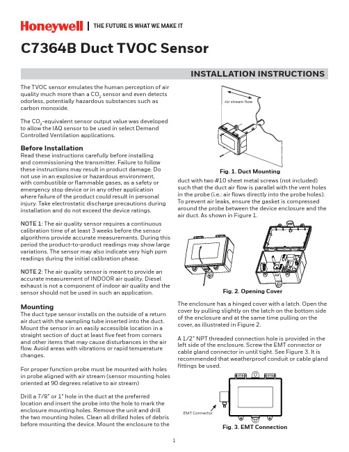
THE FUTURE IS WHAT WE MAKE ITC7364B Duct TVOC SensorINSTALLATION INSTRUCTIONSThe TVOC sensor emulates the human perception of air quality much more than a CO 2 sensor and even detects odorless, potentially hazardous substances such as carbon monoxide.The CO 2-equivalent sensor output value was developed to allow the IAQ sensor to be used in select Demand Controlled Ventilation applications.Before InstallationRead these instructions carefully before installing and commissioning the transmitter. Failure to follow these instructions may result in product damage. Do not use in an explosive or hazardous environment, with combustible or flammable gases, as a safety or emergency stop device or in any other application where failure of the product could result in personal injury. Take electrostatic discharge precautions during installation and do not exceed the device ratings.NOTE 1: The air quality sensor requires a continuous calibration time of at least 3 weeks before the sensor algorithms provide accurate measurements. During this period the product-to-product readings may show large variations. The sensor may also indicate very high ppm readings during the initial calibration phase.NOTE 2: The air quality sensor is meant to provide an accurate measurement of INDOOR air quality. Diesel exhaust is not a component of indoor air quality and the sensor should not be used in such an application.MountingThe duct type sensor installs on the outside of a return air duct with the sampling tube inserted into the duct. Mount the sensor in an easily accessible location in a straight section of duct at least five feet from corners and other items that may cause disturbances in the air flow. Avoid areas with vibrations or rapid temperature changes.For proper function probe must be mounted with holes in probe aligned with air stream (sensor mounting holes oriented at 90 degrees relative to air stream)Drill a 7/8” or 1” hole in the duct at the preferredlocation and insert the probe into the hole to mark the enclosure mounting holes. Remove the unit and drill the two mounting holes. Clean all drilled holes of debris before mounting the device. Mount the enclosure to theduct with two #10 sheet metal screws (not included)such that the duct air flow is parallel with the vent holes in the probe (i.e.: air flows directly into the probe holes). To prevent air leaks, ensure the gasket is compressed around the probe between the device enclosure and the air duct. As shown in Figure 1.The enclosure has a hinged cover with a latch. Open the cover by pulling slightly on the latch on the bottom side of the enclosure and at the same time pulling on the cover, as illustrated in Figure 2.A 1/2” NPT threaded connection hole is provided in the left side of the enclosure. Screw the EMT connector or cable gland connector in until tight. See Figure 3. It is recommended that weatherproof conduit or cable gland fittings be used.Fig. 3. EMT ConnectionThis device has a half-wave type power supply so the power supply common is the same as the output signal common. Therefore, several devices may be connected to one power supply and the output signals all share the same signal common. Use caution when grounding the secondary of an AC transformer or when wiring multiple devices to ensure that the circuit ground point is the same on all devices and the controller.Ensure the controller Analog Input (AI) matches the TVOC voltage output signal type before power is applied. The voltage signals have a minimum loadrating. Follow the ratings in the Specification section or inaccurate readings may result.Connect the LINEAR output signal to a 0-5 or 0-10 Vdc analog input port on the controller as shown in Figure 6. The device is factory configured for 0-5 Vdc output signal but may be changed to 0-10 Vdc via the menu. Changing output signal may be done during set up of the device. This linear output signal represents to 0-2000 ppm CO 2-equivalent value.The ASO (Analog Stepped Output) output signal is a second voltage signal that represents the three air quality levels of GOOD, FAIR, and POOR. Each level may be set independently via the menu to any value between 0 and 10 Vdc. The factory default is GOOD = 2.5 V, FAIR = 5.0 V, and POOR = 7.5 V. This signal canDUCT TVOC SENSORWiring•Deactivate the 24 Vac/dc power supply until all connections are made to the device to prevent electrical shock or equipment damage. Follow proper electrostatic discharge (ESD) handlingprocedures when installing the device or equipment damage may occur•Use 18-22 AWG shielded wiring for all connections and do not locate the device wires in the same conduit with wiring used to supply inductive loads such as motors. Make all connections in accordance with national and local codes.• Connector layout is shown in Figure 5. Diagram shown includes all options. If option is not ordered, connector will not be present.•Connect the positive DC voltage or the hot side of the AC voltage to the terminal marked POWER. The power supply common is connected to the terminal marked COMMON as shown in Figure 6.•The device is reverse voltage protected and will not operate if connected backwards.Fig. 4. Secure CoverFig. 5. PCB LayoutPOWER LINEARCOM PWR ASO LINEARN.O.RELAYUP DOWN MENUTwo security screws are provided which can be installed to help secure the cover once settings and wiringconnections are complete. See Figure 4.Fig. 6. WiringDUCT TVOC SENSORalso be connected to a controller analog input, or it can be connected directly to a 0-5 or 0-10 Vdc input of a damper actuator for direct ventilation control as shown in Figure 7. In this way, the Indoor Air Quality Sensor can be used as a stand-alone device. Since all steps are completely adjustable, the device can also drive a reverse acting actuator.The relay output available on the RELAY terminals. The relay output terminals are completely isolated from other connections and are NOT connected to the signal COMMON terminal as shown in Figure 8. This signal can be used to directly control an alarm, a ventilation fan or may be connected to a digital input of a Building Automation System for status monitoring. Respect the relay contact specification as listed in this document.Set-UpVerify that the TVOC sensor is properly wired and all connections are tight. Apply power to the device and note that the LCD will display the software versionnumber for a few seconds and then the device will enter Warm Up mode. The Warm Up mode will last for five minutes and the LCD will count down the time. This time is required to allow the device and sensor to reach normal operating temperature. After the five minutes has expired the device will enter normal operation and the LCD will indicate the TVOC status and ppm value.OperationIn normal operation, the TVOC sensor will detect a broad range of reducing gases such as CO and VOCs and translate the measurement into a parts per million (ppm) CO 2 equivalent value. This value is displayed on the LCD in either ppm or % as set in the menu. The air quality value is also displayed as either GOOD, FAIR or POOR and these values can also be set via the menu.The GOOD, FAIR and POOR air quality levels control the Analog Stepped Output (ASO) signal. The ASO output signal comprises of three independently set voltage levels that can be used to directly control a damper actuator for three positions. The levels are set via the menu and each level can be set anywhere from 0-10 Vdc. The GOOD, FAIR and POOR air quality levels will also be displayed on the tri-color front panel LED. The LED colors are displayed as GOOD = green, FAIR = blue and POOR = red. If required, the LED operation can be disabled via the menu.The air quality value is also sent to the LINEAR output as a 0-5 or 0-10 Vdc signal to represent the 0-2000 ppm CO 2 equivalent. This signal can interface to any voltage analog input for logging or control purposes.The linear output scaling and ASO operation is shown below. Note that the ASO GOOD/FAIR trip level = 1000 ppm and the FAIR/POOR trip level = 1500 ppm. The ASO output levels are GOOD = 2.5 V, FAIR = 5.0 V and POOR = 7.5 V.The normally open relay will close when the airquality exceeds a pre-set trip point. The trip point and hysteresis value can be programmed via the menu such that the relay closes when IAQ > Relay Setpoint and opens when IAQ < Relay Setpoint - Hysteresis. By default, the relay has a one minute minimum onand off time to prevent short cycling. This feature may be disabled via the menu. The menu may alsobe used to test the relay function. The relay can be used to control an alarm, fan directly or to signal a digital input.Fig. 7. ASO WiringFig. 8. Relay WiringASODUCT TVOC SENSOROther features and configuration are described in the Setup Menu section.NOTE: The air quality sensor requires a continuous burn-time of at least 3 weeks before the sensoralgorithms provide accurate measurements. During this period the product-to-product readings may show large variations. The sensor may also indicate very high PPM readings during the initial burn-in phase.The TVOC sensor is meant to provide an accurate measurements of INDOOR air quality. Diesel exhaust is not a component of indoor air quality and the sensor should not be used in such an application.MenuThe menu may be accessed any time after the initial warm-up period. The menu is controlled by using the three buttons on the PCB labeled UP, DOWN, and MENU. All values entered are saved in non-volatilememory and will be restored correctly in case of a power failure.The menu has several items as shown below. To enter the menu, press and release the <MENU> key while in normal operation. This will enter the User menu step 1, pressing the <MENU> key a second time advances to step 2. Each press of the <MENU> key advances the menu item. The <UP> and <DOWN> keys are used to make changes to program variables by scrollingthrough the available options. When a value is changed, use the <MENU> key to save it to memory and advance to the next menu item. Actual menu displays with the factory default value are shown.NOTE: If no keys are pressed for 2 minutes, the menu will automatically exit.IAQ Unit ppmThe LCD displays the IAQ sensor reading from 450-2000 ppm. Use<UP> or <DOWN> to change from ppm (default) to % for 0-100 % display. 0-100% = 450-2000 ppm. Thissetting has no effect on the LINEAR output signal, it is always scaled 0-2000 ppm = 0-5/0-10 Vdc.<MENU>Press to advance to next menu item1. IAQ UnitIAQ G/F 1000 ppmThis sets the trip point from Good to Fair IAQ for the LED and ASO. Thefactory default is 1000 ppm. Use <UP> or <DOWN> to change from 700 to 1200 ppm in 25 ppm steps.<MENU>Press to advance to next menu item2. IAQ G/F IAQ F/P 1500 ppmThis sets the trip point from Fair to Poor IAQ for the LED and ASO. The factory default is 1500 ppm. Use <UP> or <DOWN> to change from 1300 to 1700 ppm in 25 ppm steps. Note that both IAQ trip points have a 25 ppm hysteresis built in.<MENU>Press to advance to next menu item3. IAQ F/P Analog Out 5VThe LINEAR analog output signaldefaults to 0-5 Vdc. It can be changed with <UP> or <DOWN> to 0-10 Vdc. The selected scale is always equal to 0-2000 ppm.<MENU>Press to advance to next menu item4. Analog Output ASO Good 2.5 VdcThis sets the ASO output voltage for the Good range. It can be set using <UP> or <DOWN> anywhere from 0-10 Vdc. Resolution is 0.1 Vdc. The ASO output changes accordingly.<MENU>Press to advance to next menu item5. ASO Good Output ASO Fair 5 VdcThis sets the ASO output voltage for the Fair range. It can be set using <UP> or <DOWN> anywhere from 0-10 Vdc. Resolution is 0.1 Vdc and ASO out updates.<MENU>Press to advance to next menu item6. ASO Fair Output ASO Poor7.5 VdcThis sets the ASO output voltage for the Poor range. It can be set using <UP> or <DOWN> anywhere from 0-10 Vdc. Resolution is 0.1 Vdc and ASO out updates.<MENU>Press to advance to next menu item7. ASO Poor Output IAQ Cal 0 ppmUse <UP> or <DOWN> to add orsubtract an offset to the IAQ signal. This can change from -200 to + 200 ppm in 10 ppm increments.<MENU>Press to advance to next menu item8. IAQ CalibrationRelay Test OFFRelay SP 1000 PPMUse <UP> or <DOWN> to toggle the relay on or off for testing.Use <UP> or <DOWN> to change the relay setpoint from 750-1500 ppm. Default is 1000. Resolution is 25 ppm.<MENU>Press to advance to next menu item<MENU>Press to advance to next menu item9. Relay Test 10. Relay Set Point Relay Hy 100 PPMRelay Dly YESRelay Op NOCan change the relay hysteresis to 20, 50, 100, or 200 ppm. Default is 100.By default, the relay has a 1 minute minimum on time and a 1 minute minimum off time to prevent fast cycling. This feature can be disabled here.By default, the relay is normallyopen as its non-energized state. Use <UP> or <DOWN> to change to NC (normally closed).<MENU>Press to advance to next menu item<MENU>Press to advance to next menu item<MENU> Exits the User menu and returns the normal operation. The LCD flashes“Menu Exits” for 3 seconds.11. Relay Hysteresis 12. Relay Delay 13. Relay Open/ClosedDimensionsTHE FUTUREIS WHAT WE MAKE IT® U.S. Registered Trademark © 2020 Honeywell International Inc.Printed in Canada 31-00414-01WEEE Directive 2012/19/EC Waste Electrical and Electronic Equipment directiveAt the end of the product life dispose of the packaging and product in a corresponding recycling centre. Do not dispose of the unit with the usual domestic refuse. Do not burn the product.Honeywell Building TechnologiesIn the U.S.:Honeywell715 Peachtree Street NE Atlanta, GA WARNING: This product can expose you to chemicals which are known to the State of California to cause cancer/birth defects or other reproductive harm. For more information go to .。
- 1、下载文档前请自行甄别文档内容的完整性,平台不提供额外的编辑、内容补充、找答案等附加服务。
- 2、"仅部分预览"的文档,不可在线预览部分如存在完整性等问题,可反馈申请退款(可完整预览的文档不适用该条件!)。
- 3、如文档侵犯您的权益,请联系客服反馈,我们会尽快为您处理(人工客服工作时间:9:00-18:30)。
一、仪器简介及使用范围煤在我国已成为主要的一次能源,是国民经济的重要支柱。
特别是煤作为电厂的燃料,不但费用占电厂成本的70%以上,而且其特性对电厂的安全经济运行,设计、调整、监控锅炉燃料工况,降低发电成本等有着非常密切的关系。
因此分析煤的特性,能更好地发挥煤的作用,对电厂减亏增盈,提高经济效益有着十分重要的意义。
同时随着计算机技术的发展和普及,尤其是视窗(WINDOWS)操作系统的出现和完善,计算机已在煤质分析仪器中得到越来越广泛的应用。
MAC—2000全自动工业分析仪的开发研制,就是基于WINDOWS环境下开发和使用的,该仪器的出现,解决了原有工业分析方法中存在的劳动强度大、测试时间长等缺点。
仪器能采用多种分析方法、实时保存数据、调入历史数据、综合查询数据、实时打印数据等多项功能。
仪器的主要部件全部使用当今最先进的数字电路芯片,有很高的可靠性、稳定性、重现性。
是新一代高档次的煤质分析仪器。
仪器除用于煤炭行业外,在电力、科学研究、学院教学等领域也有广泛的用途。
二、工作原理仪器由计算机控制,通过数据采集卡对仪器主机进行自动控制与数据的实时采集。
仪器工作原理图MAC-2000型全自动工业分析系统可快速、自动、连续测定工业煤中的水分、挥发分、灰分和固定碳及利用工业分析结果自动计算高、低位发热量,并以不同基显示、打印分析结果。
每个煤样的分析时间约为20分钟。
在计算机的控制下,系统将自动称样、连续进样、显示、分析和打印结果,数据存储以备查询。
煤样在110℃、氮气氛中加热至恒重测定水分Mad;在900℃、氮气氛中加热七分钟测定挥发分Vad;在815℃、氧气氛中加热至恒重测定灰分Aad。
测定条件与国标方法(GB212-91)相同。
系统应用了国内成熟的发热量经验计算公式,对大多数中国煤种有较广泛的适用性。
本系统还兼有测定飞灰可燃物的功能,测定方法执行电力行业标准。
该仪器中采用的监督方法与仲裁方法均被设置,用户可根据需要选用。
每次飞灰可燃物的测定时间约5分钟。
本系统具有数据存储与数据处理功能,可根据用户需要方便地按时间、参数项进行选择查询并打印结果。
本系统还具有仪器校验功能,通过仪器调试可对仪器的硬件参数进行调整;通过数据校验可校准因环境与时间对硬件的影响而造成的系统误差。
三、主要技术指标1.煤样测定:适用范围:与国标GB212-91相同称样范围:0.3—0.5g测量数量:一次可完成十个样品的测试2.飞灰可燃物测定:重复性:Sx <0.2%准确性:Sx <0.4%3.测量时间:煤样:20分钟飞灰可燃物:5分钟左右4.仪器运行条件:氮气:纯度>99.99%;流量800ml/min氧气:普氧;流量800ml/min电源:220V AC,50HZ功率:<3KW环境温度:0-35℃技术指标:* 测温范围:室温~1500℃* 升温速度:≤900℃20℃~30℃/min>900℃5℃±1℃/min* 测温精度:±5℃* 试样数量:1~3个* DT≤40℃,ST、HT、FT≤30℃* 测试气氛:氧化性或弱还原性* 灰锥形态分辩率:纵向0.1mm横向0.3mm四、仪器的组成仪器主要由主机、计算机、精密电子天平、打印机与气源组成等部分组成:1、计算机:PⅢ800以上工控机、17′纯平。
2、打印机:彩色喷墨打印机。
3、仪器主机:仪器的控制与温度的采集、可控温加热炉、内置万分之一的精密电子天平。
4、应用软件一套。
五、安装和使用请小心拆开包装箱,先找到装箱单与使用说明书,再按装箱单上的品名与数量逐一清点箱内实物,找到一件就在装箱单上相应方各内打上记号,如发现物品与数量有误请及时与供货方联系。
➢实验室与实验台1、实验室电源应具有良好地接地。
2、实验室附近不应有振动源。
3、实验台面积不小于0.85×1.5平方米,台面高度以0.8平方米为宜。
➢气源1、氮气和氧气分别通过减压表、稳压器、连接器和导气管与主机对应接头,距离不大于2米。
2、各连接处应严密,不应有漏气。
➢调节调整主机三个底脚螺钉,使天平的水平气泡居中。
➢连接先将主机与计算机、计算机与打印机、电子天平与计算机的信号线连接好,再分别将电子天平、计算机和打印机的电源插头插好,最后将主机电源插头与电源接通。
➢打印机安装打印机安装详见打印机说明书。
➢天平调整本天平为万分之一精度天平,它的稳定性直接影响系统的分析精度,所以在通电的情况下应防止振动、撞击或移动。
使用时应避免强风对流。
➢操作手册1、本系统结构如下图所示:打开主机电源后,主机受计算机控制;前面板指示灯功能说明如下:HF----高温炉加热指示LF----低温炉加热指示↑↓--电机升降指示N2----通氮气指示O2----通氧气指示程序安装完成后在桌面上双击MAC-2000图标进入工作程序。
主菜单如下图所示。
主菜单分为“工业分析”,“系统设置,”“数据处理”,“帮助”四个部分2、软件部分说明主菜单及工具栏⑴工业分析(该菜单下有三个子菜单)①工业分析测试:点击该菜单,或点击工具栏上的“开始测试”进入工业分析称样窗体1、测试选项栏说明:内水分、灰分、挥发分、固定碳、飞灰可燃物、焦渣特征等六个选项,可进行适当的组合测试,可以单击复选框,选择需要进行的测试项(打勾项)。
2、样品输入栏说明:⑴样品名称、样品编号:用来标识样品;⑵焦渣指数、全水分:用来计算发热量;⑶内水分:当进行挥发分测定,而不进行灰分测时,必须输入;⑷碳酸盐:进行飞灰可燃物测定时,输入此项可使测定值更准。
3、按钮说明:⑴重新称重:对上一步的操作再做一次⑵读入上次数据:当上次实验没有完全完成时,按此键可调入未完成的样品的数据⑶称重:实验前对样品进行称重⑷结束:完成称样过程,开始实验⑸取消:中断称重,退出实验4、称样具体过程说明如下:①进入称样画面后,系统检测主机开关是否打开,如果没开则给出提示;②选择测试选项,默认时选择水分、挥发分、固定碳、灰分进行测试;③输入被测样品的样品编号等;④用鼠标按称样按钮,进样盘下降到称样位,称取坩埚皮重记为G0;⑤进样盘回复到高位后,取下坩埚,加入0.3—0.5g重的样品后,按称样按钮,称得质量记为G4,则样重Wt=G4-G0,如果Wt不在规定范围内则重复该步骤;⑥重复过程③→⑤进行下一个样品称重;⑦如果发现前面的输入项有错误,可在显示表格栏中双击该项,弹出样品编辑对话框如下图,进行修改后,点击OK 确认。
⑧当需要结束所有称样时按《结束》按钮,结束称样进入样品测试状态。
5、样品测试G0——坩埚重量;G1——灰分Aad 测定后坩埚+样品总重量;G2——挥发分Vad 测定后坩埚+样品总重量;G3——水分Mad 测定后坩埚+样品总重量;G4——坩埚+样品总重量。
测试过程具体如下:⑴ 等待炉温;T1=105(低温),T2=700(高温)⑵ 升降电机下降将样品送入低温炉内,通氮气N2 (800ml/min ),进行内水分测定,至样品恒重,记当前重量为G3,则内水分G4-G3Mad=G4-G0⑶ 等待炉温;T1=105(低温),T2=900(高温)⑷ 升降电机下降将样品送入高温炉内,通氮气N2 (800ml/min ),进行挥发分测定,等待7分钟,记当前重量为G2,则挥发分G3-G2Vad=G4-G0⑸ 等待炉温;T1=105(低温),T2=815(高温)⑹ 通氧气O2 (800ml/min ),进行灰分测定,至样品恒重,记当前重量为G1,则灰分G1-G0Aad=G4-G0⑺ 根据工业分析测定的数据及焦渣指数,通过经验公式计算出高位发热量Qgr,ad;⑻ 升降电机上升至高位,等待进行下一个样品的测试;⑼ 重复⑴→⑻进行下一个样品的测试。
② 工业分析调试选择工业分析菜单下的工业分析调试,运行调试程序如下:G4 G2 G1G0G3⑴设备状态区说明:11 1限转(1)样盘(0)1高位(1)中位(1)低位(1)炉子在正常高位样盘对准时炉位号为:限转为1、样盘为0、高位为1、中位为0、低位为0,炉位号为(11011100)2——二进制,即(EC)16——十六进制炉子在正常高位样盘未准时炉位号为:限转为1、样盘为0、高位为0、中位为1、低位为1,炉位号为(11000011)2——二进制,即(C3)16——十六进制炉子在中位样盘对准时炉位号为:限转为1、样盘为1、高位为1、中位为0、低位为1,炉位号为(11110101)2——二进制,即(F5)16——十六进制炉子在低位样盘对准时炉位号为:限转为1、样盘为1、高位为1、中位为1、低位为0,炉位号为(11110110)2——二进制,即(F6)16——十六进制(2)、天平读数:打开天平通讯后显示天平数据。
(3)、气体:为当前通气情况。
(4)、温度:实时显示当前室温、低温炉、高温炉温度。
⑵控制命令说明:⑴系统复位:计算机将所有输出口置为0。
⑵天平通讯:读取天平读数。
⑶进样盘转:炉子在正常高位时进样盘转动一格;⑷电机位置:升降电机运动到相应位置,如果进样盘位置不对则转一圈后再下降。
⑸称样位:升降电机下降到称样位置,可进行坩埚对中调试。
⑹氮氧气:可在通氧气、氮气、不通气间切换。
⑺加热:可使对应炉子加热到设定温度。
⑻退出:退出调试程序。
③、退出系统⑵系统设置在系统设置里,要求用户输入密码,初始密码为:1234561、密码修改选择系统设置里的密码修改,弹出密码修改对话框如下图:初始密码为:1234562、温度设置选择系统设置里的温度设置,弹出温度设置对话框如下图:用于高温炉和低温炉的温度设置,该项设置仅用于控制调试过程中的温度。
3、系统校准选择系统设置里的温度设置,弹出温度设置对话框如下图:校正系数K=标准值-测定值例如:Vad标准=26.35 Vad实测=26.10则:校正系数K=26.35-26.10=0.25故需要在校正系数的Vad项中输入0.25坩埚皮重项用于校正坩埚在常温下与高温状态下的差值。
G1 ——815°C下G2 ——900°C下G3 ——105°C下4、串行口设置可根据硬件配置情况来选择天平型号、波特率、通讯端口。
图中显示的及为默认设置。
5、化验室设置根据用户情况输入化验室名称,添加该化验室的化验员。
⑶数据处理1、数据查询选择数据处理中的数据查询,弹出数据查询对话框如下图:㈠查询条件包括:日期、样品编号、样品名称、Mad、Vad、Aad、Qgrad、飞灰,可以选择一项也可以选择多项进行查询。
㈡查询输入:当某项查询条件被选择后,该输入选项被激活,输相应的查询范围或名称后,点击查询按钮,系统将会将满足条的数据记录输出到表格中,并以不同基准来显示(Vd/VarAd/Aar项表示:如果Mt为零则表示干基,否则表示收到基)。