罗格斯
英国写实主义画家罗格斯戴尔画作

《1988年11月9日》(The Ninth of November, 1888)。
描述伦敦市长的游行。
《威尼斯圣马可广场》(Piazza of St Mark‘s Venice)。
这幅作品被英国皇家艺术学院评为“年度绘画作品”。
圣马可广场是威尼斯的中心广场,无数艺术家描绘过这个广场,罗格斯戴尔的这幅作品最为写实。
罗格斯戴尔(William Logsdail,1859-1944)是一位多产的英国画家,美国《时代》评价他的绘画技巧“完美无瑕”。
他的风格是写实主义,很多作品被英国皇家购买,至今无法看到。
罗格斯戴尔的作品在英国皇家艺术学院,英国皇家艺术协会,Grosvenor Gallery画廊,New Gallery 画廊和其他画廊展出。
罗格斯戴尔出生在英国的工业重镇,林肯群(Lincolnshire)的林肯市(Lincoln),这里设计生产过世界上第一辆坦克。
右图是林肯市的林肯博物馆里的Mark IV 型坦克。
当时为了保密,这辆坦克被称为美索不达米亚运水车(Water carrier for Mesopotamia),后来简称为水箱(water tank),最后变成一个单词坦克(tank)。
罗格斯戴尔的父亲是教堂管理人,他小时候曾当过教堂导游。
他先后在英国和比利时学习绘画,多次获奖。
1880年,21岁的罗格斯戴尔上学期间的一幅作品《渔人市场》(The Fish Market)被维多利亚女王买进Osborne House王宫。
1880年秋天,他开始访问威尼斯,并游历了埃及和中东等地,创作了很多当地风情的绘画作品。
1912年,他当选英国皇家肖像画家协会(Royal Society of Portrait Painters)的成员。
1944年,他以85岁的高龄去世。
他的很多作品留存在皇家或者贵族的私人收藏。
《老威尼斯的一个角落》(A Corner of Old Venice)。
《维罗纳的一个院子》(A Courtyard in Verona)。
罗格斯公司2929纯粹纸型多层板处理指南说明书

2929 BondplyMulti-Layer Board Processing GuidelinesMATERIAL DESCRIPTION: 2929 bondply is an unreinforced, hydrocarbon based thin film adhesive system intended for use in high performance, high reliability multi-layer constructions.A low dielectric constant (2.9) and loss tangent (<0.003) at microwave frequencies makes it ideal for bonding multi-layer boards (MLB’s) made using PTFE composite materials such as RT/duroid® 6000 and RO3000® series laminates, filled hydro-carbon r esin c omposites s uch a s R O4000® c ores, a nd s pecialty t hin core laminates. The proprietary cross-linking resin system makes this thin film adhesive system compatible with sequential bond processing while controlled flow characteristics offer excellent blind via fill capability and potentially predictable cutback ratios for designs requiring blind and/or buried cavities. 2929 bondply is compatible with traditional flat press and autoclave bonding. The film is currently available in 0.0015”, 0.002”, and 0.003” thick sheets. Individual sheets can be stacked to yield thicker adhesive layers. The unreinforced thin film can be tack bonded to inner-layers to ease simultaneous machining of cut-outs through core and adhesive layers and to facilitate formation of vias using conductive pastes. An easy to release carrier film protects the adhesive layer from contamination during machining, screening of conductive pastes, and MLB booking. These processing guidelines offer current “best practice” procedures and parameters for bonding MLB’s using 2929 bondply. The recommendations will be updated as additional information becomes available. A Rogers’ Technical Service Engineer (TSE) should be consulted for our latest information. All first-time users are urged to contact a Rogers’ TSE, Sales Engineer (SE), or Applications Development Manager (ADM) for evaluation/ demonstration s amples a nd s pecial h andling i nstructions. A v ideo showing the recommended technique for laying up a multilayer using 2929 Bondply can be viewed in the video section on the Rogers Technology Support Hub: /techub. STORAGE: Materials should be stored between 10 to 30°C (50 to 80°F) and relative humidity less than 60%. The uncured material should be shielded from long-term exposures to UV light. 2929 bondply s hould b e u sed w ithin s ix m onths o f t he d ate o f s hipment.DESIGN CONSIDERATIONS: The post-bond thickness of 2929 bondply can be predicted using the following formula. It should be noted that copper distribution, planarity of platens and caul plates, layer count, compressible padding, etc… will effect the final thickness and uniformity thereof. The following calculation can be used as a starting point to predict post-bond core:core spacing, but fine tuning based upon actual thickness measurements is recommended.Core: core spacing = 2929 + (Side A Cu thk X retained Cu) + (Side B Cu thk X retained Cu) where:Core: core spacing is distance between etched core surfaceson opposing (A & B) sides of 2929 bondply. The distance is measured from the base of copper features.2929 is pre-press thickness of 2929 adhesive.Side A and Side B Cu thickness is the thickness of the copper layers on the A and B side of the 2929 bondply. Typically, 0.5ED would be 0.0007” while 1ED would be 0.0014”.Retained Cu is the percent of copper remaining on surfaceA andB after inner-layer preparation divided by 100. A solid copper plane would be 100%/100 = 1.0.Example:2929 thickness = 0.004”Side A Cu thick = 0.0007” (0.5E)Side B Cu thick = 0.0014” (1E)Side A retained Cu = 0.25 (25%/100)Side B retained Cu = 0.5 (50%/100)Core: core spacing =0.004” + (0.0007 X 0.25) + (0.0014 X 0.5) = 0.0049”Note: Cu:Cu spacing would be0.0049” – (0.0007” + 0.0014”) = 0.0028”FORMATION OF TOOLING HOLES: Tooling holes can be punched or drilled as single sheets or in stacks of multiple sheets. The maximum recommended stack height for punching holes is ten sheets. The maximum recommended stack height for drilling holes is 25 sheets providing a new drill and proper parameters are used.For either hole formation technique, the 2929 sheets should be stacked between layers of pressed phenolic entry material with the PET side on top. A release sheet should be placed between the phenolic sheet and the bottom layer of 2929 to avoid welding the adhesive to the exit material during formation of the tooling holes. The white tag stock paper used to package 2929 for shipment can be used as the release layer.Tooling holes can be punched as standard. Holes should be drilled using 200 SFM and a 0.0015”/” infeed rate. The default parameters for all drill diameters greater than 0.060” are 20 KRPM spindle speed and 25 IPM infeed. INNER LAYER PREPARATION: Innerlayer metal surfaces should be oxide treated to promote mechanical adhesion. A wide range of oxide alternatives and some reduced black or brown oxides have been used successfully with 2929 Bondply. The thermal capabilites of a given oxide treatment must be understood in order to select the appropriate lamination temperature.Please refer to the specific laminate manufacturers’ data sheets and processing guidelines for any recommended treatment of the etched dielectric surfaces and also to insure the laminates can tolerate the lamination temperature required for 2929 Bondply. MULTILAY ER LAY UP (Reference 2929 instructional video noted on page 1): The uncured adhesive layer is fragile. The release sheet facilitates handling, serves as a protective barrier against contamination, and should not be removed until after the adhesive layer has been punched, machined (cavity designs), and positioned onto the inner-layer surface. Once positioned onto the inner-layer surface, the carrier film should be carefully peeled beginning in one corner and peeling toward the diagonal corner. The preferred method of initiating the separation process involves bending one corner of the adhesive over until the PET carrier is in contact with itself. Pressing on the bend will snap the adhesive layer. The PET carrier can be slid toward the opposing corner while maintaining a slight downward pressure. The free hand should be used to hold down the adhesive layer during removal of the release liner. Special care may be required to avoid tearing of the adhesive layer near tooling holes and cut-outs. Pre-releasing and replacing the PET layer may prove helpful before machining cut-outs or when booking very thin (0.0015”) adhesive layers.Handling, especially of thin (<0.002” thick) layers, can be facilitated through the use of tack bonding. Tack bond is possible using a hot roll laminator at 125°C (275°F), 6” per minute feed rate, and 30 PSI. Tack bonding is also possible at 110°C (230°F) providing the feed rate is slowed to 2” per minute feed rate.Tack bonding can be accomplished using a vacuum lamination system. Parameters would include a 60-90 second dwell with bondline temperatures between 115 to 140°C (240 to 285°F). When possible, tooling holes should be formed after the tack bonding process. When properly applied, the tack bond should remain intact for 2-4 days and the adhesive layer should remain fully functional. Note: As is true with many bonding materials,the use of compressible padding placed internal to the tooling plates is recommended to improve pressure uniformity across the multilayer book. When selecting a press pad material, it is important to insure the material is properly rate for the selected bonding temperature. In addition, some designs may rquire additional conformance. In those cases, the use of skived PTFE or similar products have been used successfully between the multilayer panel and the stainless steel separators plates.MLB BONDING CYCLE: The press cycle should include a 2.5°C - 4.0°C/min (4.5°F - 7.0°F/min) ramp rate from room temperature to 245-250°C (473 to 482°F) and a 90-120 minute dwell at 245-250°C.NOTE: 2929 bondply can be bonded at lower temperatures if required t o c ompensate f or l ess t hermally r obust o xide t reatements.However, the absolute minimum product temperature must be above 224°C (435°F). Dwell time should be 120 minutes when cure temperature is less than 245-250°C (473 to 482°F). The recommended applied pressure for the entire cycle is 400 PSI, although pressure can be increased or decreased through evaluation to control flow of the resin/filler system. Vacuum assistance is preferred, but not required. Cooling can be accomplished in the hot press or after a transfer to a cold press for an accelerated rate of cooling. 2929 bondply is also compatible with a utoclave b onding u sing t he t hermal p rofile d escribed a bove.The information in this process guide is intended to assist you in designing and fabricating PWB’s with Rogers’ circuit materials. It is not intended to and does not create any warranties express or implied, including any warranty of merchantability or fitness for a particular purpose or that the results shown on this data sheet will be achieved by a user for a particular purpose. The user should determine the suitability of Rogers’ circuit materials for each application.Prolonged exposure in an oxidative environment may cause changes to the dielectric properties of hydrocarbon based materials. The rate of change increases at higher temperatures and is highly dependent on the circuit design. Although Rogers’ high frequency materials have been used successfully in innumerable applications and reports of oxidation resulting in performance problems are extremely rare, Rogers recommends that the customer evaluate each material and design combination to determine fitness for use over the entire life of the end product.These commodities, technology and software are exported from the United States in accordance with the Export Administration regulations. Diversion contrary to U.S. law prohibited.RT/duroid, RO4000, RO3000 and the Rogers’ logo are trademarks of Rogers Corporation or one of its subsidiaries.© 2021 Rogers Corporation, Printed in U.S.A, All rights reserved.POST-MLB BOND PROCESSING: With minor exceptions,bonded MLB’s should be processed using procedures and parameters associated with the core layers. Thin sub-assemblies should be handled carefully after bonding to avoid excessive bending. 2929 can be desmeared chemically or using plasma. A plasma cycle is provided below. The adhesive system does not require special sodium or plasma wettability treatments prior to plating, but 2929 is compatible with these processes should they be required for the core layers.Plasma Desmear CycleFrequency: 40 KHz Voltage: 500-600VPower: 4000-5000Watts Pre-Heat to 60°C using:Gases: 90% O2, 10% N2Pressure: 250mTORRDesmear using:Gases: 75% O2, 15% CF4, 10% N2Pressure 250 mTORR Time 10-15 minutes。
罗格斯大学博士录取难度详细介绍

罗格斯大学博士录取难度详细介绍罗格斯大学博士录取难度详细介绍罗格斯大学认可度罗格斯大学国内认可度较高,学校是美国最早成立的第八个高等教育机构,也是美国独立____前的九所私立殖民地学院之一。
同时学历也是受到中国教育部认可的,该大学是在中国教育部认可之列的,所以这所大学所颁发的学士学位和硕士学位等证书都是受到中国教育部的认可的。
罗格斯大学申请难度罗格斯大学申请难度不大,学校本科申请要求高中毕业,高中GPA平均分要求3.5以上,雅思成绩要求6.0分以上,单项最低要求6.0,托福分数最低要79分以上,其中阅读、听力、写作要求22,口语需达24,学校的申请要求与耶鲁大学,哥伦比亚大学,斯坦福大学要求托福100分以上相比,罗格斯大学申请难度不大。
罗格斯大学申请日期:留学申请截止日:12月1日提早行动申请截止日:11月1日罗格斯大学费用详情年均学费:$29160年均生活费:$14530其他费用:$2781罗格斯大学博士申请流程第一步:参加TOEFL,GRE或GMAT考试第二步:将申请材料提交给大学,GRE和TOEFL分数只有通过考试中心ETS寄出,才被认为是正式有效的第三步:联络大学教授,进展套磁第四步:大多数的PhD工程Deadline都是12月1日,即便套词环节非常不理想,到了这个时间也需要提交申请申请材料的。
第五步:收到材料以后,学校会安排面试。
教授直接面试,或者Admission Committee 安排1-2教授Perform Interview,主要是进一步理解研究方向,career plan 以及口语程度等。
罗格斯大学学术合作罗格斯大学纽瓦克校区商学院及公共事业管理学院与东北师范大学达成协议,在东北师范大学净月校区成立了东北师范大学罗格斯大学纽瓦克学院,开设金融学,物流管理〔供给链管理〕,公共事业管理三个专业。
该工程为全国各地的应届高中毕业生提供专业课全英语授课,目前提供4+0、3+1、2+2等形式,毕业后同时授予东北师范大学和罗格斯大学双学士学位。
罗格斯 RO3000 系列玻璃纤维复合材料数据表和加工指南说明书

Data Sheet and Processing Guidelines for RO3000® Series BondplyRogers RO3000® series bondply is an undensifi ed version of RO3000 laminates that can be used to process highlyreliable, homogeneous RO3000 multi-layer boards (MLB’s). The bondply is used in a manner analogous to prepreg in FR-4 constructions and, once bonded, becomes the equivalent of a normal RO3000 core layer.RO3000 series bondply offers electrical and thermal-mechanical advantages over most other adhesive systems that can be used to bond RO3000 material multi-layer constructions. In addition, improvements offered by bondply layers over core-to-core fusion bonding include improved layer-to-layer registration, tighter control over Z-axis spacing of copper layers, better encapsulation of buried metal features at lower applied pressures, and design fl exibility.During a MLB bonding process, the bondply will reduce in thickness to about fi ve mils and closely match predictable electrical properties. A Rogers’ Technical Support Engineer (TSE) should be contacted for design data.PROCESSING GUIDELINES:INNER-LAYER PREPARATION:Cores should be processed through inner-layer as standard. If copper roughening is required (ground or power planes), a microetch or a subtractive process oxide alternative such as Atotech’s Bondfi lm or MacDermid’s MultiBond LE should be used. Traditional additive process oxide treatments lack the thermal stability to survive the high temperature bond conditions.PTFE activation by sodium or plasma treatment should be avoided. All inner-layers should be baked at 125°C to 150°C (257°F - 302°F) for at least one hour prior to MLB bonding.PREPARATION OF MLB BOOK:RO3000 bondply layers require careful handling to avoid tearing. Pinning holes can be punched, drilled, or routed. Entry material should be used during drill or rout to shield the bondply layers from debris.Due to in-plane expansion characteristics, type 304 stainless steel separator plates are recommended. Five to ten mil thick sheets of aluminum should be placed between the multi-layers and the separator plates.Foil bonding of outer-layers is possible but a Rogers’ Technical Service Engineer should be consulted prior to processing foil-bonded constructions.BOND CYCLE:Temperature control is most critical between 600°F (315°C) and 700°F (371°C) during the ramp up, and between 700°F (371°C) 500°F (260°C) during the cool down. The ramp rate to 600°F (315°C) can be up to 10°F (5.5°C)/min, but the ramp from 600°F (315°C) to 700°F (371°C) should be 5°F (2.7°C)/Min. The dwell at 700°F (371°C) should be 30-60 minutes. The cooling rate to 500°F (260°C) should be at a rate of 2°F (1.1°C)/Min. An accelerated cool can be used, but materials should remain in the press until package temperatures are less than 250°F (121°C).Applied pressure will depend upon press (autoclave or fl at bed) equipment and fi ll requirements, but will probably fall into a range of 250 to 500 PSI.OUTER-LAYER PROCESSING:Standard processing guidelines for RO3000 cores would serve as the best starting point for processing homogeneous multi-layer constructions.Chart 2: RO3000 Bondply Speci fi c Gravity vs. Bond PressureThe data in Chart 1 demonstrates the excellent stability of speci fi c gravity over bond pressure of RO3003, RO3006, andRO3010 bondply.Chart 1: RO3000 Bondply Thickness vs. Bond PressureThe data in Chart 1 demonstrates the uniform thickness over bond pressure of RO3003™, RO3006™, and RO3010™ bondply.Dielectric Constant, εrProcess 3.00 ± 0.04(2) 6.15 ± 0.1510.2 ± 0.30Z-10GHz 23°CIPC-TM-6502.5.5.5Clample Stripline(2) Dielectric Constant, εr Design 3.00 6.5011.20Z-8 GHz - 40 GHzDifferentialPhase LengthMethodDissipation Factor0.00100.00200.0022Z-10GHz 23°C IPC-TM-650 2.5.5.5ThermalCoeffi cient of εr-3-262-395Z ppm/°C10GHz50 to 150°C IPC-TM-650 2.5.5.5Dimensional Stability-0.060.07-0.27-0.15-0.35-0.31XYmm/m COND AIPC TM-6502.2.4VolumeResistivity107105105MΩ•cm COND A IPC 2.5.17.1 SurfaceResistivity107105105MΩCOND A IPC 2.5.17.1 TensileModulus90020681500X,Y MPa23°C ASTM D638Moisture Absorption 0.040.020.05-%D48/50IPC-TM-6502.6.2.1Specifi c Heat0.90.860.8J/g/K Calculated ThermalConductivity0.500.790.95-W/m/K80°C ASTM C518Coeffi cient of Thermal Expansion 171625171724131116XYZppm/°C-55 to 288°CASTMD3386-94Td500500500°C TGA ASTM D3850 Density 2.1 2.6 2.8gm/cm3Flammability94V-094V-094V-0ULLead-Free ProcessCompatible Yes Yes YesCorporation.Shelf Life: Two years from date of shipment(1) References: Internal T.R.’s 1430, 2224, 2854. Tests at 23°C unless otherwise noted. Typical values should not be used for specifi cationlimits.(2) The nominal dielectric constant of an 0.060” thick RO3003 laminate as measured by the IPC-TM-650, 2.5.5.5 will be 3.02, due to theelimination of biasing caused by air gaps in the test fi xture. For further information refer to Rogers T.R. 5242.0.005” (0.13mm)RO3003: 25.5”X18”RO3006: 25.5”X18”RO3010: 25.5”X18”The information in this data sheet is intended to assist you in designing with Rogers’ circuit materials. It is not intended to and does not create any warranties express or implied, including any warranty of merchantability or fi tness for a particular purpose or that the results shown on this data sheet will be achieved by a user for a particular purpose. The user should determine the suitability of Rog-ers’ circuit materials for each application.These commodities, technology and software are exported from the United States in accordance with the Export Administration regulations. Diversion contrary to U.S. law prohibited.The Rogers’ logo, Helping power, protect, connect our world, RO3000, RO3003, RO3006, and R03010 are trademarks of Rogers Corporation or one of its subsidiaries. ©2016 Rogers Corporation, Printed in U.S.A., All rights reserved.Revised 1258 121216 Publication #92-147。
罗格斯大学简介
罗格斯大学 RutgersUniversity 是一所在美国享有盛誉的公立大 学。其中新布朗斯维克分校(又译作新伯朗士威分校)以科学研究见 长,拥有数量众多的世界一流学者在此任教,是美国科研实力最强的 大学之一,现有 49 位美国科学与艺术学院(AAAS)院士、18 位美国 科学院及工程院院士在此任教,并有 5 位校友及教授曾获得诺贝尔 奖,四位教授获得过普利策奖,一位教授曾获得过被称为”数学界诺 贝尔奖“的菲尔兹奖,一位教授获得过权威数学奖沃尔夫奖,
罗格斯大学新布朗维克主校区(Rutgers University New Brunswick)是一所世界一流的研究型大学,其在数学、统计学、信息 科学、计算机科学、情报学以及部分人文科学领域拥有一批世界著名 的学者与研究员,因而具有雄厚的研究实力。根据世界大学学术排名 ARWU2010 世界一流大学学术排名,罗格斯大学新布朗维克校区被 列入世界第 54 名。罗格斯大学新布朗维克分校校风良好且设备优良 。
/皮斯卡特维,纽华克以及肯顿。学校里的学生数量有 38,576 名本科 生, 12,904 名研究生,教师数量教职员 2,552 人 ,校园面积超大。罗 格斯大学的主要校园位于新布朗斯维克和皮斯卡特维,另有两个分 校在纽瓦克和肯顿。罗格斯大学由 29 个大学学院构成,其中 16 个学 院并另提供大学以上之研究所或专业学位。罗格斯大学提供超过 100 个学士学位、100 个硕士学位以及 80 个博士或专业学位。罗格斯大 学是新泽西州在美国大学协会(Association of American University) 唯一一所公立大学。另外一所加入该组织的本州大学是普林斯顿大 学(Princeton University)。该协会的其他会员都来自于北美以研究为 主导的著名大学。
罗格斯新泽西州立大学新布朗斯维克校区
传媒、图书馆与信息技术
工程学院
生物资源工程、化学工程、土木工程、电子与计算机工程、工业系统工程、材料科学与工程、机械与航天工程、生物医药工程
管理与劳工学院
劳动力与雇佣关系、人力资源管理
教育学院
教育心理学、教育理论、早期儿童教育
社会工作学院
社会学
护理学院
护理
费用
课程类别
费用(年)(美元)
总计(美元)
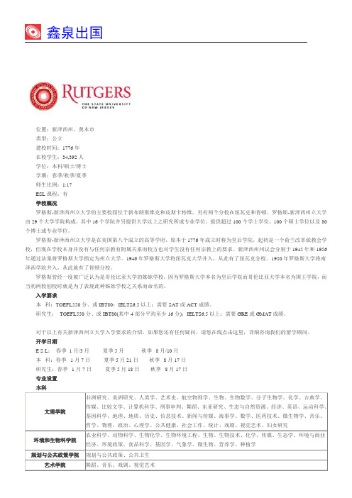
位置:新泽西州,奥本市
类型:公立
建校时间:1776年
在校学生:34,392人
学位:本科/硕士/博士
学期:春季/秋季/夏季
师生比例:1:17
ESL课程:有
学校概况
罗格斯-新泽西州立大学的主要校园位于新布朗斯维克和皮斯卡特维,另有两个分校在纽瓦克和肯顿。罗格斯-新泽西州立大学由29个大学学院构成,其中16个学院并另提供大学以上之研究所或专业学位。提供超过100个学士学位、100个硕士学位以及80个博士或专业学位。
对于以上有关新泽西州立大学入学要求的介绍,如果您还有任何疑问,请您在线点击这里,详细咨询我们的留学顾问。
开学日期
E S L:春季1月/3月夏季5月秋季8月/10月
本科:春季1月7日夏季5月21日秋季8月17日
研究生:春季1月7日夏季5月18日秋季8月17日
专业设置
本科
文理学院
非洲研究、美洲研究、人类学、艺术史、航空物理学、生物、生物数学、分子生物学、化学、古典学、传媒、比较文学、计算机科学、刑事审判、舞蹈、东亚研究、生态与自然资源、经济、英语、运动科学、基因科学、地理、地质、历史、信息技术、新闻与传媒、海事学、数学、医药技术、微生物学、音乐、哲学、物理、政治、心理学、公共健康、社会工作、统计、戏剧、视觉艺术、妇女研究
罗格斯大学

校园面积
罗格斯大学(Rutgers University)位于新布朗斯维克的主校区校园面积极大,总体占地2,688英亩 (10.88平方公里),分为五个分校区(College Avenue,Busch Campus,Livingston Campus,Douglass Campus,Cook Campus),横跨拉里坦河,整个校园成半环状将新布朗斯维克市环绕。
哈佛大学(常春藤盟校),威廉与玛丽学院,耶鲁大学(常春藤盟校),普林斯顿大学(常春藤盟校),哥 伦比亚大学(常春藤盟校),布朗大学(常春藤盟校),宾夕法尼亚大学(常春藤盟校),达特茅斯学院(常春 藤盟校)。罗格斯大学曾经一度被广泛认为是纽约的哥伦比亚大学的姊妹学校,因为罗格斯大学本名为皇后学院, 而哥伦比亚大学本名为国王学院(King's College),而当初两校创校时就是为了表现此种姊妹学校之关系而命 名的。
5.大学在地理位置上位于纽约和费城中间,学生们可以很方便地访问这两个美国最著名的城市。
罗格斯大学在人文学科上的长期处于领先地位,据2012年位列 Times Higher Education (U.K.)全美人 文学科第9位。 同时,罗格斯大学于哲学领域卓越异常,根据2014年权威性的The Philosophical Gourmet Report中对全美及全英语系国家大学哲学系的评鉴,罗格斯大学的哲学系在全美排名第2(仅次于纽约大学), 在全英语系国家排名第3(仅次于纽约大学及牛津大学),尤其形而上学、知识论及语言哲学等研究领域排名第 1。
纽瓦克校区(Newark Campus),位于纽瓦克市中心,占地约三到四个街区,以商学院和医学院为主,MBA总 部及公共事务与管理学院亦位于此校区;纽瓦克市为新泽西州第三大城市,亦是主要国际机场纽瓦克国际机场 (Newark International Airport)所在地,与纽约仅20公里距离,约半小时车程。
罗格斯公司高频材料的铜片说明说明书

Copper Foils for High Frequency MaterialsCopper foils, for the wide range of Rogers’ high frequency circuit substrates, are designed to provide optimum performance in high reliability applications.There are various types of copper foil are offered; in a range of weights (thicknesses). Their characteristics differ, and an understanding of these differences is important to ensure the correct selection of copper foil for each application or environmental condition.Copper Foil ManufacturingStandard ED CopperIn an electrodeposited copper manufacturing process, the copper foil is deposited on a titanium rotating drum from a copper solution where it is connected to a DC voltage source. The cathode is attached to the drum and the anode is submerged in the copper electrolyte solution. When an electric field is applied, copper is deposited on the drum as it rotates at a very slow pace. The copper surface on the drum side is smooth while the opposite side is rough. The slower the drum speed, the thicker the copper gets and vice versa. The copper is attracted and accumulated on the cathode surface of the titanium drum. The matte and drum side of the copper foil go through different treatment cycles so that the copper could be suitable for PCB fabrication. The treatments enhance adhesion between the copper and dielectric interlayer during copper clad lamination process. Another advantage of the treatments is to act asanti-tarnish agents by slowing down oxidation of copper.Fig. Electrodeposited Copper Manufacturing ProcessPropertiesRolled CopperRolled copper is made by successive cold rolling operations to reduce thickness and extend length starting with a billet of pure copper. The surface smoothness depends on the rolling mill condition.Fig. Rolled Copper Manufacturing ProcessResistive CopperThe matte side of the ED copper is coated with metal or alloy that acts as a resistive layer. The next process is to roughen the resistive layer with nickel particles.Reverse Treated ED Copper and LoPro Copper FoilReverse treated foils involve the treatment of the smooth side of electrodeposited copper. Treatment layers are thin coatings that improve adhesion of the base foil to dielectrics and add corrosion resistance which makes the shiny side rougher than it was before. During the process of making circuit board panels, the treated side of copper is laminated to the dielectric material. The fact that the treated drum side is rougher than the other side constitutes a greater adhesion to the dielectric. That is the majoradvantage over the standard ED copper. The matte side doesn’t need any mechanical or chemical treatment before applyingphotoresist. It is already rough enough for good laminate resist adhesion.In case of the LoPro™ copper, a thin layer of adhesive is applied on the reverse treated side of the copper. There is a physical layer of the bond enhancement material. Just like the reverse treated electrodeposited copper, the adhesive treated side is bonded to the dielectric layer for better adhesion. Our RO4000 series material are available laminated with LoPro copper foil. Crystalline StructureElectrodeposited copper crystals tend to grow lengthwise in the Z-axis of the foil. Typically, a polished cross-section ofelectrodeposited copper foil has the appearance of a picket fence, with long crystal boundaries perpendicular to the foil plane. Rolled copper crystals are broken and crushed during the cold rolling operation. They are smaller than the electrodeposited crystals, and have irregular, spherical shapes, nearly parallel to the foil plane.Copper Foil Roughness MeasurementsSurface roughness can be measured by mechanical and optical methods. Many sources report the “Rz” (peak to valley”) profile as measured by a mechanical profilometer . However, in our experience, the Sq (RMS) profile as measured by white light interferometry of the treated side of copper foil correlates best with conductor losses. Figure 1 shows the interferometer profile of the ½ oz. ED foil used on Rogers’ PTFE and TMM laminates. Table 1 shows the types of copper foils used on Rogers’ laminate materials along with typical profile information. A recent study (reference 7) has shown that the “top side” profile has a very different structure than the treated side and has very little effect on conductor loss, even in a stripline configuration.Treated SideShiny SideFig 1. Surface topographies of ½ oz electrodeposited foil by white light interferometryAs displayed on Table 1, roughness data of electrodeposited and rolled copper foils with different thicknesses was obtained by using an optical surface profiler. It also shows for which products the individual copper foils are used at Rogers Corporation. The rolled copper with no surface treatment is typically the smoothest.Table 1: Typical Root Mean Square Roughness ValuesElectric Performance of LaminatesIt has been well-known since the earliest days of microwave engineering with wave guides that the conductor surface roughness can substantially affect the conductor loss. In 1949, S.P. Morgan (1) published results of numerical simulations that indicated that a factor of two increase in conductor loss could be caused by surface roughness. Hammerstad and Jensen (2), incorporated Morgan’s model, along with correlated data in microstrip design method. The H&J model became the “textbook” (3) method for calculating the effect of surface roughness on conductor loss. More recently, at higher frequencies and with thinner laminates,it was found that H&J significantly under predicted the increase in conductor loss with surface roughness (5,6). The “Hall-Huray” model (4), developed from a “first principles” analysis, has been recently incorporated into commercial design software.In our experience, with modest adjustments to the input parameters, the Hall Huray model can accurately predict conductor loss over a wide range of laminate thicknesses and frequencies. The Hall-Huray model has been incorporated in Rogers Corporation’s impedance and loss calculator, MWI. We are currently working to develop the best Hall-Huray input parameters for modeling Rogers’ laminates. Please check at Rogers Technical Support Hub on-line or your Rogers Sales Engineer for updates.Rogers copper foils studies (5,6,7) have also shown that the copper profile can affect the propagation constant, with higher profile foils leading to an apparent increase in the effective dielectric constant Figure 3 shows the calculated dielectric constant of 50 ohm TLs on 4 mil liquid crystal polymer (LCP) laminates clad with different foils with Sq values ranging from 0.4 to 2.8 microns. The circuit with the highest profile foil exhibits an increase in DK of nearly 10%. The effect of copper profile on phase response is not accounted for in the Hall Huray model.The effect of copper profile on insertion loss can be quite large (Fig.2). At 90 GHz, the insertion loss of a 50 ohm TL fabricated from a 0.004” thick liquid crystal polymer (LCP) laminates with RA foil (blue line), is 2.2 dB/inch and is nearly perfectly modeled as a smooth conductor. The same substrate clad with ED foil exhibiting with Sq value of 2.0 microns, exhibits an insertion loss of 3.7 dB/inch. Figure 4 shows the morphologies of the roughness treatments on the conductors used to generate the data presented in Figure 2.Fig 2. Comparisons of different copper roughness on the insertion loss of microstrip transmission linesFig 3. Comparisons of different copper roughness on the dielectric constant of microstrip transmission lines0.4 m m RMS 2.0 m m RMS2.8 m m RMSFig. 4: SEM images of 1/2 oz copper foils - Treated SideMechanical Performance of LaminatesA. Thermal Shock ResistanceUnder some extreme conditions of rapid thermal cycling, electrodeposited copper may exhibit thermal stress cracks in narrow conductors. Under similar conditions, rolled copper has significantly improved resistance to cracking. Although electrodeposited copper has greater tensile strength and elongation before breaking, rolled copper has better elastic elongation before reaching permanent deformation.B. Foil AdhesionBecause the adhesion of resin systems to metals is predominantly mechanical, bond strength is directly related to the surface roughness of the treated foil side. Typical peel strengths after thermal shock for 1 oz. copper foils toC. Bondability of Stripline Assemblies (PTFE Substrates)The SEM photographs below illustrate the differences in topography and roughness between copper types and etch dielectric surfaces. If the boards are to be adhesive bonded, then for electrodeposited copper, sodium etch or plasma etch of the dielectric surface is not necessary, provided that care is exercised to preserve the surface topography. However, for rolled copper-clad circuit boards, the surface roughness of the dielectric will give a poor mechanical bond, and surface treatment is necessary for reliable chemically bonded assemblies.PropertiesThe different manufacturing methods of the two types of foil lead to differences in the electrical andMechanical properties. The primary differences are listed in Table 2.* Values represent properties after lamination to a PTFE laminate.Rogers Statement on Resistive Foil Visual Appearance and Resistivity ExpectationsRogers Advanced Connectivity Solutions (ACS) produces upon request a select number of copper clad laminates using commercially available, subtractively processed resistive foils. Resistive foil technology enables the use of planar resistors within the circuit boards that are made from our laminate products. The availability of these resistive foils varies dependingon each particular copper clad laminate product offered by ACS. However, in general ACS uses both OhmegaPly® foil from Ohmega Technologies, Inc. (/) and TCR® foil from Ticer Technologies (/). ACS customers are encouraged to research the specific resistive foil products that are available as well as the performance and processing details from each foil supplier prior to placing orders with Rogers.(1) Typical values are mean values derived from populations of measurements involving multiple lots of the specific foil type.The information in this data sheet is intended to assist you in designing with Rogers’ circuit materials. It is not intended to and does not create any warranties express or implied, including any warranty of merchantability or fitness for a particular purpose or that the results s hown on this data sheet will be achieved by a user for a particular purpose. The user should determine the suitability of Rogers’ circuit materials for eac h application.These commodities, technology and software are exported from the United States in accordance with the Export Administratio n regulations. Diversion contrary to U.S. law prohibited.The Rogers’ logo, XtremeSpeed RO1200, ML Series, 92ML, StaCool, AD250, AD255, AD260, AD255C-IM, AD300, AD300D-IM, AD320, AD350, AD410, AD430, AD450, AD600, AD1000, CLTE, CLTE-AT, CLTE-XT, CLTE-MW, CuClad, CuClad 217, CuClad 233, CuClad 250, DiClad, DiClad 527, DiClad 870, DiClad 880, DiClad 880-IM, IsoClad, IsoClad 917, IsoClad 933, Kappa 438, LoPro, RO1200, RO3003, RO3006, RO3010, RO3035, RO3203, RO3206, RO3210, RO4003C, RO4350B, RO4360G2, RO4533,RO4534, RO4535, RO4725JXR, RO4730JXR, RO4730G3, RO4830, RO4835, RO4835T, RT/duroid, TC350, TC600, and TMM are trademarks of Rogers Corporation or one of its subsidiaries.OhmegaPly is a registered trademark of Ohmega Technologies, Inc.TCR is a registered trademark owned by Nippon Mining & Metals Co., Ltd.Ticer Technologies is a licensee of the technology and trademark of TCR Wyko is a trademark of Veeco Instruments.© 2021 Rogers Corporation, Printed in U.S.A. All rights reserved.Revised 1530 091721 Publication #92-243References:1. S.P . Morgan, “Effect of surface roughness on eddy current losses at microwave frequencies,” J. Applied Physics, p. 352, v. 20, 19492. E. Hammerstad and O. Jensen, “Accurate models of computer aided microstrip design,” IEEE MTT-S Symposium Digest, p. 407, May 19803. D. M. Pozar, Microwave Engineering, 2nd Edition, Wiley (1998)4. P .G. Huray, O. Oluwafemi, J. Loyer, E. Bogatin, and X. Ye, “Impact of Copper Surface Texture on Loss: A model that works,” DesignCon20105. A.F. Horn III, J. W. Reynolds, P . A. LaFrance, J. C. Rautio, “ Effect of conductor profile on the insertion loss, phase constant, and dispersion of thin high frequencytransmission lines,” DesignCon20106. A. F. Horn, III, J. W. Reynolds, J. C. Rautio, “Conductor profile effects on the propagation constant of microstrip transmission line,” Microwave Symposium Digest(MTT), 2010 IEEE MTT-S International, pp 868-8717. Allen F. Horn III, Patricia A. LaFrance, Christopher J. Caisse, John P . Coonrod, Bruce B. Fitts, “Effect of conductor profile structure on propagation in transmissionlines,”. DesignCon2016。
- 1、下载文档前请自行甄别文档内容的完整性,平台不提供额外的编辑、内容补充、找答案等附加服务。
- 2、"仅部分预览"的文档,不可在线预览部分如存在完整性等问题,可反馈申请退款(可完整预览的文档不适用该条件!)。
- 3、如文档侵犯您的权益,请联系客服反馈,我们会尽快为您处理(人工客服工作时间:9:00-18:30)。
作为话语模式或思维方式的罗格斯在古希腊文化中的体现
2010910002 姜明花
"逻各斯"出自古希腊语,为λoyos(logos)的音译,因为它有很多含义,汉语里很难找到相对应的词。
”罗格斯“中文可译为“道“是运行与并贯穿着自然界和人类社会的辩证规律。
著名哲学史家格思里在《希腊哲学史》第一卷中详尽地分析了公元前五世纪及之前这个词在哲学、文学、历史等文献中的用法,总结出十种含义:(1)任何讲出的或写出的东西;(2)所提到的和与价值有关的东西,如评价、声望;(3)灵魂内在的考虑,如思想、推理;(4)从所讲或所写发展为原因、理性或论证;(5)与"空话"、"借口"相反,"真正的逻各斯"是事物的真理;(6)尺度,分寸;(7)对应关系,比例;(8)一般原则或规律,这是比较晚出的用法;
(9)理性的能力,如人与动物的区别在于人有逻各斯;(10)定义或公式,表达事物的本质。
那么罗格斯在古希腊文化中怎么体现呢?首先,赫拉克利特指出,“罗格斯”不仅永恒存在着,而且“万物都根据这个罗格斯生成”,”罗格斯乃是共同的”。
谁不认识并进而服从罗格斯,谁就无法获得智慧,把握真理,相反,“如果不听从我而听从这个罗格斯,就会一致说万物是一,就是智慧”。
在赫拉克利特看来,万物虽然是运动变化的,但在它们之中却有一种永恒的必然性,规律性在支配着万物的变化过程,“罗格斯”就是世界上一切事物运动变化所遵循的最普通的规律。
赫拉克利特相信或是原质,其他万物都是由火而生成的:“这个世界对一切存在物都是同一的,它不是任何神或任何人所创造的;它过去,现在和未来永远是一团永恒的活火,在一定的分寸上燃烧,在一定的分寸上熄灭”。
这种变化看成是有“分寸”的,这个“分寸“就是规律,他称之为“罗格斯”。
到了巴门尼德,出现了与上述不同的提问方式。
如果说以前的哲学家是试图去说明什么是真理,什么是世界的本原的话,“马门尼德的全部哲学的宗旨在于寻求一条通向真理的途径”。
阿那克萨哥拉在物质性的东西中探寻万物的本原,不过他把本原看作是虽有各种形状,颜色和味道,但却把可见的“种子”。
阿那克萨哥拉第一次明确而公开地把精神性的东西——“努斯”或“理智”作为本原,从而为后来的哲学革命尊定了基础。
在苏格拉低以前,希腊的哲学主要研究宇宙的本原是什么,世界是由什么构成的等问题,后人称之为“自然哲学”。
苏格拉低认为再研究这些问题对拯救国家没有什么现实意义。
出于对国家和人民命运的关心,他转而研究人类本身,即
研究人类的伦理问题,如什么是正义,什么是非正义;什么是勇敢,什么是国家具有什么品质的人才能治理好国家,治国人才应该如何培养,等等。
后人称苏格拉低的哲学为“伦理哲学”。
他为哲学研究开创了一个新的领域,使哲学“从天上回到了人间”,在哲学史上具有伟大的意义。
柏拉图认为世界由“理念世界”和“现象世界”所组成。
理念的世界是真实的存在,永恒不变,而人类感官所接触到的这个现实的世界,只不过是理念世界的微弱的影子,它由现象所组成,而每种现象是因时空等因素而表现出暂时变动等特征。
由此出发,柏拉图提出了一种理念论和回忆说的认识论,并将它作为其教学理论的哲学基础。
古希腊人最伟大的贡献在人类精神方面,是他们给后人提供了一种理性的思维方式以及后来作为近代科学源泉的科学理论和科学思想。