YD8410 立体声音大功率双模数字功放IC
数字功放即PWM调制的D类功放,与模拟功放的主要

数字功放及其在测量时的注意事项江苏省电子信息产品质量监督检验研究院史锡亭数字功放即脉冲调制的D类功放,与模拟功放的主要差别在于前者功放管处于开关工作状态。
在数字功放出现以前,音频功率放大器最常用的为AB类功放,AB类功放保留了B类功放效率高的优点,同时由于使用小偏置电流而能实现较小的交越失真,在重放正弦波时理想效率高于70%。
因为实际重放的声信号有很大的动态范围,如AM收音、磁带能达到50dB,FM收音、CD远超过此值,从而导致模拟音频功放实际效率很低,功放级需要较大的散热片,限制了其在对散热及效率较高要求场合的使用。
下图为AB类功放在重放正弦波时的最大效率,其中输出0dB为开始削波时就像串在电源与输出间的一只可变电阻,控制输出,但同时自身也在消耗电能。
数字功放的功放管工作在开关状态,当其饱和导通时两端压降很小,当然功耗也小;而截止时,漏电流极小,几乎不消耗功率。
所以数字功放电源的利用率就特别高。
下图为A类、B 类和D类放大器输出级的功率效率比较。
其中:POWER EFFICIENCY功率效率;NORMALIZED LOAD POWER归一化负载功率;CLASS D AD199x MEASURED为AD199x D类放大器测量值;CLASS B IDEAL为B类放大器理想值;CLASS A IDEAL为A类放大器理想值。
输出功率和效率的差异在中等功率水平处很大。
这对于音频很重要,因为大音量音乐的长期平均功率水平要比达到P max的瞬时峰值水平低很多(为其1/5到1/20,取决于音乐类型)。
对于音频功放,若认为PLOAD = 0.1 PLOADmax是一个合理的平均功率水平,按照这个功率水平评估D 类功放输出级的功耗是B类功放输出级的1/9,是A类功放输出级的1/107。
调制技术如下图所示,其一为脉宽调制技术,即将音频信号转换为PWM数字音频信号,PWM信号的占空比与原音频信号的瞬时值相关,占空比50%表示音频信号瞬时值为0;另一种脉冲调制技术被称为脉冲密度调制技术(PDM),脉冲密度大的地方,表示电压高;稀的地方,电压就低。
PAM8403

测试条件
THD+N=10%, f=1KHz, RL=4Ω
THD+N=1%, f=1KHz, RL=4Ω
THD+N=10%, f=1KHz, RL=8Ω
THD+N=1%, f=1KHz, RL=8Ω
VDD=5.0V, PO=0.5W, RL=8Ω VDD=3.6V, PO=0.5W, RL=8Ω VDD=5.0V, PO=1W, RL=4Ω VDD=3.6V, PO=1W, RL=4Ω
典型 -3.2 1.6 1.3 2.5 1.3
0.85 1.8 0.9 0.6 1.4 0.72 0.45 0.15 0.11 0.15 0.11 24 -59 -58 -95 80 100 150 90 87 83 16 10 8 3.5 <1 180 140 260 10 1.4 0.7 1.4
符号 VIN
PD
THD+N
GV PSRR
CS SNR Vn Dyn η
IQ IMUTE
ISD Rdson
fsw Vos VIH VIL VIH
参数 电源电压
输出功率
总谐波失真+噪声
增益 电源纹波抑制比
通道隔离度 信号噪声比 输出噪声 动态范围
效率
静态电流 屏敝电流 关断电流 导通电阻 转换频率 输出失调电压 Enable 输入高电压 Enable 输入低电压 MUTE 输入高电压
VDD=5.0V VDD=3.6V VDD=3.0V VDD=5.0V VDD=2.5V to 5.5V IDS=500mA, Vgs=5V
VDD=3V to 5V Vin=0V, VDD=5V
VDD=5.0V VDD=5.0V VDD=5.0V
CS3817EO立体声D类音频功率放大电路说明书

MOS电路CS38172 15W免滤波低EMI立体声D类音频功率放大电路本资料适用范围:CS3817EO 1、概述CS3817EO是一款15W(每声道)立体声高效D类音频功率放大电路。
先进的EMI 抑制技术使得在输出端口采用廉价的铁氧体磁珠滤波器就可以满足EMC要求。
内部包括一个直流检测电路来对扬声器进行保护,直流检测电路在输入电容损坏或者输入短路时关断输出级。
CS3817EO可以驱动低至4Ω负载的立体声扬声器,具有高达90%的效率,使得在播放音乐时不需要额外的散热器。
CS3817EO应用于LCD电视、消费类音频设备。
其特点如下:● 15W/声道的功率输出(16V电压,8Ω负载,TND+N等于10%)● 10W/声道的功率输出(13V电压,8Ω负载,TND+N等于10%)● 30W的功率输出(16V电源,4Ω单声道负载,TND+N等于10%)● 效率高达90%,无需散热片● 较大的电源电压范围6.5V~20V● 免滤波功能,输出不需要电感进行滤波。
● 输出管脚方便布线布局● 良好短路保护和具备自动恢复功能的温度保护● 良好的失真和防噗声功能● 内置增益26dB● 差分输入● 具有静音和待机功能● 简单的外围设计● 封装形式:HTSSOP282、功能框图与引脚说明2. 1、功能框图2. 2、功能描述音频信号进入以后,经过脉宽调制模块,完成音频信号对载波信号的调制,此模块由Error AMP、比较器等部分组成。
比较器将积分后的信号与三角波信号进行比较,这一步出来的信号已经是PWM信号了。
输出管驱动电路完成PWM波对输出开关管的驱动。
相关的模块还有电平转换模块,通过自举升压产生上管的驱动栅压;输出部分还设有短路检测电路,当所接负载过小导致电流过大时,启动保护机制关闭电路。
其他模块还有输出管栅压电源模块,产生栅驱动电压;低压电源模块,产生基准电压;电压确认模块,完成AVDD确认、GVDD确认和AVCC确认三个功能;三角波产生模块,负责产生PWM编码用的三角波;偏置和基准模块,负责产生各模块所需的偏置电流;温度检测模块,负责监测芯片温度;控制逻辑,完成上电或启动时复位并消除冲击声,温度和短路保护等。
Moxa UC-8410硬件用户手册说明书

UC-8410 Hardware User’s ManualFirst Edition, October 2008/product© 2008 Moxa Inc. All rights reserved.Reproduction without permission is prohibited.UC-8410 Hardware User’s ManualThe hardware described in this manual is furnished under a license agreement and may be used only inaccordance with the terms of that agreement.Copyright NoticeCopyright © 2008 Moxa Inc.All rights reserved.Reproduction without permission is prohibited.TrademarksMOXA is a registered trademark of Moxa Inc.All other trademarks or registered marks in this manual belong to their respective manufacturers.DisclaimerInformation in this document is subject to change without notice and does not represent a commitment on the part of Moxa.Moxa provides this document “as is,” without warranty of any kind, either expressed or implied, including, but not limited to, its particular purpose. Moxa reserves the right to make improvements and/or changes to this manual, or to the products and/or the programs described in this manual, at any time.Information provided in this manual is intended to be accurate and reliable. However, Moxa assumes no responsibility for its use, or for any infringements on the rights of third parties that may result from its use.This product might include unintentional technical or typographical errors. Changes are periodically made to the information herein to correct such errors, and these changes are incorporated into new editions of the publication.Technical Support Contact Information/supportMoxa Americas:Toll-free: 1-888-669-2872 Tel: +1-714-528-6777 Fax: +1-714-528-6778 Moxa China (Shanghai office): Toll-free: 800-820-5036 Tel: +86-21-5258-9955 Fax: +86-10-6872-3958Moxa Europe:Tel: +49-89-3 70 03 99-0 Fax: +49-89-3 70 03 99-99 Moxa Asia-Pacific:Tel: +886-2-8919-1230 Fax: +886-2-8919-1231Table of ContentsChapter 1Introduction..................................................................................................1-1 Overview..................................................................................................................................1-2Package Checklist....................................................................................................................1-2Product Features......................................................................................................................1-2Product Hardware Specifications.............................................................................................1-3 Chapter 2Appearance and Dimensions......................................................................2-1 Appearance..............................................................................................................................2-2Dimensions..............................................................................................................................2-3Hardware Block Diagrams.......................................................................................................2-4LED Indicators.........................................................................................................................2-4Reset Button.............................................................................................................................2-5Real Time Clock......................................................................................................................2-5 Chapter 3Mounting Options........................................................................................3-1 Wall or Cabinet Mounting........................................................................................................3-2DIN-Rail Mounting..................................................................................................................3-3 Chapter 4Hardware Connection Description.............................................................4-1 Wiring Requirements...............................................................................................................4-2Connecting the Power..............................................................................................................4-2Grounding the UC-8410..........................................................................................................4-3Connecting to the Network......................................................................................................4-3Connecting to a Serial Device..................................................................................................4-4Connecting to the Console Port...............................................................................................4-4CompactFlash..........................................................................................................................4-6USB..........................................................................................................................................4-7DI/DO......................................................................................................................................4-7 Appendix A Regulatory Approval Statements..............................................................A-11IntroductionThank you for purchasing the Moxa UC-8410 RISC-based ready-to-run embedded computer.The UC-8410 features 8 RS-232/422/485 serial ports, 3 10/100 Mbps Ethernet ports, 4 digital input and 4 digital output channels, and CompactFlash and USB ports for adding additional memory. All of these features make the UC-8410 ideal for your embedded applications.This manual introduces the hardware of the UC-8410 embedded computers. After a brief introduction of the hardware features, we focus on installing and configuring the hardware.The following topics are covered in this chapter:OverviewPackage ChecklistProduct FeaturesProduct Hardware SpecificationsOverviewThe UC-8410 features 8 RS-232/422/485 serial ports, 3 10/100 Mbps Ethernet ports, 4 digitalinput channels and 4 digital output channels, a CompactFlash slot for flash disk expansion, and 2USB ports for adding additional memory (such as a USB Flash disk).The UC-8410 uses an Intel XScale IXP-435 533 MHz RISC CPU. Unlike the X86 CPU, whichuses a CISC design, the IXP-425’s RISC design architecture and modern semiconductortechnology provide the UC-8410 with a powerful computing engine and communication functions,but without generating a lot of heat. The built-in 16 MB NOR Flash ROM and 256 MB SDRAMgive you enough memory to run your application software directly on the UC-8410. Since the dualLAN ports are built into the IXP-425 CPU, the UC-8410 is good solution for network securityapplications.Package ChecklistAll models of the UC-8410 series are shipped with the following items:y 1 UC-8410 series embedded computery Wall-mounting kity DIN-Rail mounting kity Quick Installation Guidey Document & Software CDy Cross-over Ethernet cabley CBL-RJ45M9-150: 150 cm, 8-pin RJ45 to DB9 male serial port cabley CBL-4PINDB9F-150: 4-pin pin header to DB9 female console port cable, 150 cmy Universal power adaptor (includes terminal block to power jack convertery Product Warranty StatementNOTE: Please notify your sales representative if any of the above items are missing or damaged. Product Featuresy Intel XScale IXP-435 533 MHz processory On-board 256 MB DDR2 SDRAM (max. 512 MB), 16 MB Flash ROM (max. 32 MB)y8 RS-232/422/485 serial portsy 4 digital input and 4 digital output channelsy Three 10/100 Mbps Ethernet portsy USB 2.0 host for mass storage devicesy CompactFlash socket for storage expansiony Ready-to-run Linux platformy DIN-Rail or wall mounting installationy Robust, fanless design1-2Product Hardware SpecificationsComputerCPU: Intel XScale IXP-435 533 MHzOS (pre-installed): LinuxDRAM: Onboard 256 MB DDR2 SDRAM, support DDR2 up to 512 MBFlash: Onboard 16 MB NOR Flash to store OS, suport up to 32 MBOnboard 32 MB NAND flash to store dataStorage Expansion: Full function CompactFlash x 1USB: USB 2.0 full speed x 2 (OHCI)LAN InterfaceEthernet: 10/100 Mbps x 3, RJ45 connectorsMagnetic Isolation1.5 KV built-inProtection:Serial InterfaceNumber of Ports: 8Serial Standards: RS-232/422/485, software-selectableRJ45Connectors: 8-pinSerial Line Protection: 15 KV ESD for all signalsConsole/Debugging Port: RS-232 (TxD, RxD, GND), 4-pin header outputSerial Communication ParametersData Bits: 5, 6, 7, 8Stop Bits: 1, 1.5, 2Parity: None, Even, Odd, Space, MarkFlow Control: RTS/CTS, XON/XOFF, ADDC™ (automatic data direction control) forRS-485Baudrate: 50 bps to 921.6 Kbps (supports non-standard baudrates; see user’smanual for details)Serial SignalsRS-232: TxD, RxD, DTR, DSR, RTS, CTS, DCD, GNDRS-422: TxD+, TxD-, RxD+, RxD-, GNDRS-485-4w: TxD+, TxD-, RxD+, RxD-, GNDRS-485-2w: Data+, Data-, GNDDigital InputInput channels: 4 points, source typeInput Range: 0 to 30 VDCDigital Input Levels: Dry Contacts:Logic level 0: Close to GNDLogic level 1: OpenWet Contacts:Logic level 0: +3V maxLogic level 1: +10 V to +30 V (COM to DI)Digital OutputOutput Channels: 4 points sink type, keep output status after system hot resetOn-state V oltage: 24 VDC nominal, open collector to 30 VOutput Current Rating: Max. 200 mA per channelConnector Type: 10-pin screw terminal block (4 points, COM, GND)LEDsSystem: Power x 1, Ready x 1, Storage x 1, Battery x 1LAN: 10M/100M x 21-3Serial: TxD, RxD (8 of each)Physical CharacteristicsHousing: SECC sheet metal (1 mm)Weight: 850gDimensions: 200 x 36.5 x 120 mm (7.87 x 1.44 x 4.72 in)wallMounting: DIN-Rail,Environmental LimitsOperating Temperature: -10 to 60°C (14 to 140°F)Operating Humidity: 5 to 95% RHStorage Temperature: -20 to 80°C (-4 to 176°F)Anti-vibration: 1G @ IEC-68-2-6, sine wave, 5-500 Hz, 1 Oct./min, 1hr/axisAnti-shock: 5G @ IEC-68-2-27, half sine wave, 30 msPower RequirementsInput V oltage: 12 to 48 VDCPower Consumption: 12V/1280mA; 48V/300mA.Regulatory ApprovalsEMC: CE (EN55022 Class B, EN55024-4-2, EN55024-4-3, EN55024-4-4),FCC (Part 15 Subpart B, Class B)Safety: UL/cUL (UL60950-1), CCC, LVDReliabilityAlert Tools: Built-in buzzer and RTC (real-time clock)Automatic RebootBuilt-in WDT (watchdog timer)Trigger:WarrantyWarranty Period: 5 years/warrantyDetails: See* Please note that the Hardware Specifications apply to the embedded computer unit itself, but not to accessories.1-42 Appearance and DimensionsThe following topics are covered in this chapter:AppearanceDimensionsHardware Block DiagramsLED IndicatorsReset ButtonReal Time ClockAppearanceUC-8410 Rear View10/100 Mbps Ethernet x 312 to 48 VDCLED Indicators(Power, SRAM Battery, Ready, Storage)UC-8410 Top ViewUC-8410 Front View(RS-232/422/485)2-2DimensionsUC-841012mm36.5mm(Unit=mm)2-3Hardware Block DiagramsThe following block diagram shows the layout of the UC-8410’s internal components.RS-232/422/485 x 8LED IndicatorsThe UC-8410 has 14 LED indicators on the top panel. Refer to the following table for informationabout each LED.LED Name Color MeaningGreen Power is on.PowerOff No power input or any other power error.Green System is ready.ReadyOff OS boot up failure or other system initialization error.Yellow (not blinking) CF card inserted.Yellow (blinking) Data is being read or written.StorageOff No CF card inserted.Red Battery is dead or malfunctioning. It could be used off or does not work properly.BatteryOff Battery is normal.Green Data is being sent through the serial port.TX 1-8Off Data is not being transmitted.Yellow Data is being received through the serial port. RX 1-8Off Data is not being received.2-4Reset ButtonThe button labeled Reset returns the UC-8410 to its factory default configuration.Press the Reset button continuously for at least 5 seconds to load the factory defaultconfiguration. After the factory default configuration has been loaded, the system will rebootautomatically. The Ready LED will blink on and off for the first 5 seconds, and then maintain asteady glow once the system has rebooted.We recommend that you only use this function if the software is not working properly and youwant to load factory default settings. To reset an embedded Linux system, always use the softwarereboot command />reboot to protect the integrity of data being transmitted or processed.Real Time ClockThe UC-8410’s real time clock is powered by a lithium battery. We strongly recommend that youdo not replace the lithium battery without help from a qualified Moxa support engineer. If youneed to change the battery, contact the Moxa RMA service team.2-53Mounting OptionsThe following topics are covered in this chapter:Wall or Cabinet MountingDIN-Rail MountingWall or Cabinet MountingThe two metal brackets that come standard with the UC-8410 are used to attach the UC-8410 to awall or the inside of a cabinet. First, use two screws per bracket to attach the brackets to thebottom of the UC-8410 (Fig. A). Next, use two screws per bracket to attach the UC-8410 to a wallor cabinet (Fig. B).Figure A: UC-8410 Embedded Computer—Wall Mounting Brackets (bottom view)Figure B: UC-8410 Embedded Computer—Wall Mounting Brackets (top view)3-2DIN-Rail MountingAn aluminum DIN-Rail attachment plate is included with the product. If you need to reattach theDIN-Rail attachment plate to the UC-8410, make sure the stiff metal spring is situated towards thetop, as shown in the following figures.STEP 1: Insert the top of the DIN-Rail into the slot just below the stiff metal spring. STEP 2: The DIN-Rail attachment unit will snap into place as shown below.To remove the UC-8410 from the DIN-Rail, simply reverse Steps 1 and 2.3-34Hardware Connection DescriptionThis section describes how to connect the UC-8410 to serial devices for first time testing purposes. The following topics are covered in this chapter: 0 ork vice ort Wiring Requirements Connecting the Power Grounding the UC-841 Connecting to the Netw Connecting to a Serial De Connecting to the Console P CompactFlash USBDI/DOWiring RequirementsYou should also observe the following common wiring rules:y Use separate paths to route wiring for power and devices. If power wiring and device wiring paths must cross, make sure the wires are perpendicular at the intersection point.NOTE: Do not run signal or communication wiring and power wiring in the same wire conduit.To avoid interference, wires with different signal characteristics should be routed separately.y You can use the type of signal transmitted through a wire to determine which wires should be kept separate. The rule of thumb is that wiring that shares similar electrical characteristics canbe bundled together.y Keep input wiring and output wiring separate.y Where necessary, we strongly recommend that you label wiring to all devices in the system. Connecting the PowerThe UC-8410 has a 3-pin terminal block for a 12 to 48 VDC power input.The following figures show how the power input interface connects to external power source. Ifthe power is properly supplied, t the Ready LED will illuminate with a solid green color after 30to 60 seconds have passed.4-2Grounding the UC-8410Grounding and wire routing help limit the effects of noise due to electromagnetic interference(EMI). Run the ground connection from the ground screw to the grounding surface prior toconnecting devices.SG: The Shielded Ground (sometimes called Protected Ground) contact is theleft most contact of the 3-pin power terminal block connector whenviewed from the angle shown here. Connect the SG wire to an appropriategrounded metal surface.Connecting to the NetworkConnect one end of the Ethernet cable to one of the UC-8410’s 10/100M Ethernet ports (8-pinRJ45) and the other end of the cable to the Ethernet network. If the cable is properly connected,the UC-8410 will indicate a valid connection to the Ethernet in the following ways:The lower right corner LED indicator maintains a solidgreen color when the cable is properly connected to a100 Mbps Ethernet network. The LED will flash on andoff when Ethernet packets are being transmitted orreceived.The lower left corner LED indicator maintains a solidorange color when the cable is properly connected to a10 Mbps Ethernet network. The LED will flash on andoff when Ethernet packets are being transmitted orreceived.Pin Signal1 ETx+2 ETx-3 ERx+4 ---5 ---6 ERx-7 ---8 ---4-3Connecting to a Serial DeviceUse properly wired serial cables to connect the UC-8410 to serial devices. The UC-8410’s serial ports (P1 to P8) use 8-pin RJ45 connectors. The ports can be configured by software for RS-232, RS-422, or 2-wire RS-485. The precise pin assignments are shown in the following table:PinRS-232RS-422/RS-485-4wRS-485-2w1 DSR ------2 RTS TXD+---3 GND GND GND4 TXD TXD----5 RXD RXD+Data+6 DCD RXD-Data-7 CTS ------8 DTR --- ---Connecting to the Console PortThe UC-8410’s console port is a 4-pin pin header RS-232 port. Refer to the following figure forconsole port cable pin assignments.Serial console Port&PinoutsSerial Console CablePin Signal1 TxD2 RxD3 NC4 GND4-4The console port is located blow the CF card socket. Use a screwdriver to remove the two screws holding the cover to the embedded computer’s housing.Refer to the following figure for the location of the console port.4-5CompactFlashThe UC-8410 provides one CompactFlash slot that supports CompactFlash type I/II cardexpansion. Currently, Moxa provides a CompactFlash card for storage expansion. Be sure ofpower off the computer before inserting or removing the CompactFlash card.See the following description for CompactFlash card installation instructions.The CF cover is located on the back of the UC-8410. Use a screwdriver to remove the cover andaccess the slot. See the following figure for the locations of the CF socket.4-6If you need device drivers for other kinds of mass storage cards, contact Moxa for information onhow to initiate a cooperative development project.USBThe UC-8410 provides two USB 2.0 hosts. The USB hosts now support adding USB storagedevices.DI/DOThe UC-8410 support a 4-ch digital input and 4-ch digitaloutput. The 8 digital input channels and 8 digital outputchannels use separate terminal blocks.4-7A Regulatory Approval StatementsThis device compli conditions: (1) This es with part 15 of the FCC Rules. Operation is subject to the following two device may not cause harmful interference, and (2) this device must accept any interference received, including interference that may cause undesired operation.。
Xilica产品介绍

AES High L/R AES Sub AES Low L/R AES high/low c
Yorkville UCS1 Yorkville CU15
XD4080矩阵处理器数字应用
模拟信号
AES/EBU信号
AES/EBU信号
模拟信号
可实现信号转换和 信号处理功能
XD8080矩阵处理器介绍 XD8080是一台8进8出的矩阵处理器。它不仅具有模拟输入输出接口,而 且具有AES/EBU数字输入输出接口。 XD8080每输入通道具有增益、相位、 650ms的延时、31段图示均衡、8段参量均衡、分频、压缩等功能;而输出 则有矩阵、增益、650ms的延时、8段参量均衡、分频、FIR分频、限幅等功 能。可用装有Xconsole的电脑对XD8080进行实时控制。
XP2040应用如下页:
XP2040矩阵处理器应用(一)
L
R
会议系统
Xpanel
L R
Yorkville AP2020
ART SLA-1
Yorkville C2890 Yorkville C165W
XP2040矩阵处理器应用(二)
L
R
两分频系统
L R
Yorkville AP4040
Yorkville E15
上海万豪虹桥大酒店 上海万豪虹桥大酒店是一间享誉世界的 五星级酒店。该酒店经过详细的分析和 调查,挑选了加拿大天雅和Xilica作为 酒店音响扩声系统。
Xilica专业音频数字处理器介绍
Xilica音频数字处理器主要有以源自四大系列产品: 1、XP系列音频矩阵处理器
4、XA系列音频矩阵处理器
2、XD系列音频矩阵处理器
波兰首都华沙庆典 在波兰首都华沙庆典从主扩声处理器到 备份处理器均采用加拿大Xilica公司生产 的音频处理器。
台电 教学功放及音箱数据手册

TES-5660M 数字音频功率放大器(2×200 W,定压/定阻两用,支持麦克风输入(幻象供电可选),多种工作模式(立体声/单声道/区域),内置蓝牙模块,DSP音频处理器,支持网页控制与管理(可调节麦克风的5段参量均衡,输出信号的31段图示均衡及功放输出的延时,同时支持场景保存)) 2 HPA-160A/02 2通道数字音频功率放大器(2×200 W,定压/定阻两用,支持中控管理,内置DSP音频处理器,支持网页控制与管理(可调节输入信号的5段参量均衡,输出信号的参量均衡、图示均衡、动态压缩及功放输出延时,同时支持场景保存)) 3 HPA-2016/02 2通道数字音频功率放大器片(2×200 W) 4 HPA-2016/04 4通道数字音频功率放大器片(4×200 W) 5 HCL-1090_B 线阵列音柱(6 Ω,60 W,黑色,标配音柱安装配件,安装角度可调,也可选配不可调角度的安装片) 6 HCL-1090_W 线阵列音柱(6 Ω,60 W,白色,标配音柱安装配件,安装角度可调,也可选配不可调角度的安装片) 6HCL-1090B_B 线阵列音柱(6 Ω,60 W,黑色,标配音柱安装配件,安装角度可调,也可选配不可调角度的安装片(HCL-1090BKTA_B音柱安装配件))7HCL-1090B_W 线阵列音柱(6 Ω,60 W,黑色,标配音柱安装配件,安装角度可调,也可选配不可调角度的安装片(HCL-1090BKTA_W音柱安装配件))7HCL-1200B_B 线阵列音柱(6 Ω,200 W,黑色,标配音柱安装配件,安装角度可调,可选配吊装支架,单只音柱加收50元)8 HCL-1200B_W 线阵列音柱(6 Ω,200 W,白色,标配音柱安装配件,安装角度可调,可选配吊装支架,单只音柱加收50元)8 HPA-2240_W 壁挂式音箱(8 Ω,40 W,白色)9 HPA-2240_B 壁挂式音箱(8 Ω,40 W,黑色)91特性:■ 采用高能效的D 类功放技术和开关电源技术,常规使用条件下的效率超过80%■ 适应全球所有的电源网络,在任何地方即插即用■ 可使功放平稳、均匀地从电网获取电能,从而最大限度地减少对电网的干扰,提高电网电能利用效率■ 设备发热少,元件工作温度低,寿命长、可靠性高 ■ 节能环保,节约运营费用 ■ 数字功放+开关电源,效率高■ 6个电平指示灯及2个保护指示灯,扬声器输出音量可调输出功率:2×200 W (4 Ω/ 6 Ω)2×160 W (8 Ω)1×400 W (8 Ω,桥接) 1×400 W (4 Ω,桥接) 1×400 W/70 V 1×400 W/100 V频率响应:30 Hz ~20 kHz (8 Ω,±0.5 dB ) 谐波失真:≤ 0.04%信噪比:≥95 dB (A 计权) ■ 工作电源范围:100-240 VAC■ 多种工作模式:立体声/单声道/区域模式 ■ 支持低切及自动衰减■ 3路立体声线路输入(RCA 接口,非平衡,含一路优先输入) ■ 1路立体声线路输出■ 2路麦克风输入(XLR 接口,平衡),可通过拨码开关设置幻象电源■ 线路输入1/2及麦克风输入音量可调■ 1个RJ45接口(ETHERNET ),可连接公共广播 ■ 1个USB 接口可连接电脑进行数字音频输入 ■ 1个3.5 mm 耳机接口,可外接音频输入设备 ■ 内置蓝牙模块,可通过蓝牙连接输入音频 ■ 内置DSP 音频处理器,支持网页控制与管理:可调节麦克风的5端参量均衡,功放输出的延时与31段图示均衡,同时支持场景保存■ 保护功能完善:短路、直流、过温等保护,过载功率控制,超温功率控制等技术参数:电源…………………………………….AC 100 V - 240 V 50/60 Hz 额定功率……………………………….………. 2×200 W (4 Ω/6 Ω)………………………………….………. 2×160 W (8 Ω) ……………………….………….1×400 W (8 Ω,桥接) ……………………….………….1×400 W (4 Ω,桥接) ………………………………………… 1×400 W/70 V …………………………………………1×400 W/100 V信噪比………………………………………………………≥ 95 dBA 动态范围……………………………………………………≥ 90 dB 频率响应…………………………..30 Hz ~ 20 kHz (8 Ω,±0.5 dB) 总谐波失真………………………………………………….≤ 0.04% 通道隔离度…………………………………………………..≥ 80 dB 尺寸 (mm)……………………………………………430×288×99 重量………………………………………………………………4.6 kg 颜色………………….………………...……白色(PANTONE 420 C )TES-5660M ……………数字音频功率放大器(2×200 W ,定压/定阻两用,支持麦克风输入(幻象供电可选),多种工作模式(立体声/单声道/区域),内置蓝牙模块,DSP 音频处理器,支持网页控制与管理(可调节麦克风的5段参量均衡,输出信号的31段图示均衡及功放输出的延时,同时支持场景保存))特性:■ 设备发热少,元件工作温度低,寿命长、可靠性高 ■ 节能环保,节约运营费用■ 数字功放+开关电源,效率高、体积小、重量轻输出功率:2×200 W (4 Ω/ 6 Ω)2×160 W (8Ω)1×400 W (桥接/定压)频率响应:20 Hz ~20 kHz (8Ω,±1 dB ) 谐波失真:≤ 0.04%信噪比:≥ 95 dB (A 计权,20 Hz - 20 kHz ) ■ 工作电源范围:100-240 VAC■ 单声道、立体声、桥接三种工作模式 ■ 2个SPEAKON 音频输出接口■ 1路平衡线路输入+1路非平衡线路输入,1路线路输出,Ø 6.4mm TRS 接口■ 1个RJ45接口(ETHERNET ),可连接至网络■ 内置WebServer ,可设置输入输出增益/均衡器/DRC ,网络参数设置等■ 1个USB 接口用于外部数字音频输入■ 配置RS232串口,可连接至中控系统实现集中控制 ■ 保护功能完善:过热压限,短路保护,输出直流保护等技术参数:电源…………………………………….AC 100 V - 240 V 50/60 Hz 额定功率……………………………….………. 2×200 W (4 Ω/6 Ω)………………………………….………. 2×160 W (8 Ω) ……………………….………….1×400 W (8 Ω,桥接) ……………………….………….1×400 W (4 Ω,桥接) ………………………………………… 1×400 W/70 V …………………………………………1×400 W/100 V信噪比………………………………………………………≥ 95 dB 频率响应…………………………..20 Hz ~ 20 kHz (8 Ω,±1 dB) 输入阻抗……………………………20 k Ω(平衡),10 k Ω(非平衡) 总谐波失真…………………………………………………≤ 0.04% 通道隔离度…………………………………………………..≥ 70 dB 尺寸 (mm)……………………………………………252×179×62 重量………………………………………………………………1.7 kg 颜色………………….………………...……黑色(PANTONE 419 C )HPA-160A/02 …………数字音频功率放大器(2×200 W ,定压/定阻两用,支持中控管理,内置DSP 音频处理器,支持网页控制与管理(可调节输入信号的5段参量均衡,输出信号的参量均衡、图示均衡、动态压缩及功放输出延时,同时支持场景保存))3特性:■ 设备发热少,元件工作温度低,寿命长、可靠性高 ■ 节能环保,节约运营费用■ 数字功放+开关电源,效率高、体积小、重量轻输出功率:2×200 W (4 Ω/ 6 Ω)2×160 W (8Ω)1×400 W (桥接/定压)频率响应:20 Hz ~20 kHz (8Ω,±0.5 dB ) 谐波失真:≤ 0.04%信噪比:≥ 105 dB (A 计权,20 Hz - 20 kHz ) ■ 工作电源范围:100-240 VAC■ 单声道、立体声、桥接三种工作模式 ■ 1V/0.7V 两档增益可选 ■ 2路卡农头音频输入接口 ■ 2路SPEAKON 音频输出接口■ 保护功能完善:过热压限,短路保护,输出直流保护等技术参数:电源…………………………………….AC 100 V - 240 V 50/60 Hz 额定功率……………………………….………. 2×200 W (4 Ω/6 Ω)………………………………….………. 2×160 W (8 Ω) ……………………..........….………….1×400 W (桥接) …………………………………… 1×400 W/70 V 定压 ……………………………………1×400 W/100 V 定压信噪比………………………………………………………≥ 105 dB 频率响应…………………………..20 Hz ~ 20 kHz (8 Ω,±0.5 dB) 输入阻抗……………………………20 k Ω(平衡),10 k Ω(非平衡) 总谐波失真…………………………………………………≤ 0.04% 通道隔离度…………………………………………………..≥ 70 dB 尺寸 (mm)……………………………………………480×295×45 重量………………………………………………………………3.9 kg 颜色………………….………………...……黑色(PANTONE 419 C )HPA-2016/02 …..............................................................................................................................………2通道数字音频功率放大器(2×200 W )特性:■设备发热少,元件工作温度低,寿命长、可靠性高■节能环保,节约运营费用■数字功放+开关电源,效率高、体积小、重量轻输出功率:4×200 W(4 Ω/ 6Ω)4×160 W(8Ω)2×400 W(桥接/定压)频率响应:20 Hz ~20 kHz(8Ω,±0.5 dB)谐波失真:≤0.04%信噪比:≥105 dB(A计权,20 Hz - 20 kHz)■工作电源范围:100-240 VAC■单声道、立体声、桥接三种工作模式■1V/0.7V两档增益可选■4路卡农头音频输入接口■4路SPEAKON音频输出接口■保护功能完善:过热压限,短路保护,输出直流保护等技术参数:电源…………………………………….AC 100 V - 240 V 50/60 Hz 额定功率……………………………….………. 4×200 W(4 Ω/6 Ω)………………………………….………. 4×160 W(8 Ω)……………………..........….………….2×400 W(桥接)………………..……..………………2×400 W/70 V定压……………………..………………2×400 W/100 V定压信噪比………………………………………………………≥105 dB 频率响应…………………………..20 Hz ~ 20 kHz (8 Ω,±0.5 dB) 输入阻抗……………………………20 kΩ(平衡),10 kΩ(非平衡)总谐波失真…………………………………………………≤0.04% 通道隔离度…………………………………………………..≥70 dB 尺寸(mm)……………………………………………480×295×45 重量………………………………………………………………4.1 kg 颜色………………….………………...……黑色(PANTONE 419 C)HPA-2016/04 …..............................................................................................................................………4通道数字音频功率放大器(4×200 W)特性:■紧凑型设计,高保真音质■内置3个2.5英寸全频扬声器单元■高性能,宽频响:定阻(6 Ω)功率模式,输出音量高,频响带宽平直,最低频率可低至80 Hz■覆盖角度:水平方向150°,垂直方向30°■专业级线阵列音柱,声场覆盖均匀,传声增益更高而不易啸叫,解决有建声缺陷环境的扩声需求■箱体表面按国际防护等级标准IEC529(等同国家标准GB/T 4208)IP-55设计,经过防尘防水防喷溅处理■外壳为添加最大抗紫外线添加物的玻璃纤维ABS塑料■安装方式:壁挂式、支架式概述:HCL-1090线阵列音柱,外形精致美观,采用紧凑型设计,由3个扬声器单元竖向线性排列组成,音质自然高保真,中频饱满厚实,高频清脆甜美、穿透力强。
两款分立元件D类音频功放电路
两款分立元件D类音频功放电路上传者:贾君鹏浏览次数:2121本文介绍两款分立元件D类音频功率放大器电路,供大家参考。
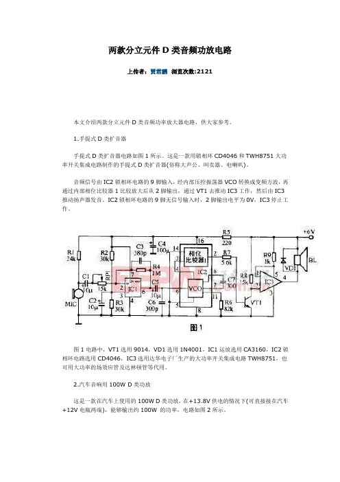
1.手提式D类扩音器手提式D类扩音器电路如图1所示。
这是一款用锁相环CD4046和TWH8751大功率开关集成电路制作的手提式D类扩音器(俗称大声公、叫卖器、电喇叭)。
音频信号由IC2锁相环电路的9脚输入,经内部压控振荡器VCO转换成变频方波,再通过内部相位比较器1比较放大后从2脚输出,通过VT1去推动IC3工作,然后由IC3推动扬声器发音。
IC2锁相环电路的9脚无信号输入时,2脚输出电平为0V,IC3停止工作。
图1电路中,VT1选用9014,VD1选用1N4001,IC1运放选用CA3160,IC2锁相环电路选用CD4046,IC3选用达华电子厂生产的大功率开关集成电路TWH8751,也可用大功率的场效应管及达林顿管等代用。
2.汽车音响用100W D类功放这是一款在汽车上使用的100W D类功放,在+13.8V供电的情况下(可直接接在汽车+12V电瓶两端),能够输出约100W 的功率,电路如图2所示。
在图2电路中,音频信号通过一个470nF电容耦合到双D触发器CD4013(IC1)的输入端,经过CD4013内部电路处理后,从Q、Q端输出两个含有音频成分的极性相反的信号,这两个极性相反的信号经过高速MOSFET驱动电路TC4426进行功率放大后,推动大功率MOSFET管IRFP140工作在开关状态,音频信号通过T2的耦合输出到扬声器中,推动扬声器发声。
图2电路在接阻抗为4~16Ω的扬声器时,均能正常工作,效率高于76%。
由于有输出变压器T2的存在,输出音色颇有胆机风味。
高速MOSFET驱动电路TC4426在4.5V~18V供电范围内均能稳定地工作,其输出驱动电流高达1.5A,而输出阻抗只有7Ω (内部电路如图3所示),因此是驱动MOSFET 功放管的理想器件。
由于该电路比较简单,很适合音响爱好者自制,故下面给出各元器件的参数,以便仿制。
提供通透清灵音频的全新超低功耗数模转换器

电话 :0 1 3 1 5 3 2 6 9 — 2 3
ht l t l p: www. y e s c r c pr s 。 o n
8 位可编程 电流限值及7 位可编程 过载电 流限值。一个 1 Hz 2 口允许主机 M 1 C接
控 制 器对 l 进 行 数 字 式 配 置 或 查 询端 口 C
提供通透清 灵音频 的全新超 低功
耗数模转换器
W 9 M8 以立体声接地参考耳机放 1 8 大器为特色 ,采 用了欧胜w类放大器和
一
优化的数据传输 卸载引擎( OE ,不仅 回兼 容 性 及 互操 作 性 。 口t ) 能将移动设备的I S ( OP 每秒输入/ 输出
运算次数 )吞 吐量 翻番 ,支持高 清视 频
ARM9 处理器内核 ,可让 器件充 当低功 可 实 现PS 与 PD的 相 互 识 别 并 为 PD提 E 耗音频协处理 器。
供 高 达 9 W 的 功 率 ,同 时 还 确 保 了 与 那 0
E PO 标 准 之 设 备 的返 E CYWB 2 3 H 控制器是一款高度 些 基 于 现 行 I EE 069 .  ̄
体 管 尺 寸 与 重 量 ,降 低 热 管 理 的成 本 ,
从 而 实 现 出 色 的 线 性 效 率 ( 传 统 解 e M M 4 4 等 最 新 海 量 存 储 标 准 ,从 9W 的功 率 。非 常 高 可 靠性 的P 比 0 D发 现 通 — C .x 决 方 案 高 6 % ) 。 此 外 , 该 器 件 运 行 而 能 够 实 现 更 快 的 数 据 存 取 以 及 更 大 的 过 运 用 一 种 专 有 的 双 模 式 、 4 检 测 机 0 A 时需要 的工作 电压 (8 2 V)大 于 Ga 存储容量 。此外 ,它还 具有赛普拉斯的 制 得 以 实 现 ,可确 保 最 优 的 抗 P 误 检 测 AS D M ES T (2 FE 1V) ,因此 晶体 管 还 支 持 全新E — tc特性 ,无须任何外部 电源 能 力。该PS 控制器提供 了高级 电源管 Z D et E
- 1、下载文档前请自行甄别文档内容的完整性,平台不提供额外的编辑、内容补充、找答案等附加服务。
- 2、"仅部分预览"的文档,不可在线预览部分如存在完整性等问题,可反馈申请退款(可完整预览的文档不适用该条件!)。
- 3、如文档侵犯您的权益,请联系客服反馈,我们会尽快为您处理(人工客服工作时间:9:00-18:30)。
YD8410
实物图:
芯片功能主要特性
5W/CH(5V 电源、2Ω 负载,10%THD) AB/D 类工作模式切换 宽电压工作: D类 (2.0V-5.2V) , AB 类 (2.0V-5.5V ) 低静态电流,低 THD,低 EMI 高效率(90%) 超低噪音,优异的上电掉电杂音抑制能力 短路保护、过热保护、过压保护 只需少量外围器件 采用 ESOP16
关断控制
为了提高效率,降低功耗,YD8410设计特别加入了关断控制功能(SHDN)。当控制脚输入为低电平时, YD8410就会关断内部的部份工作电流,如果把该管脚直接拉到GND时,YD8410就会处于最小供电流模式。该 功能不用时,可将该管脚悬空或拉高。默认为工作模式。
MUTE 控制
YD8410设有Mute脚静音功能,该管脚是用来对YD8410的输出进行控制的管脚,该脚处于低电平时关断输 出,高电平时允许输出。可通过该管脚瞬间关断YD8410的声音,达到静音功能,其静态电流参数参照上面的电 器性能表格。该功能不用时,可将该管脚悬空或拉高。默认为工作模式。
1.如果 YD8410 有接 LC 滤波电路时,应当先接上喇叭再上电,否则极易损坏芯片。 2.如果 YD8410 没有接 LC 滤波电路时,应当在输出端增加一个磁珠,以抑制电磁干扰。 3.YD8410 的最大工作电压为 5.5 V(AB 类) 、5.2V(D 类) 。如果 YD8410 要用 4 个电池供电时,建议不要使用 4 个全新的电池或者碱性电池,因为这样供电电压会超过 6V,高于 YD8410 的工作电压,极易损坏设备。因此 我们推荐使用 4 镍氢电池(镍氢)充电电池或三个干电池供电。 4.使用 YD8410 时,输入信号不应过大,大信号输入会导致输出信号出现削波失真,同时大信号大增益时将会 损坏芯片。 5.YD8410 没有接 LC 滤波电路时,如果用负载电阻代替喇叭作测试,测出的 THD 及效率都会比用喇叭时测试 的效果要差。因此,建议用喇叭进行测试。
供电退耦设计
YD8410是一款高性能的AB类/D类可切换式音频功率放大器,需要适当的电源退耦以确保它的高效率和低 谐波失真。退耦电容采用低阻抗陶瓷电容,容值为1μf,尽量靠近芯片电源 供电度引脚,因为电路中任何电阻, 电容和电感都可能影响到功率转换的效率。外围再加一个20μf或更大的电容放置在放大器的附近会得到更好的 滤波效果。
YD8410
单位 μA mΩ kHz mV
最小值 典型值 最大值 Vsd=0.3V <1
0.4 0.4
Байду номын сангаасV V °C
YD8410 典型参考特性
典型应用原理图
XZ-V1
7/11
CRT ELECTRONIC TECHNOLOGY LIMITED
操作说明:
YD8410
YD8410 是一款 5W(2Ω 负载)、AB/D 类可切换、 双通道高效音频功率放大器。具有低 THD+N、 高质量语音再生功能,具有低成本、外围电路简 单(极少外围元器件) ,占用面积小等特点。 YD8410 上电掉电杂音抑制能力强,音质优异, 效率高,功耗低,具有静音功能,非常适合便携 式产品的音频应用。
YD8410
电气工作特性
除特别说明外,环境温度 TA=25℃。 YD8410 电气特性表 1 参数 VIN 描述 供电电源电压 VDD=5.0V THD+N=10%,f=1kHz, RL=4Ω VDD=3.6V VDD=3.0V VDD=5.0V THD+N=1%,f=1kHz, RL=4Ω Po 输出功率 VDD=3.6V VDD=3.0V VDD=5.0V THD+N=10%,f=1kHz, RL=8Ω VDD=3.6V VDD=3.0V VDD=5.0V THD+N=1%,f=1kHz, RL=8Ω VDD=5.0V,Po=0.5W,RL=8Ω VDD=3.6V,Po=0.5W,RL=8Ω THD+N Gv 总失真度 增益 VDD=5.0V, 输入交流信号,以 Cin =0.47μF 接地 VDD=5V,Po=0.5W,RL=8 ,Gv=20dB VDD=5V, Vorms=1V,Gv=20dB VDD=5.0V, 输入交流信号,以 Cin =0.47μF 接地 VDD=5.0V, THD=1% RL=8 , THD=10% RL=4 , THD=10% VDD=5.0V,空载 IQ 静态电流 VDD=3.6V,空载 VDD=3.0V YD8410 电气特性表 2 参数 Imute
推荐工作条件
推荐工作条件表 参数 VCC 描述 工作电压 最小值 2.0 最大值 5.2(D 类) 5.5 (AB 类) 单位 V
XZ-V1
5/11
CRT ELECTRONIC TECHNOLOGY LIMITED
TA TC 工作环境温度 焊接环境温度 -40 -40 85 85 ℃ ℃
最大值
单位
5.2(D 类) V 5.5(AB 类)
W
W
W
VDD=3.6V VDD=3.0V
W % % dB dB dB dB μV dB % mA
VDD=5.0V,Po=1W,RL=4Ω VDD=3.6V,Po=1W,RL=4Ω
PSRR 电源电压抑制 比 Cs 串扰 SNR Vn Dyn η 信噪比 输出噪声电压 动态范围 效率
测试连接示意图
YD8410 测试连接示意图 注: 1. 在测试仪器与 YD8410 之间必需加一个低通滤波器。 2. 测量功放的输出功率时,最好在喇叭前串个 22μH 电感。
YD8410 应用说明
最大增益
由上功能框图可以看出,YD8410内部设有两级的放大,第一级增益可通过外置电阻进行配置,而第二级增 益是内部固定的。第一级的闭环增益可以通过Rf与Ri的比值进行设定,第二级的增益固定在了两倍。如此,第 一级的输出作为了第二级的输入,因此其放大效果上看与一级放大是一样的,但却有了180度的相移,因此我们 得出增益的运算公式为: A =20*lg [4*(Rf /Ri )] 注:又因为YD8410:RfMAX=88k,RiMIN=11k,因此,我们得出YD8410最大增益为30.1dB。
CRT ELECTRONIC TECHNOLOGY LIMITED
5W 立体声音大功率双模数字功放
YD8410
YD8410 用户手册
2012 年 7 月
XZ-V1
1/11
CRT ELECTRONIC TECHNOLOGY LIMITED
YD8410
芯片功能说明
YD8410
典型应用电路
XZ-V1
3/11
CRT ELECTRONIC TECHNOLOGY LIMITED
引脚分布图
YD8410
YD8410 ESOP-16 封装的管脚分布图
XZ-V1
4/11
CRT ELECTRONIC TECHNOLOGY LIMITED
YD8410 原理框图
芯片的基本应用
扩音器 便携式 DVD 播放器 便携式扬声器 多媒体监视器
XZ-V1
2/11
CRT ELECTRONIC TECHNOLOGY LIMITED
芯片订购信息
芯片型号 YD8410 封装类型 ESOP16 包装类型 管装 最小包装数量(PCS) 50/管 备注
描述 静音模式电流
条件 VDD=5.0V
VMUTE
最小值 典型值 最大值 3.5
单位 mA
6/11
CRT ELECTRONIC TECHNOLOGY LIMITED
参数 ISD Rdson fsw Vos VIH VIL VIH VIL OTP OTH 开关频率 输出偏置电压 启动输入电压(高电平) 启动输入电压(低电平) MUTE 输入电压(高电平) MUTE 输入电压(低电平) 过热保护 过温迟滞 描述 关断电流 条件 VDD=2.0V to 5.5V IDS =500mA,Vgs=5V VDD=3V to 5V Vin=0V, VDD=5V VDD=5.0V VDD=5.0V VDD=5.0V VDD=5.0V 无负载,节点温度 VDD=5V 1.5 1.5 PMOS NMOS 180 140 300 10 1.4 0.7 1.4 0.7 140 30
AB/D类模式切换
YD8410设有Mode引脚,该管脚是用来对YD8410的模式进行选择的管脚,该脚处于高电平时,进入AB类 工作模式;低电平时,选择D类工作模式;默认为D类。 YD8410可以在AB类和D类这两种工作模式之间进行自由切换,以下是采用AB类与D类优缺点分析比较: AB 类音频放大器的效率只有 25%左右,能耗大;D 类具有高达 90%的效率。D 类技术的效率会被更加重
XZ-V1
8/11
CRT ELECTRONIC TECHNOLOGY LIMITED
YD8410
视 应用场合多,如在日愈丰富的多媒体数码内容更多是 MP3 音乐、影音片段和数字电视 AB 类技术的音频性能好,THD+N 低,PSRR 的绝对数值高。此外,AB 类的应用中没有噼啪声和咔嗒声, 噪声很小,而且开启时间和关闭时间都很短,亦可实现节能的方案。D 类的工作模式完全不同于 AB 类,会产 生某些高频谐波--- EMI 干扰。 在小功率音频驱动中,比如音频耳机功放对效率和功率的要求不高,或者 Hi-Fi 耳机放大器对失真率有较 高的要求,此时 AB 类功放的超低失真率就体现出了优势,如今在耳机放大器的设计中 AB 类仍是唯一的选择; AB 类技术的音频性能好,THD+N 低,PSRR 的绝对数值高。 小型化趋势对降低 D 类音频放大器的噪声带来了限制。 D 类音频放大器的成本一般是 AB 类的 2 至 3 倍,尽管 D 类提供较佳的功效及散热能力。 与简单的 D 类取代 AB 类不同,源达科技公司采用了兼容方案,在没有射频发射/传输的时候,运行 D 类模式; 在射频发射/传输的时候,运行 AB 类模式,充分利用 D 类和 AB 类的优点,弥补各自缺点。