绿色紧凑型功率因数控制器MC33260
新能源汽车电源充电机DCDC三合一_技术条件要求(详细标准车规级)

三合一控制器总成(CDU)技术需求文档项目名称:XX项目整车型号:XXX编制:会签:校对:审核:批准:XXX研究院三电部技术要求一、零部件清单及结构明细所有材料由乙方根据产品的设计、性能要求和寿命要求来决定具体材料的选择。
乙方应标明零部件中所使用的可回收的材料,并标出塑料零件、橡胶零件及热缩性弹性体零件可再循环利用的鉴别标志。
所有材料应该满足国内外报废汽车回收相关法规标准(报废汽车指令2000/53/EC 和车辆再使用、再利用和再回收利用型式认证指令2005/64/EC)、中国国标(GB/T 30512-2014 汽车禁用物质要求)相关要求。
CDU系统所采用的塑料件应不含卤素、其阻燃等级应达到UL94 V0 级。
二、具体要求2.1高压配电模块技术要求2.1.1概述高压配电模块将动力电池的高压直流电,分配给电动压缩机、DCDC、PTC1和PTC2,将车载充电机或充电桩输出的电能输送到动力电池,并且在必要回路提供线路保护,系统架构如下图所示:图1 高配高压系统架构图2.1.2功能要求部分连接器应有防接错措施,其中车载电源总成,要求所有连接器正负极性接线正确无误,具体应用情况由甲、乙双方协商确定;回路保护方面,a)OBC及DCDC回路使用规格为40A的熔断器;b)电动压缩机和空调PTC回路使用规格为80A的熔断器。
如果熔断器的规格需要调整,需由甲、乙双方共同协商确定。
回路开断控制方面,为空调PTC回路提供两个高压继电器,用于控制PTC两档工作,继电器分别位于回路1正极20A(采用SCII EV20)和回路2正极40A(采用SCII EV40)。
如果继电器的规格需要调整,需由甲、乙双方共同协商确定。
为整车高压用电设备及充电设备提供高压接口,同时提供方便高压系统检修的接口。
2.1.3信号接口型号定义(低压信号):图3 信号接口MC3336A850-PP-CT006引脚定义2.1.4高压接口型号定义:表1:接插件型号:位置位置说明插座型号插头型号厂家电池接口BAT+,BAT- / / /PTC接口PTC1+,PTC1-;PTC2+,PTC2-/ / /压缩机接口A/C+,A/C- / / / 交流输入壳体上标注ACDC12+输出壳体上标注DC+低压信号接口壳体上标注SIGNAL接口类型接口形式接口型号图示接口规格DCDC正极极座标准/ M8-16(铜鼻子端子)表3-2:插接件接口定义2.1.5性能要求1、高压配电模块性能要求2、电缆及连接器3、低压接插件要求具体要求如下:1)接插件插合后防护等级为IP67。
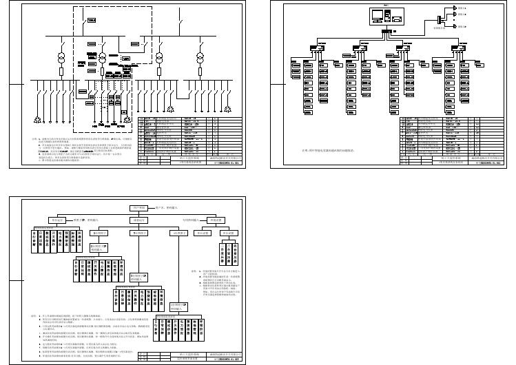
变压器监控系统图-变压器监控系统图
MC33262P中文资料

BLR-CX电力因数调节器操作和启动手册说明书
BELUK GmbH ! D-86956 Schongau ! GermanyTaubenstr. 1 " Tel. ++49 8861 2332-0 " Fax ++49 8861 2332-22e-mail: - http://www.beluk.deOperating and Commissioning Instruction for BLR-CXContents:page2 Installationpage2EquipmentsControl4 Commissioning page6pageAlarmFunctions6pageTransmissionData8Diagram pageConnectionOptional FeaturesFan Control incl. H/L-Tariff selecting page 6Fan Control dependent on temperaturefor Power Factor Target change over page 7Indication of measuring Values page 7InstallationAs with all electrical equipment, the appropriate specifications governing electrical installation must be followed when power factor correction equipment is installed. When removing the front nameplate to adjust the function switch and DIP switches, always ensure that your body is not carrying any electrostatic charge. This can be accomplished by simply touching an earthed object, such as the switchboard metal casing to dissipate any electrical charge before removing the cover plate.1 Check that the measurement and control voltage, supply frequency and current transformer rating comply with theratings given on the back of the relay.2 Mount the relay in the switch panelby means of two fixing bolts3 Connect up in accordance with the wiring diagram. Pay special attention to the cross section size of the C.T.connections. We recommend for runs up to 10 metres 2,5 mm2 cross section. An integrated voltageobservation with regard to the supply voltage in BLR-CX guarantees a safety-disconnection of the capacitors incase of excess voltage < 70 % of mains voltage. It must be ensured, that supply voltage is taken from the identical phase as control voltage for the contactors. Please use specified tool for wiring into the spring terminals. Steelcover on the rear of the relay must be earthed.4 Current path of the regulator is designed for current transformers either for5 A or 1 A secondary coil as well.Selectable c.t. ratio up to 4000 max. C.t.-ratio setting is only possible for regulators with option M, excludingly(Regulators with additional energy data indications).Control EquipmentsBehind the removable nameplate there are a multifunction switch (H3) and 2 pushbuttons (+/-) available.At option “L” (fan control) there are 2 additional DIP switches (S1/S2) fitted for selecting 4 temperature threshold levels.At option “M” (Multimeter Functions) 2 additional keys are integrated on front facia for polling off data.Selecting regulators parameter will be done by means of the +/- pushbuttons with reference to the preselected step of the multifunction switch (H3). Preselected parameters ex work facilitates commissioning the regulatorAll regulators are preset at the multifunction switch (H3) to the following parameter es work:Multifunction Switch (H3)0 Any control out of order. Energized steps, if any, will be disconnected after 20 sec. automatically. Selecting ofa threshold level in the range of 10….60 % with reference to the recorded first value of each capacitor step(equal 100 %) at commission of the plant. Preset value ex work: 50 %. Display indicates “OFF” alternating with “50”1 p.f. target set, selectable in the range of 0,70 lag …1…0,90 lead;preset to cos ϕ = 1,002 Switching time delay, selectabel from 5 sec ... 1200 sec. Pushing button + or – for longer than 2 sec. enables rapidselection.Preset delay ex work: 40 sec.3 Fully automatic control of compensation plant. Display indicates the current power factor with either I forinductive or c for capacitive load (reprinted each 3 sec.) A flashing dot in display above the signs either + or –signals, that the regulator is selecting a suitable capacitor, if available, with regard to the reactive power deviation current cos ϕ indication each 3 sec.Energy data available with option M excludingly.operation4 ManualManual operation is possible with measuring voltage > 50 V, excludingly, by alternating pushing either the + or the – button, steps will be activated or deactivated, respectively, to the preset switching time delay in position 2,accordingly. Letter H will be displayed alternating with the current p.f. (1 sec/ 5 sec)5 Selection of Step LimitationStep limitation in accordance to the available outputs referring to type of relay CX 04, CX 06, CX 08 or CX 12.Limitation will be displayed e.g. “CL 12”. Do not exceed the max. available outputs as far as alarm will betriggered.6 Automatic display of failed CapacitorsIndication of either failed capacitor steps or unengaged outputs. Indication of e.g. “Cd 05” alternating with “Cd 09” indicates, that steps 5 and 9 are failing. “Alarm” (AL_ _) will be triggered synchronously. To reset any alarm press button + and – for longer than 20 sec. “Cd 0” signals, that no step fails. Automatic control is active all the time!7 The number of switchingThe number of switching operations per each contactor has made is shown in the display, e.g. “OC 4” for 2 sec., then “248”. This indicates, that contactor no. 4 has completed 248 switching operations. Other contactors can be selected by using the +/- buttons. Only every 10 switching operations the micro processor stores the data. The stored data of all steps can be cancelled by depressing the +/- buttons together for a time longer than 20 sec.Automatic control is active all the time!8 Indication of Step SizesThe value indicated on display is proportional to the step size, but not calculated in kvar, as far c.t.-ratio isunknown. It will be displayed e.g. “CC 10” for the 10th step, followed by 2 numbers e.g. “L 74” and “F 84”.Value “F” stands for the f irst sensed capacitor size during commissioning and “L” for the l ast value after, let´s say several months or years. This is to recognize loss of capacity, if any. If the selected threshold level in pos. 0, will be decreased due to failed capacitor or blown up fuses, the regulator eliminates this step from control procedure and triggers alarm “AL”, shown in display. The data per each step may be polled off by means of either + or – button.To reset the stored data enables by pushing both buttons + and – together for longer than 20 sec. The regulator starts to come to know each step from the very beginning. Automatic mode is still active in the background.CX-regulators fitted with option “M” (Indication of energy data) displays the sensed capacitor sizes in real kvar at correct c.t. setting (see page 5).9 Selecting Mode of AlarmSelection by means of the push buttons +/-.Any alarm function is deactivated in selecting “A__0”, no alarm indication will appear. Automatic reset of any triggered alarm if, e.g. the regulator is able to achieve the preset power factor target again or after any change of switching direction, up/down, in selecting “A__1”.Once a triggered alarm will be stored until any manual confirmation in selecting “A__2”.Reset possible with “A__3”, excludingly.To reset any triggered alarm, caused either by control procedure (triggered by passing 75 times preset switching time delay) or by temperature, enables in selecting “A__3” and pushing button + longer than 5 sec. It will be confirmed by “ArES” in display. Afterwards select requested alarm mode again. Any triggered alarm, caused by failed steps, is ressettable in position 6 of the multifunction switch (H3), excludingly,at preset alarm mode “A__2”.(“AL” will be displayed in case of any triggered alarm).A Selection of a 2nd Power Factor TargetOption “L” 2nd p.f. target will be activated by signal voltage 150-240 V AC on terminals NT/NT1.Option “LT” 2nd p.f. target will be activated automatically in case of temperature will exceed 57° CB Selection of an asymmetrical Switching Time Delay.Selectable range of an asymmetric factor: 1…99 by means of pushing the button + or -. Displaying e.g. “Y_10”multiplies the preselected switching time (pos. 2) with factor 10 for disconnecting steps (rapid in, slow out; slow in, rapid out on request). Preset factor ex word = “1”, means symmetrical switching time delay for both directions.C Selection of a Lock Time at each Change of Switching Direction up/downAn included variable load reversal lock-out time is activated when switching direction changes from “up” to“down” or conversely. Displaying e.g. “L_30” means a lock time of 30 sec. becomes effective. This lock time will be added to the preset switching time delay ex pos. 2. This enables to reduce the switching operations at rapid changing loads. Selectable range of lock time = 1…254 sec.;preset time ex work: 30 sec.D Selection of C.T.Ratio (only adjustable with option “M”)“_not”DisplayindicatesE Selection of V.T. Ratio (only adjustable with option “M”)“_not”indicateDisplayF Selection of Switching Program by means of pushing button + or -.After any amendment re-energize the regulator (brief interruption of supply voltage)Displaying “Auto”: Fully automatic recognition of each capacitor size without fixed program intelligent selection of the suitable capacitor to achieve the preset power factor target with the minimum of switching operations.2-phase connection L2/L3.Displaying “1 1 1 1”: Fully automatic recognition of each capacitor size. Linear switching program up 1….12 and down 12….0 means FILO/LIFO (first in last out / last in first out). 2-phase connection L2/L3.Displaying “Eaut”: identical to “Auto”, however 1-phase connection L1/NDisplaying “E111”: identical to “1111”, however 1-phase connection L1/NPreset ex work: “Auto”Commissioning1 Apply the supply-, measurement- and control-voltages. Connect the current transformer, and remove any shortcircuit link. If measurement voltage is taken from 1 phase against neutral modification must be ensured in positionF of the multifunction switch (H3) followed by a voltage reset of the supply voltage.Indication “I—O” : no current flowing, resp.: <10 mA of secondary c.t. current. If any capacitors had beenenergized before, these steps will be disconnected at once after 5 minutes (possible at parallel operation of capacitor banks). If regulator is set to manual mode, any energized steps “stand by” all the time.Indication “U—0” measuring voltage is below 50 V or not connected.Regulator will start to control, if measuring-voltage is 50 V and reactive component of current 10 mA at least.If measuring voltage decreases below 50 V any energized steps will be switched off at once after delay of 2 sec.indipendent on either automatic or manual mode.2 Ex work preset parameters are:Power factor target = 1; switching time delay 40 sec.; step limitation to regulator´s maximum; alarm mode = 1;asymmetrical switching time factor = 1; load reversal lock tim = 30 sec.; c.t.-ratio = 100; v.t.-ratio = 1.0; switching mode = Auto with 2-phase measuring voltage L2/L3. Any modifications, if requested, may be done viamultifunction switch (H3) and push buttons + or -, as described. Amendments of parameters will be indicated on display.Attention: c.t.-ratio and v.t.-ratio exclusive adjustable with option “M”!The selected parameters will be stored in the regulator, if multifunction switch will be set back into pos. 3again, only.3 Ensure, that multifunction switch (H3) is set to pos. 3 (Automatic mode)4 No volt release lock time of 90 sec. must be passed, before regulator starts to control. During this period steps willnot be activated.5 Check preset power factor target in pos. 1 and select, if requested.6 Check preset switching time delay pos. 2 and select, if requested.7 Check preset step limitation and adapt to the real number of connected capacitors in pos. 5. If any control output ofthe regulator remains unengaged, it will be recognized. The regulator tests each free output 3 times to ensure it isunengaged and will lock this step for 1 day at least, until a voltage interruption or after reset of “CD” in pos.6. Then these steps will be checked again 3 times each. If there are still “failed steps” detected, they will be recorded in pos. 6;alarm will be triggered.8 Check preset alarm mode and select in pos. 9, if requested.9 Set back the multifunction switch into pos. 3.10 Display indicates the current power factor cos phi e.g. “i 0.87” for inductive or “c 0.94” for capacitive load.11 At correct wiring after the no volt release lock time and inductive load a dot in the display at sign “+” will flash.12 The regulator starts to energize step by step in the rhythm of selected switching time delay in order to achieve thepower factor target. LED`s signal activated steps. Each step must influence the current cos phi. Is there a digitaldeviation of the current power factor compaired with the target, dot at sign “+” will flash in case of p.f. is below or dot at sign “-“ will flash in case of p.f. is above the target.13 At BLR-CX it is not necessary to preset any C/k-value (threshold level when to start to switch in/out a step), as farthe step sizes will be sensed automatically. The regulator does not follow up a fixed switching program; it willselect a suitable capacitor, if recorded already, in order to achieve the target. During the daily routine all capacitors will be stored with regard to its size in numbers proportional to the capacitance (see pos. 8 of H3). There is noindication in kvar , as far the c.t. is unknown. (Exception at option M). At use of equal sized capacitors theregulator distributes the switching operations equally to the capacitors as much as possible. For special applications there is a fixed switching program available in the ratio 1:1:1….:1 in pos. F of H3.14 It may happen, that one of the dot + or – are flashing steadily and the regulator will not switch on/off any step asfar it is not able to find a suitable step size with reference to the deviation from the target p.f. If p.f. is digitalidentical with the target, no dot is flashing.15 In case of no existing load a first check of the capacitor bank may be possible in manual mode in pos. 4 at themultifunction switch (H3) by using push button + for switching on capacitors. Ensure, that measuring voltage is >50 V AC. In this mode there is no automatic sensing of the step sizes given. Returning back to pos. 3 then theregulator must disconnect all steps automatically; in this mode the regulator is able to recognize the sizes,excludingly (see item 13).Once the required settings or alterations have been made, set function switch (H3) to position 3 “automatic” and replace the front cover plate, so as to inhibit unauthorized interference with relaysettings.Alarm Functions1 Power Factor Alarm (Display shows: “AL”)If the predetermined power factor is not abtained in case of insufficient capacitance, the alarm signal is triggeredafter elapse of 75 x the selected step switching time, valid for both directions lead and lag. If the set target p.f. isstill surpassed due to overcompensation (welded contacts) after elapse of 75 x the selected step switching time, this alarm will be triggered, “AL” displayed. To reset any triggered alarm will be possible in pos. 9 of the multifunction switch (H3) in mode A__3 (see item 9, page 3)2 Alarm will be triggered as well, if the regulator has detected failed step(s). “AL_ _” will be displayed alternatingwith other functions (cos phi) each 5 sec. Reset is possible in pos. 6 of H3 (see page 2).3 If supply voltage fails, there is no indication in display, contact at terminalsM – MO will close and M – MS opens for external use; switching rate: 3 A at 250 V ACData TransmissionBELUK-software “WINBSTO” enables to indicate and recording of power factor, operation cycles, any triggered alarm, signed with clock and date on PC for purposes of analysis. Each switching operation of the regulator are accompanied with 2 telegrams via TTL-interface (14-pole plug on the rear of casing), one before and one after switching procedure. This enables to analyze the compensation effect per each step with regard to the influence of the power factor. Storing data on PC requests a data cable with integrated converter TTL/RS232 for transmitting the data to the PC (extra equipment- length 0,2 m – No.8). Furtheron it is possible to store data with data logger “DS 21, 22 or 23” locally at the capacitor plant within a defined period of time. Afterwards the data logger could be taken along for reading out data on PC with the help of a word program. Optional FeaturesOption “L” contents 2 functions:Control1 FanIn case of increasing the preset temperature threshold level the regulator displays “HA” alternating withadditional indications in the rhythm of 5 sec. For purposes of controlling a fan an output relay closes atterminal LF/LF1(switching rate 5 A at 250 V AC). Any reset follows automatically in case of decreasedtemperature after a “time window” of 8 min. or manually in pos. 9 of the multifunction switch (H3) inselecting mode “A__3” (see page 3). So the fan will be switched on/off 8 min. at least.Behind the removable name plate there are 2 DIP switches located for preselecting 4 different temperaturethreshold levels as shown below:If both alarms, power factor and temperature had been triggered, display indicates “AH”; both output relayswill be activated. Reset is possible as described above.In case of any triggered alarme, referring to p.f. control, during fan is cooling the display indicates “AH” .Both alarme relays will be activated; any reset is possible as described for each alarme relay, individually.Temperature 20° 25° 30° 35°S1 OFF ON OFF ONDIPS2 OFF OFF ON ONDIP2 2nd Power Factor Target (High/Low Tariff)As described in pos “A” of the multifunction switch (H3), there is a second power factor target in the range of0,70 lag….1….0,90 lead selectable which may be activated via e.g. an external clock switching on a voltageonto the terminals “NT/NT1” (150….240 V / 45….65 cps) during low tariff period. If this voltage is notsupplied, the regulator controls with reference to the 1st power factor target (high tariff), selected in pos. 1 ofthe multifunction switch (H3), accordingly.Option “LT”:This implies option “L” automatically (see item 1). After exceeding the temperature threshold level of 57° the 2nd power factor target will be activated (hysteresis 4°)Nange over onto a 2 an powerfactor target via double-tariff control is impossible (s.item 2).Option “M”Regulators with this option are fitted with a modified facia contenting 2 pushing keys signed + and -; they replace the former push buttons behind the name plate. This option requests the setting of a c.t.-ratio in order to get correct indication of energy data in display. At big plants an automatical change of scale from e.g. kW to MW is provided, means indication changes from 9999 kW to 10.0 MW. Any indication will be overwritten each 3 sec.In the pos. D and E of the multifunction switch (H3) c.t.- and v.t.-ratio must be preset:D = c.t.-ratio:By using key + or – in the range of 1….4000 (e.g. 800A/5A =160)preset ex work 100, pushing key longer 2 sec. enables rapid selection.E = v.t.-ratio:By using key + or – in the range of 1.0….350.0 (e.g. 20 kV/0,1kV =200)preset ex work 1.0, pushing key longer 2 sec. enables rapid selection.CX..M indicates following energy data selectable by using key + or -:FactorC PowerU MeasuringvoltageI Current of the sensed phaseP Total active PowerPowerapparentS Totalq Total reactive PowerF FrequencyOption “k”Combi Filter Switching ProgramIt must be ensured, that at combi filter banks the numbers of energized steps with higher choke ratio (e.g. 12 %) are more than with the lower choke ratio (e.g. 7 %)For this purpose there is the switching program “Combifilter” available. It must be mentioned in purchase order for providing ex work.Furtheron it must be ensured, that the higher choked steps are connected to the odd and the lower choked steps the even outputs of the regulator.。
部分电源输入级电路
*
*
从上图可以看出,电流和电压的相位及形状都极为相似。各次谐波含量都非常的小。
带有源功率因数校正的电源系统输入电流电压的波形如下左图,相应的谐波含量的成分如下右图:
用控制芯片MC33260(安森美)的PFC电路如下图:
4.浪涌电流---产生及其抑制的方法 输入交流电压的任意时刻通过开关管的控制传递能量给负载,电路刚开始启动工作时,大的储能电容相当于短路,如果在输入电压的峰值给电容充电,就会产生一个很大的电流,该浪涌电流可能是额定情况下系统峰值电流的20~1000倍,可能对储能电容、整流器和功率开关管造成破坏性影响。
抑制浪涌电流的几种方法:
*
在输入端直接串联热敏电阻(负温度系数),如下图所示:
*
(2) 在PFC的输出端串联热敏电阻,如下图所示:
(3)PFC输出储能电容上串联一个电阻//MOS管,如下图
(3) 输入储能电容特性
*
*
2.射频干扰抑制---EMI滤波器和安规事项
产生干扰信号的原因:开关电源在工作过程中会产生很多噪声及谐波,比如整流桥+大电容滤波储能时,输入电流是很窄的矩形脉冲,这种波形的谐波含量非常大;另外,PCB以及隔离变压器的匝间电容或者寄生的电感等引起的干扰信号。
抑制干扰信号:采用EMI滤波器来抑制干扰信号,使设备正常工作,使谐波含量满足欧洲的EN61000-3-2标准。 常用的EMI滤波器结构如下图:
117V输入全波整流倍压电容滤波电路如下图:
如输入电压在117V±15%时,经过整流滤波之后如何得到300V±20%的直流电压? 因为直流变换器是根据正常输入直流电压为300V设计的。
全波倍压整流滤波电路图及两种整流方法的输出波形: 电阻的作用是使电压在两个电容上平均分配。 全波倍压整流滤波电路也可以应用到辅助电源Vcc中。如下电路
DOLD多德产品
E. Dold & Söhne KG 多德电气多德电气((太仓太仓))有限公司1928年,Emil Dold 先生创建了DOLD (E. Dold & Söhne KG )公司,发展至今,在全球已有超500多名员工,是继电器领域的先驱者,是世界领先的专业继电器制造商。
基本信息栏 中文名: 多德 外文名: DOLD总部地点:德国福特万根市 成立时间:1928年目录产品 (4)1.继电器模块 (4)1.1安全模块 (4)1.2监控模块 (6)1.3功率电子模块 (7)1.4控制模块 (8)1.5楼宇自动化模块 (9)2.安全联动锁 (10)3.线路板继电器 (11)4.导轨式外壳 (13)产品1.继电器模块 1.1安全模块急停模块单通道双通道 带延时功能 ..安全门监控模块标准型 BD5985N 带矛盾控制 BN5986 安全开关带触点输出 NE5021 带半导体输出 NE5020用于安全开关组的控制单元 BG5925/920光幕/光栅控制模块标准型, LG5925/900带muting功能, BH5902 /01MF2双手控制模块BD5980NLG/BG/BH 5933安全地毯BG5925/920扩展模块\延时模块:用来扩展安全模块的输出触点LG/BG 5929,BN3081,UG6929, BG7925, BG7926速度\停机监控BH5932,UH5947BD5936, LH5946多功能安全监控:急停,安全门,光幕 .BH5910,BH5911无线安全模块RE 5910SAFEMASTER PRO 安全PLC1.2监控模块绝缘监控IL5880 ,MK5880N,RP5888,UP5862IL5881,SL5881,AN5892/800 直流系统 AN5873,AN5890 交直流系统剩余电流监控(接地系统) IL5882/SL5882 (交流,脉动直流) IP5883(交流,直流,)测量模块:过欠电压\电流,相序,功率因数,功率故障报警器1.3功率电子模块固态继电器\接触器软启动电机刹车模块固态换相接触器(电机正反转)简单的速度控制器多功能电机控制1.4控制模块总线控制CANOpen PLCIL5504接口继电器标准型, IK3070带主动导引触点型插拔型, OA5630, OA1.5楼宇自动化模块远程控制开关模块遥控开关IK8702, IK8717中央开关IK8703中央开关和开关组IK8805特定模块优先开关继电器IK8715步进开关继电器IK8831时间控制开关楼梯通道时间继电器IK8810带预警功能型IK8810/002节能型IK8810/004风扇控制时间继电器IK8810/0052.安全联动锁多德STS 安全联动锁系统是根据DIN EN ISO 13849标准设计,并通过TÜV 安全认证,STS 安全联动锁集安全开关,电磁锁和联动钥匙系统为一体。
AC-DC LED驱动器功能表说明书

AC-DC LED Lighting DriverPower Number Function Package Integrate d FETs Max Power Dimming Vin Range PFC Isolation Opto-coupler Open/Short LED Protection PeakEfficiency Typical Applications SY58004Flyback SO8500V 14W NO 110V YES NO NO YES 91%Tube/PAR/Down Light/Bulb SY58102Flyback SO8600V 9.5W NO AC LINE YES NO NO YES 87%Tube/PAR/Down Light/Bulb SY58103Flyback SO8600V 11W NO AC LINE YES NO NO YES 87%Tube/PAR/Down Light/Bulb SY58200Flyback SO8700V 3W NO AC LINE YES NO NO YES 80%Tube/PAR/Down Light/Bulb SY58201Flyback SO8700V 5W NO AC LINE YES NO NO YES 80%Tube/PAR/Down Light/Bulb SY58202Flyback SO8700V 8W NO AC LINE YES NO NO YES 87%Tube/PAR/Down Light/Bulb SY58203Flyback SO8700V 10W NO AC LINE YES NO NO YES 87%Tube/PAR/Down Light/Bulb SY58241Buck PFC,High Side Switch SO8500V 9W NO AC LINE YES NO NO YES 85%Tube/PAR/Down Light/Bulb SY58242Buck PFC,High Side Switch SO8500V 12W NO AC LINE YES NO NO YES 90%Tube/PAR/Down Light/Bulb SY58243/A Buck PFC,High Side Switch SO8500V 15W NO AC LINE YES NO NO YES 86%Tube/PAR/Down Light/Bulb SY58244Buck PFC,High Side Switch SO8500V 19W NO AC LINE YES NO NO YES 92%Tube/PAR/Down Light/Bulb SY58291Buck PFC,Low Side Switch SO8500V 9W NO AC LINE YES NO NO YES 90%Tube/PAR/Down Light/Bulb SY58292Buck PFC,Low Side Switch SO8500V 12W NO AC LINE YES NO NO YES 90%Tube/PAR/Down Light/Bulb SY58293/A Buck PFC,Low Side Switch SO8500V 10W NO AC LINE YES NO NO YES 87%Tube/PAR/Down Light/Bulb SY58294/A Buck PFC,Low Side Switch SO8500V 15W NO AC LINE YES NO NO YES 92%Tube/PAR/Down Light/Bulb SY58541Buck PFC,High Side Switch SO8600V 7.5W NO AC LINE YES NO NO YES 87%Tube/PAR/Down Light/Bulb SY58542Buck PFC,High Side Switch SO8600V 10W NO AC LINE YES NO NO YES 89%Tube/PAR/Down Light/Bulb SY58543/A Buck PFC,High Side Switch SO8600V 10W NO AC LINE YES NO NO YES 85%Tube/PAR/Down Light/Bulb SY58544Buck PFC,High Side Switch SO8600V 15W NO AC LINE YES NO NO YES 91%Tube/PAR/Down Light/Bulb SY58591Buck PFC,Low Side Switch SO8600V 7.5W NO AC LINE YES NO NO YES 91%Tube/PAR/Down Light/Bulb SY58592Buck PFC,Low Side Switch SO8600V 10W NO AC LINE YES NO NO YES 90%Tube/PAR/Down Light/Bulb SY58593/A Buck PFC,Low Side Switch SO8600V 13.5NO AC LINE YES NO NO YES 89%Tube/PAR/Down Light/Bulb SY58594/ABuck PFC,Low Side SwitchSO8600V16WNOAC LINEYESNONOYES91%Tube/PAR/Down Light/BulbAC-DC Primary Side ControllerPower Number Package PFC Opto-couplerQR Mode Green ModeSY5011SO8YES YES YES YES SY5012SOT23-6YESYESYESYESSY5013SO8NO YES YES YESGreen Mode Flyback PFC Controller With Primary side CC Limit and Opto-feedback for CV RegulationYESYES Selection GuideE-Mail:*******************联系人:邵生 135******** QQ:645950091Constant OutputVoltageFunctionYES SILICON ENERGY----Powering the FutureGreen Mode Flyback Ciontroller With Primary Side CV/CC Control YES YESNO Constant Output VoltagePSRGreen Mode Flyback CiontrollerWith Primary Side CV/CC ControlLED Lighting DriverPower NumberFunction Vin(V)Vsw,max(V)Isw,max(A)Fsw (MHz)Vref (V)Syn Switch Ron в(m Ω)Main SwitchRon (m Ω)PackageSpecial FunctionSY8702Step Down 2.5~30300.810.1NA 200SOT23-6PWM Dimming SY8703Step Down 2.5~3030 1.310.1NA 200SOT23-6PWM Dimming SY8006Step Down 2.5~5.56 2.4 1.50.1150200SOT23-5Int ss/CompSY8710Step UP/Down 3~3030210.1NA 200SOT23-6Analog Dimming SY8711Step UP/Down3~3030210.1NA 200SO8/EAnalog DimmingPower Number Package Dimmi ng Vin Range PFC Isolation Opto-coupler QR Mode SY5800A/D SO8NO AC LINE YES YES NO YES SY5801A SO8TriacAC LINENO YES NO YES SY5802/A SO8PWM/Analog AC LINEYES YES NO YES SY5803SO8NO AC LINE YES NO NO YES SY5804SO8NO AC LINE YES NO NO YES SY5804A/A1SO8NO AC LINE YES NO NO YES SY5810/B/D SOT23-6NO AC LINE YES YES NO YES SY5813SOT23-6NO AC LINE YES NO NO YES SY5814SOT23-6NO AC LINE YES NO NO YES SY5814A SOT23-6NO AC LINE YES NO NO YES SY5819SOT23-6NOAC LINEYESNONOYES24V BUS Street Lamp,MR16E-Mail:*******************联系人:邵生 135******** QQ:64595009124V BUS Street Lamp,MR16Selection GuideTypical ApplicationsSILICON ENERGY----Powering the FuturePortable Torch/Flash/HeadlingLampGPS, MID GPS, MIDFunctionSingle Stage Flyback PFC Controller With Primary SideControl Single Stage Flyback PFC Controller With Primary SideRegulation and Traic dimming Single Stage Flyback PFC Controller With Primary SideRegulation and PWM/Analog dimmingSingle stage Buck-Boost PFC controller Single Stage Buck PFC Controller(Floating Switch)Single Stage Buck PFC Controller(Grounded Switch)Single Stage Buck PFC Controller(Grounded Switch)Single Stage Floating Buck PFC Controller(FloatingSwitch)Single Stage Buck PFC Controller(Floating Switch)Single Stage Floating Buck PFC Controller with PrimmarySide ControlSingle Stage Buck-Boost PFC controller。
艾顿公司产品:2路电压接触器类型AFDD+防炸性防护设备说明书

Protective DevicesArc Fault Detection Device AFDD+,Catalog1.1Protective DevicesArc Fault Detection Device AFDD +, 2-pole• A rc Fault Detection Device acc. to IEC/EN-62606• D etects and quenches arc faults in final circuits• F ully combined with residual current circuit breaker (RCCB) and miniature circuit breaker (MCB)• 2-pole: Both clearances between open contacts are protected• V ariable installation of N either to the left or right• R ated currents from 6 to 40 A • C ontact position indicator red – green • T ripped indication: MCB, RCCB or AFDD • L ED indication for arc faults • P ermanent self-monitoring • O vervoltage and overheat monitoring • G uide for secure terminal connection • 3-position DIN rail clip, permits removal from existing busbar system• C omprehensive range of accessories suitable for subsequent installation • 10 and 30 mA rated residual currents • T ripping characteristics B, C • R ated breaking capacity up to 10 kA • T he -OL types are specifically designed to fullfill the tripping characteristic requirements of I 2 ≤ I z in the Norwegian electrotechnical standard NEK 400-8-823.Descriptionsg064161.2Protective DevicesArc Fault Detection Device AFDD+, 2-poleType F, 10 kA, 2-poleSurge current-proof 3 kA, sensitive to residual pulsating DC, type Fsg0641610OL/0.03AFDD-10/2/B/003-F-OL MB-3001841/4013OL/0.03AFDD-13/2/B/003-F-OL MB-3001851/4015OL/0.03AFDD-15/2/B/003-F-OL MB-3001861/4020OL/0.03AFDD-20/2/B/003-F-OL MB-3001871/4010/0.03AFDD-10/2/B/003-F1872431/4013/0.03AFDD-13/2/B/003-F1872531/4016/0.03AFDD-16/2/B/003-F1872631/4020/0.03AFDD-20/2/B/003-F1872721/4025/0.03AFDD-25/2/B/003-F1872781/40I n/ID n(A)TypeDesignationArticle No.Units perpackage10OL/0.03AFDD-10/2/C/003-F-OL MB-3001791/4013OL/0.03AFDD-13/2/C/003-F-OL MB-3001801/4015OL/0.03AFDD-15/2/C/003-F-OL MB-3001811/4020OL/0.03AFDD-20/2/C/003-F-OL MB-3001821/406/0.03AFDD-6/2/C/003-F MB-3001781/4010/0.03AFDD-10/2/C/003-F1872491/4013/0.03AFDD-13/2/C/003-F1872591/4016/0.03AFDD-16/2/C/003-F1872691/4020/0.03AFDD-20/2/C/003-F1872751/4025/0.03AFDD-25/2/C/003-F1872811/40Characteristic CType F, 6 kA, 2-poleSurge current-proof 3 kA, sensitive to residual pulsating DC, type F32/0.03AFDD-32/2/B/003-F1872841/4040/0.03AFDD-40/2/B/003-F1872901/40Characteristic B32/0.03AFDD-32/2/C/003-F1872871/4040/0.03AFDD-40/2/C/003-F1872931/40Characteristic Csg06416Characteristic B1.3Protective DevicesArc Fault Detection Device AFDD+, 2-poleType G/A, 10 kA, 2-poleSurge current-proof 3 kA, sensitive to residual pulsating DC, type G/Asg0641610/0.01AFDD-10/2/B/001-G/A MB-3001941/4013/0.01AFDD-13/2/B/001-G/A MB-3001951/4016/0.01AFDD-16/2/B/001-G/A MB-3001961/4010/0.03AFDD-10/2/B/003-G/A MB-3001621/4013/0.03AFDD-13/2/B/003-G/A MB-3001651/4016/0.03AFDD-16/2/B/003-G/A MB-3001681/4020/0.03AFDD-20/2/B/003-G/A MB-3001701/4025/0.03AFDD-25/2/B/003-G/A MB-3001731/40I n/ID n(A)TypeDesignationArticle No.Units perpackage Characteristic B6/0.01AFDD-6/2/C/001-G/A MB-3001881/4010/0.01AFDD-10/2/C/001-G/A MB-3001891/4013/0.01AFDD-13/2/C/001-G/A MB-3001911/4016/0.01AFDD-16/2/C/001-G/A MB-3001921/406/0.03AFDD-6/2/C/003-G/A MB-3001381/4010/0.03AFDD-10/2/C/003-G/A MB-3001471/4013/0.03AFDD-13/2/C/003-G/A MB-3001491/4016/0.03AFDD-16/2/C/003-G/A MB-3001521/4020/0.03AFDD-20/2/C/003-G/A MB-3001531/4025/0.03AFDD-25/2/C/003-G/A MB-3001551/40Characteristic CType G/A, 6 kA, 2-poleSurge current-proof 3 kA, sensitive to residual pulsating DC, type G/A32/0.03AFDD-32/2/B/003-G/A MB-3001741/4040/0.03AFDD-40/2/B/003-G/A MB-3002221/40Characteristic B32/0.03AFDD-32/2/C/003-G/A MB-3001581/4040/0.03AFDD-40/2/C/003-G/A MB-3001591/40Characteristic Csg064161.4Protective DevicesArc Fault Detection Device AFDD+, 2-poleType A, 10 kA, 2-poleNon-delayed, sensitive to residual pulsating DC, type Asg0641610/0.01AFDD-10/2/B/001-A 187165 1/4010OL/0.03AFDD-10/2/B/003-A-OL MB-3002171/4013OL/0.03AFDD-13/2/B/003-A-OL MB-3002211/4013/0.01AFDD-13/2/B/001-A 187177 1/4016/0.01AFDD-16/2/B/001-A 187201 1/4010/0.03AFDD-10/2/B/003-A 187168 1/4013/0.03AFDD-13/2/B/003-A 187180 1/4015OL/0.03AFDD-15/2/B/003-A-OL 187192 1/4016/0.03AFDD-16/2/B/003-A 187204 1/4020OL/0.03AFDD-20/2/B/003-A-OL 187213 1/4020/0.03AFDD-20/2/B/003-A 187219 1/4025/0.03AFDD-25/2/B/003-A 187225 1/40I n/ID n(A)TypeDesignationArticle No.Units perpackage Characteristic B6/0.01AFDD-6/2/C/001-A MB-3002061/4010/0.01AFDD-10/2/C/001-A 187171 1/4010OL/0.03AFDD-10/2/C/003-A-OL MB-3002151/4013OL/0.03AFDD-13/2/C/003-A-OL MB-3002161/4013/0.01AFDD-13/2/C/001-A 187183 1/4016/0.01AFDD-16/2/C/001-A 187207 1/406/0.03AFDD-6/2/C/003-A MB-3001991/4010/0.03AFDD-10/2/C/003-A 187174 1/4013/0.03AFDD-13/2/C/003-A 187186 1/4015OL/0.03AFDD-15/2/C/003-A-OL 187198 1/4016/0.03AFDD-16/2/C/003-A 187210 1/4020OL/0.03AFDD-20/2/C/003-A-OL 187216 1/4020/0.03AFDD-20/2/C/003-A 187222 1/4025/0.03AFDD-25/2/C/003-A 187228 1/40Characteristic CType A, 6 kA, 2-poleNon-delayed, sensitive to residual pulsating DC, type A32/0.03AFDD-32/2/B/003-A 187231 1/4040/0.03AFDD-40/2/B/003-A 187237 1/40Characteristic B32/0.03AFDD-32/2/C/003-A 187234 1/4040/0.03AFDD-40/2/C/003-A 187240 1/40Characteristic Csg064161.5Protective DevicesArc Fault Detection Device AFDD+, 2-poleType AC, 10 kA, 2-poleNon-delayed, alternating-current-sensitive, type ACsg0641610/0.01AFDD-10/2/B/001 187164 1/4013/0.01AFDD-13/2/B/001 187176 1/4016/0.01AFDD-16/2/B/001 187200 1/4010/0.03AFDD-10/2/B/003 187167 1/4013/0.03AFDD-13/2/B/003 187179 1/4016/0.03AFDD-16/2/B/003 187203 1/4020/0.03AFDD-20/2/B/003 187218 1/4025/0.03AFDD-25/2/B/003 187224 1/40I n/ID n(A)TypeDesignationArticle No.Units perpackage Characteristic B6/0.01AFDD-6/2/C/001MB-3002051/4010/0.01AFDD-10/2/C/001 187170 1/4013/0.01AFDD-13/2/C/001 187182 1/4016/0.01AFDD-16/2/C/001 187206 1/406/0.03AFDD-6/2/C/003MB-3001971/4010/0.03AFDD-10/2/C/003 187173 1/4013/0.03AFDD-13/2/C/003 187185 1/4016/0.03AFDD-16/2/C/003 187209 1/4020/0.03AFDD-20/2/C/003 187221 1/4025/0.03AFDD-25/2/C/003 187227 1/40Characteristic CType AC, 6 kA, 2-poleNon-delayed, alternating-current-sensitive, type AC32/0.03AFDD-32/2/B/003 187230 1/4040/0.03AFDD-40/2/B/003 187236 1/40Characteristic B32/0.03AFDD-32/2/C/003 187233 1/4040/0.03AFDD-40/2/C/003 187239 1/40Characteristic Csg064161.6Protective DevicesArc Fault Detection Device AFDD+, 2-pole - T echnical DataSpecifications | Arc Fault Detection Device AFDD+, 2-poleDescription• Arc Fault Detection Device acc. to IEC/EN-62606• L ine-voltage-independent RCBO (combined switch) acc. to IEC/EN 61009• 2-pole: Both clearances between open contacts are protected• V ariable installation of N either to the left or the right• T ripped indication: MCB, RCCB or AFDD• L ED indication for arc faults• Compatible with standard busbar• T win-purpose terminal (lift/open-mouthed) above and below• B usbar positioning optionally above or below• F ree terminal space despite installed busbar• Guide for secure terminal connection• Switching toggle (MCB component) in colour designating the rated current • Contact position indicator red - green• Comprehensive range of accessories can be mounted subsequently• T he test key “T” must be pressed every 6 months. The system operator must be informed of this obligation and their responsibility in a way that can be proven (self-adhesive RCD-label enclosed). The test interval of 6 months is valid for residential and similar applications. Under all other conditions (e.g. damp or dusty environments), it’s recommended to test in shorter intervals (e.g. monthly).• P ressing the test key “T” serves the only purpose of function testing the residual current device (RCD). This test does not perform an earthing resist-ance measurement (R E), nor does it render the check of the earth conductor condition redundant, which means both tests must additionally be performed separately.• T he cable length (one-way) from the AFDD+ to the socket outlet should not exceed 70 m. This guarantees that arc faults can be detected reliably.• T ype -A: Protects against special forms of residual pulsating DC which have not been smoothed•T ype-F: Sensitive to pulsating DC residual current and detection of multi-frequency residual currents up to 1 kHz-Increased protection due to the detection of mixed frequencies-Higher load rating with DC residual currents up to 10 mA-Reduction of nuisance tripping thanks to time delayed tripping and increased current withstand capability of 3 kARecommended for washing machines, dish washers, or motor applications with single-phase drives.•T ype-G/A: Additionally protects against special forms of residual pulsating DC which have not been smoothed•T ype-G: High reliability against unwanted tripping. Suitable for any circuit where personal injury or damage to property may occur in case of unwanted tripping. Additionally protects against special forms of residual pulsating DC which have not been smoothed.•O L types:Specifically designed to fulfill the tripping characteristic requirements of I2≤ I z in the Norwegian electrotechnical standardNEK 400-8-823. 10:28Error memory:The AFDD+ saves the last tripping reason/cause. If the device is in the open position (turned off), press and hold the test button “T” and simultaneously turn on the device. This causes the in-built LED to flash in a sequence that will reveal the tripping cause.Accessories:Auxiliary switch for subsequent installation ZP-IHK286052Auxiliary switch ZP-NHK248437ZP-WHK286053Shunt trip release ZP-ASA/..248438, 248439 Busbars EVG-2PHAS/4AFDD; ZV-SS; ZV-L1/N; ZV-L2/L3; ZV-ADP; ZV-AEK1.7Protective DevicesArc Fault Detection Device AFDD+, 2-pole - T echnical DataTechnical DataAFDD+ElectricalDesign according toRelevant effective certification marks as printed onto the device IEC/EN 62606IEC/EN 61009IEC/EN 62423Type G acc. to ÖVE E 8601Line voltage-independent tripping instantaneous surge current proof 250 A (8/20 µs)surge current proof 3 kA (F, -F-OL, -G/A, -G/A-OL) (8/20 µs) Rated voltage U n240 V AC; 50 HzOperational voltage range180-264 VSelf-consumption< 0.8 WRated residual operating current ID n 10, 30 mARated residual non-operating current ID no 0.5 ID nSensitivity AC and pulsating DC, Type FSelectivity class3Rated breaking capacityAFDD 6-25 A10 kAAFDD 32-40 A 6 kARated current 6 - 40 ARated insulation voltage U i440 VRated impulse withstand voltage U imp 4 kV (1.2/50 µs)Rated residual making and breaking capacity ID mEN 61009 3 kAIEC 610096-16 A: 3 kA20-40 A: 500 AArc fault tripping times after load current (acc. to IEC/EN 62606)Load current (A)Tripping time (s)2,5<15<0.510<0.2516<0.1532<0.1240<0.12Characteristic B, C, B(-OL), C(-OL)Maximum back-up fuse (short-circuit)100 A gL (>10 kA)Enduranceelectrical components> 4,000 switching operationsmechanical components> 20,000 switching operationsMechanicalFrame size45 mmDevice height80 mmDevice width54 mm (3 MU)Mounting 3-position DIN rail clip, permits removal from existing busbar system Degree of protection, switch IP20Degree of protection, built-in IP40Upper and lower terminals open-mouthed/lift terminalsTerminal protection finger and hand touch safe, EN 50274Terminal cross section (capacity) 1 - 25 mm2Busbar thickness 0.8 - 2 mmOperating temperature -25° C to +40° CStorage and transport temperature-35° C to +60° CResistance to climatic conditions according to IEC/EN 610091.8Protective DevicesArc Fault Detection Device AFDD +, 2-pole - T echnical DataConnection diagramDimensions (mm)Tripping Characteristic AFDD +, Characteristics B and CDeclaration AFDD reason for trippingAfter switching on the AFDD is initially a test LED (LED sequence red-yellow-green -> continuous green).Any previous arc tripping reasons are shown only one time after switching on again.Green, no arcing as tripping reason 1x yellow, serial arc2x yellow, serial arc of a dimmed load 3x yellow, parallel arc4x yellow, over voltage (about 270V) AFDD tripped for self protection5x yellow, overtemperature in the device (about >115°C) AFDD tripped for self protection6x yellow, device error, please check device by an expertThe last AFDD error can be reshown by pressing the test key while the device is switched on.1.9Protective DevicesArc Fault Detection Device AFDD +, 2-pole - T echnical DataShort-circuit Selectivity AFDD + 10-20 A towards Neozed 1) / Diazed 2) / NH003)Short-circuit currents in kA, rated currents of fuses in A Short-circuit selectivity AFDD + towards Neozed 1)Darker areas: no selectivity 1) S IEMENS Type 5SE2; Size: D01, D02, D03; Operating class gG; Rated voltage: AC 400 V/DC 250 V 2) S IEMENS Type 5SB2, 5SB4, 5SC2; Size: DII, DIII, DIV; Operating class gG; Rated voltage: AC 500 V/DC 500 V 3) S IEMENS Type 3NA3 8, 3NA6 8, 3NA7 8; Size: 000, 00; Operating class gG; Rated voltage: AC 500 V/DC 250 VShort-circuit selectivity AFDD + towards Diazed 2)Short-circuit selectivity AFDD + towards NH00 3)Short-circuit Selectivity AFDD + 25-40 A towards Neozed 1) / Diazed 2) / NH003)Short-circuit currents in kA, rated currents of fuses in A Short-circuit selectivity AFDD + towards Neozed 1)Short-circuit selectivity AFDD + towards Diazed 1)Darker areas: no selectivity 1) S IEMENS Type 5SE2; Size: D01, D02, D03; Operating class gG; Rated voltage: AC 400 V/DC 250 V 2) S IEMENS Type 5SB2, 5SB4, 5SC2; Size: DII, DIII, DIV; Operating class gG; Rated voltage: AC 500 V/DC 500 V 3) S IEMENS Type 3NA3 8, 3NA6 8, 3NA7 8; Size: 000, 00; Operating class gG; Rated voltage: AC 500 V/DC 250 VShort-circuit selectivity AFDD + towards NH003)AFDD +Neozed 1)I n [A]162025323540506380100B10/B10-OL <0.50.50.92 2.3 3.78101010<0.50.50.8 1.7 1.936101010AFDD +Diazed 2)I n [A]1620253235506380100B10/B10-OL <0.50.50.9 1.8 2.9 5.6101010<0.50.50.8 1.5 2.4 4.5101010AFDD +NH00 3)I n [A]162025323540506380100125160B10/B10-OL <0.5<0.50.8 1.5 2.3 3.2 5.79.110101010AFDD +Neozed 1)AFDD +Diazed 2)AFDD +NH00 3)1.1010EATON CORPORATION CA019040ENProtective DevicesArc Fault Detection Device AFDD +, 2-pole - T echnical DataLet-through Energy AFDD +Let-through Energy AFDD +, Characteristic B, 2-pole, 10-20 ALet-through Energy AFDD +, Characteristic C, 2-pole, 6-20 AProspective Short-circuit Current I cc [A]L e t -t h r o u g h E n e r g y I 2t [A 2 s e c]L e t -t h r o u g h E n e r g y I 2t [A 2 s e c ]Prospective Short-circuit Current I cc [A]Let-through Energy AFDD +, Characteristic B, 2-pole, 25-40 ALet-through Energy AFDD +, Characteristic C, 2-pole, 25-40 AProspective Short-circuit Current I cc[A]L e t -t h r o u g h E n e r g y I 2t [A 2 s e c ]Prospective Short-circuit Current I cc [A]EatonEMEA Headquarters Route de la Longeraie 71110 Morges, Switzerland © 2021 EatonAll Rights ReservedPublication No. CA019040EN Article number 302723-MK November 20229010238177932Eaton Industries (Austria) GmbH Scheydgasse 421210 Vienna AustriaFollow us on social media to get the latest product and support information.Eaton is a registered trademark.All other trademarks are property of their respective owners.To contact us please visit https:///contacts For technical questions please contact your local Eaton team.Changes to the products, to the information contained in thisdocument, and to prices are reserved; as are errors and omissions.Only order confirmations and technical documentation by Eaton is binding. Photos and pictures also do not warrant a specific layout or functionality. Their use in whatever form is subject to prior approval by Eaton. The same applies to trademarks (especially Eaton, Moeller,and Cutler-Hammer). The Terms and Conditions of Eaton apply, as referenced on Eaton Internet pages and Eaton order confirmations.Eaton’s electrical business is a global leader with deep regionalapplication expertise in power distribution and circuit protection; power quality, backup power and energy storage; control and automation; life safety and security; structural solutions; and harsh and hazardous environment solutions. Through end-to-end services, channel and an integrated digital platform & insights Eaton is powering what matters across industries and around the world, helping customers solve their most critical electrical power management challenges.For more information, visit .。
- 1、下载文档前请自行甄别文档内容的完整性,平台不提供额外的编辑、内容补充、找答案等附加服务。
- 2、"仅部分预览"的文档,不可在线预览部分如存在完整性等问题,可反馈申请退款(可完整预览的文档不适用该条件!)。
- 3、如文档侵犯您的权益,请联系客服反馈,我们会尽快为您处理(人工客服工作时间:9:00-18:30)。
绿色紧凑型功率因数控制器MC33260
1.引言MC33260 是美国安森美半导体公司(ON Semiconductor)生产的Greenline 系列紧凑型功率因数控制器,该控制器采用自由频率非连续工
作模式,具有同步和完善的保护功能,适用于电子镇流器和离线式开关变换器。
MC33260 除了可以采用传统的控制方式之外,还提供了一种独特的跟随升压控制技术,PFC 电感和开关管显著减小,同时最大限度的减少外围元件的数量,
减小电路的体积,降低系统的成本。
2. 特点及引脚说明 2.1 特点MC33260 具有以下特点:(1)提供两种工作模式:标准固定输出模式
和跟随升压模式;(2)采用同步非连续电压模式控制;(3)逐
周导通时间控制,带PWM 锁存功能;(4)导通时间固定,无需外部乘法器;(5)由于实际当中,远远小于而的典型值为200μA,因此上式
又可以简化为:(3)在MC33260 内部,稳压电路输出端通过一只300 KΩ的电阻与引脚2 相连。
引脚2 上的电压信号与振荡器锯齿波信号相比较生成PWM 控制脉冲。
为了实现外部环路补偿,引脚2 上需要外接一只接地电容。
由于带宽通常低于20Hz,在给定的交流线电压周期内,稳压电路的输出将保持恒定,因此导通时间也就固定了。
3.2 振荡器振荡器的工作过程分为三个阶段:(1)充电阶段。
振荡器定时电容上的电压线性上升,当电容
上的电压超过引脚2 上的电压时,PWM 锁存器被复位,其输出为低电平,定
时电容开始放电。
(2)放电阶段。
振荡器定时电容上的电压突降至0V。
(3)等候阶段。
在放电进程结束时,振荡器输出电压保持低电平,直到PWM 锁存器被重新置位。
振荡器的充电电流由反馈电流决定,如下式所示:(4) 其中:是振荡器充电电流;是引脚1 上的反馈电流;是内部基准电流,典型值
为200μA。
因此,振荡器充电电流与输出电压的关系可以用下式所示:(5)。