APF-400操作手册
变频器 说明书

37
基本编程-加速时间、减速时间
P039---加速时间 由P039和A147决定加速时间 P040---减速时间 由P040和A148决定减速时间
38
端子组态
从 “端子组态” 中可以做以下设置:
T051---数字量输入1选择 T052---数字量输入2选择 T053---数字量输入3选择 T054---数字量输入4选择 T055---继电器输出1选择 T060---继电器输出2选择 T069---模拟量输入1选择 T073---模拟量输入1选择 T082---模拟量输出1选择
1.专用开关 容量要与变频器相匹配 (选用开关1.5-2.5倍) 2.专用电柜 要根据现场情况选择合适保护等级的电柜,要选择合适的排风装置. 3.进线熔断器 要选择动作快、分断能力高并且质量好的快速熔断器,熔断器额定电流的选择可根 据变频器的功率进行选择。
例如:22KW的变频器应选用60A的快速熔断保险。 4.进线电抗器 对于大与7.5KW的电机变频器,要安装进线电抗器以便滤掉谐波电流. 5.出线电抗器 对于电机距变频器较远的工况,要安装出线电抗器,出线电抗器还能改善功率因数品 质. 6.控制回路 我们使用的变频器,控制回路都是直流24V或是无源的,所以要特别注意不要使高压 进入. 7.主回路电缆 注意不要将进线和出线接错位置.接点要牢固.电缆容量要与电机相匹配.
24
键盘指示灯说明
25
基本编程-自动模式
P042---自动模式 需要停车进行设置 相关参数:T051
T052 T053 T054
26
手动/自动转换A
27
手动/自动转换B
28
手动/自动转换C
29
手动/自动转换D
有源电力滤波装置用户手册

有源电力滤波装置用户手册APF-100目录1 范围 (1)2 引用标准 (1)3 APF功能特点 (1)3.1 功能 (1)3.2 性能 (1)4 原理图 (2)5 使用过程 (2)5.1 人机交互操作界面 (2)5.2 用户操作 (7)5.3 出错处理和自动恢复 (13)5.4 断电操作 (13)6 简易操作流程 (13)6.1 系统投入 (13)6.2 应急处理 (13)6.3 APF退出 (14)附件1 国家技术监督局颁布的GB/T14549-93 (15)有源电力滤波装置(APF-100)用户手册1 范围本手册根据阿城继电器股份有限公司的并联型有源电力滤波装置(APF-100,以下简称:APF)的相关资料进行编制,仅适用于“三相三线380V/66KVA有源电力滤波装置”的操作者日常维护与使用。
本手册提供给APF非调试人员操作使用,不涉及APF调试的具体细节,旨在帮助现场操作人员了解APF运行的基本状态和异常情况下,APF自恢复操作的使用说明。
2 引用标准GB12325-1990:电能质量供电电压允许偏差GB12326-2000:电能质量电压波动和闪变GB/T14549-1993:电能质量公用电网谐波GB/T15543-1995:电能质量三相电压允许不平衡度GB/T15945-1995:电能质量电力系统频率允许偏差GB/T18481-2001:电能质量暂时过电压和瞬态过电压3 APF功能特点3.1 功能本APF用于对低压配电系统中的电流谐波进行补偿,即对用户生产过程中用电设备产生的谐波进行补偿,进而提高生产用机电设备供电的安全性、降低能耗和抑制谐波对公共电网的污染。
3.2 性能3.2.1 APF补偿能力本APF满足低压电气设备相应的国家安全标准,投入使用后能保证谐波含量满足GB-T14549《电能质量公用电网谐波》等国家电能质量的相关标准要求。
3.2.2 自动运行本APF在启动后能够连续自动运行,在系统谐波电流较小的情况下,自动转入监控状态;在系统谐波电流超过标准值时,自动转入补偿工作状态,无需人工干预。
聚乙二醇400操作规程
的检验。
二适用范围:适用于聚乙二醇400的检验。
三责任者:质管部、化验员。
四标准依据:《中华人民共和国兽药典》2010年版一部五正文:1 质量标准:见《聚乙二醇400质量标准》。
2 试剂:按试剂配制操作规程配制纯化水、稀盐酸、甲醇、10%磷钼酸溶液、氯化钡试液、氢氧化钠滴定液、酚酞的吡啶溶液(1→100)、0.001%乙醛溶液、50%氯化镁的无水乙醇混悬液。
3 仪器与用具:分光光度仪、电子天平、高效气相色谱仪、量瓶、试管、试管架、玻璃棒、烧杯、锥形瓶、扁形称量瓶、烘箱(或干燥器)、坩埚、移液管、量筒、毛细管、滴定管。
4 操作步骤4.1性状4.1.1本品为无色或几乎无色的黏稠液体;略有特臭。
4.1.2本品在水或乙醇中易溶,在乙醚中不溶。
4.1.3相对密度本品的相对密度为1.110~1.140。
4.1.4黏度本品的运动黏度,在40℃时(毛细管内径为0.8mm)应为37~45mm2/s。
4.1.5羟值本品的羟值为264~300。
4.2鉴别4.2.1取本品0.05g,加稀盐酸5ml和氯化钡试液1ml,振摇,滤过;在滤液中加入10%磷钼酸溶液1ml,产生黄绿色沉淀。
4.2.2取本品0.1g,置试管中,加入硫氰酸钾和硝酸钴各0.1g,混合后,加入二氯甲烷5ml,溶液呈蓝色。
4.3检查4.3.1平均分子量取本品约1.2g,精密称定,置干燥的250ml具塞锥形瓶中,精密加邻苯二甲酸酐的吡啶溶液(取邻苯二甲酸酐14g,溶于无水吡啶100ml中,放置过夜,备用)25ml,摇匀,置沸水浴中,加热30~60分钟,取出冷却,精密加入氢氧化钠滴定液(0.5mol/L)50ml,以酚酞的吡啶溶液(1→100)为指示剂,用氢氧化钠滴定液(0.5mol/L)滴定至显红色,并将滴定的结果用空白试验校正。
供试量(g)与4000的乘积,除以消耗氢氧化钠滴定液(0.5mol/L)的容积(ml),即得供试品的平均分子量,应为380~420。
EXFO FIP-400光纤检查探头说明书

S P E C S H E ETKEY FEATURESEasy back-panel connector inspectionTruly rugged and lightweight solution for the fi eld Image-capture capability for report documentation Ideal for all types of connectors: APC, UPC, MTP and more Slim design for easy use in crowded patch panels Compatible with EXFO test instrumentsFIP-400 FIBER INSPECTION PROBENETWORK TESTING—OPTICAL1981C ONNECTOR M AX ANALYSIS SOFTWAREAutomatic pass/fail analysis with multiple-platform flexibility› A vailable on the portable FTB-1, FTB-200 and FTB-500 platformsSave time and money› L ightning-fast results in seconds through simple one-touch operationComplete test reports for future referencing› S tores images and results for record-keepingDelivering fast pass/fail assessment of connector endfaces, E XFO’s ConnectorMax Analysis Software is designed to save both time and money in the field. The industry’s first platform-based, automated inspection application, ConnectorMax eliminates guesswork, instead providing clear-cut connector endface analysis.ConnectorMax enables field technicians to analyze defects and scratches and measure their impact on connector performance. Results are then compared against pre-programmed IEC/IPC standards or user-defined criteria, leading to accurate pass/fail verdicts established right on-site.ConnectorMax therefore helps avoid two time- and money-consuming situations: undetected connector defects that force technicians to later return to the site, and unnecessary replacement of connectors whose slight defects are notenough to get a “fail” verdict.Automatic pass/fail analysis in any FTB platformZOOM IN ON CLARITYIt’s a known fact: optical network problems are often caused by dirty and/or damaged connectors. Using a fiber inspection probe to ensure that connectors/adapters are clean and exempt of any defect is where accurate testing starts.Thanks to EXFO’s FIP-400 Fiber Inspection Probe, checking connectors and other fiber terminations for polish quality and cleanliness has never been easier. Benefit from the best optical resolution in the industry and see scratches and dirt particles as small as 1 µm. Also, use a USB converter to send image captures to a portable platform or a PC.Dirty connectorClean connectorFiber Probe ViewerVideo Inspection Probe1721 3.5” TFT LCD screen2 Rechargeable Li-ion battery3A djustable brightness and contrast4 Probe connector (EXFO type)5 Image capture button6 Focusing device7 Interchangeable tip8 Magnification knob (dual model)APPLICATIONSPatchcord inspection › C ompatible with a wide range of connector types› O ffers great optical performance for patchcord quality assurance› U se it as a stand-alone unit to perform fi eld applications or with a USBadapter in a manufacturing environmentPatch panel bulkhead inspection› G et a clear view of both sides of an interconnection › Inspect hard-to-reach connecto r s without stressingadjacent fibers, thanks to the FIP-400’s slim designSingle-fiber connector inspection › C ompatible with 1.25 mm and 2.5 mm angled-polishedand ultra-polished connectors (APC and UPC)Multifiber connector inspection› C ompatible with male and female ribbon connectors such asMTP multifi ber APC and UPC connectorsConnection inspection through ConnectorMax Analysis Software› D elivers clear-cut pass/fail verdicts, eliminating guesswork in the fi eld and helping you save time and money› L ightning-fast: results in 4 seconds through simple one-touch operation ›Full test reports for future referencingTHE INDUSTRY’S MOST VERSATILE PROBEWith EXFO’s FIP-400, you have the choice—you can either use it with a PC, with one of our test sets or with our lightweight,handheld monitor. Choose the way that works best for you.Patchcord inspection in a manufacturing environmentPatch panel bulkhead inspectionSPECIFICATIONSGENERAL SPECIFICATIONSTemperature operating–10 C to 50 CACCESSORIESOptional StandardORDERING INFORMATIONNotesa. Dual model onlyb. Works with USB 2.0 adapter, FOT-930 and FTB-200c. Without battery。
APF使用说明书
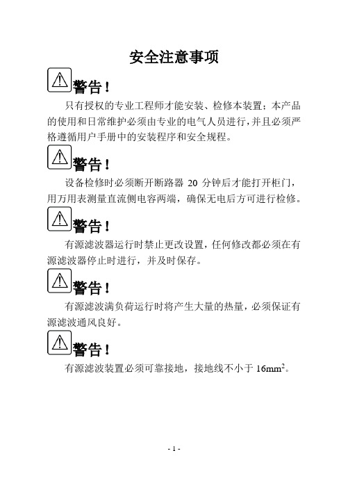
安全注意事项警告!只有授权的专业工程师才能安装、检修本装置;本产品的使用和日常维护必须由专业的电气人员进行,并且必须严格遵循用户手册中的安装程序和安全规程。
警告!设备检修时必须断开断路器20分钟后才能打开柜门,用万用表测量直流侧电容两端,确保无电后方可进行检修。
警告!有源滤波器运行时禁止更改设置,任何修改都必须在有源滤波器停止时进行,并及时保存。
警告!有源滤波满负荷运行时将产生大量的热量,必须保证有源滤波通风良好。
警告!有源滤波装置必须可靠接地,接地线不小于16mm2。
主要技术指标与使用要求目录1 结构简介 .............................................................................. - 4 -1.1主电路原理图 .............................................................. - 4 -1.2外形和主要结构尺寸 .................................................. - 5 -2 安装 (6)2.1机械安装 (6)2.2装置电气安装 (6)2.3 TA电气安装 (8)3 显示面板 (9)3.1主要功能及性能指标 (9)3.2界面说明 (10)4 运行操作 (17)4.1开机前检查 (17)4.2控制板及信号测试 (17)4.3试运行操作 (18)4.4运行操作 (18)5 维护 (20)6 故障处理 (21)6.1维修维护注意事项 (21)6.2故障处理一览表 (22)7 附件 (24)1 结构简介本装置由功率变流器、功率电感、直流侧电容、控制板、显示操作面板、高频滤波电路、电流电压检测电路、机柜等构成。
其结构如图1.1所示。
正视图左视图后视图图1.1有源滤波器结构图1.1主电路原理图主电路由输入保险FU1、FU2、FU3,断路器QF1,功率电感L1、L2、L3、L4、L5、L6,接触器KM1,IGBT及直流侧电容等组成,如图1.2所示。
APF操作手册
德殷能源科技(上海)有限公司 4.4 外形及安装图 .............................................................................................................. 19
4.4.1 壁挂式外形及安装图............................................................................................ 19 4.4.2 柜式外形及安装图................................................................................................ 20 5 功能与操作界面说明 ............................................................................................................... 20 5.1 人机界面概述................................................................................................................ 20 5.2 启动画面......................................................................................................................... 21 5.3 主界面 ............................................................................................................................ 22 5.4 监控界面........................................................................................................................ 23 5.5 系统参数........................................................................................................................ 23 5.5.1 电源侧参数 ........................................................................................................... 24 5.5.2 负载侧参数 ........................................................................................................... 24 5.5.3 APF 侧参数 ............................................................................................................ 25 5.5.4 联机状态............................................................................................................... 26 5.5.5 设备参数................................................................................................................ 27 5.6 曲线显示 ......................................................................................................................... 28 5.7 参数设置 ......................................................................................................................... 29 5.7.1 补偿设置................................................................................................................ 30 5.7.2 内部参数................................................................................................................ 31 5.7.3 报警故障............................................................................................................... 35 5.7.4 LCD 设置 ............................................................................................................... 36 5.7.5 联机设置............................................................................................................... 37 5.7.6 诊断维护设置 ....................................................................................................... 38 5.8 事件记录 ......................................................................................................................... 38 5.9 操作说明 ......................................................................................................................... 39 5.9.1 上电检查................................................................................................................ 39 5.9.2 启动步骤............................................................................................................... 39 5.10 设备维护........................................................................................................................ 40 6 常见问题的处理....................................................................................................................... 41 6.1 异常处理说明.................................................................................................................. 41 6.2 常见故障处理.................................................................................................................. 42
EXFO FIP-500和FIP-400B微观检查器的说明书
EMBOUTS POUR CÂBLE DE RACCORDEMENT / ADAPTATEURS MULTIFIBRES / APC ET UPC / MONOVOIE / MULTIVOIES / DUPLEXLa plus grande gamme d’adaptateurs et pointes de l’industries’adaptant à tous les connecteurs dans tous types de situation.Mécanisme innovant de connexion rapideRemplacez les pointes en un quart de tour - une innovation qui facilite grandement la vie. Pas de pièces détachées, pas une seconde perdue. Le changement d’embout peut se faire d’une seule main, si nécessaire. Il n’a jamais été aussi facilede passer d’un connecteur unitaire, à un duplex, à un multiple.FIP-500 SmarTipsInspection la plus rapide de l’industrie pour les connecteurs duplex, monovoies et multivoiesLe saviez-vous ?En appuyant votre SmarTip sur le FIP-500, les seuils de réussite/échec seront automatiquement ajustés au type de connecteur testé. Ce remarquable niveau d’automatisation permet d’éviter les erreurs de sélection des seuils et rendl’inspection des fibres plus facile que jamais!FIPOPTICAL HEADSMARTIP20214.5SmarTips pour les types de connecteurs les plus courants Chaque connecteur nécessite l’adaptateur approprié lorsqu’il s’agit d’inspecter des fibres. Pour faciliter au maximuml’utilisation ou la commande de l’adaptateur de pointe nécessaire, EXFO a élaboré ce guide de référence rapide. Il comprend la gamme complète des pointes disponibles, les connecteurs associés et les informations de commande correspondantes.OHSF OHSF-A60STIP-U2.5-ASTIP-SC-ASTIP-SC-A-LSTIP-U2.5-USTIP-SC-U-A60OHSF STIP-U1.25-APriseOHMFTête optiqueOHMF-A60Tête optique avec un angle de 60° pour les RAC-MPO-12-Type A+STIP-MPO-USTIP-MPO-UOHMFTête optiqueOHMF-A60 RAC-MPO-12-Type A+STIP-MPO-ASTIP-MPO-ARAC-MPO-16-Type A+STIP-MPO-USTIP-MPO-URAC-MPO-16-Type A+STIP-MPO-ASTIP-MPO-ARAC-MPO-12-Type A+STIP-MPO-A-KLSTIP-MPO-A-KLRAC-MPO-12-MTRAC-MPO-12-MTRAC-MPO-12-MTRAC-MPO-12-MTOHMF Tête optiqueOHMF-A60Tête optique avec un angle de 60° pour les STIP-LC-DF-U+Adaptateur de STIP-LC-DF-UOHMF Tête optiqueOHMF-A60Tête optique avec un angle de 60° pour lesSTIP-SN-DF-USTIP-SN-DF-USTIP-CS-DF-USTIP-CS-DF-USTIP-QODC-2-DF-U-FSTIP-QODC-2-DF-U-M Inspection duplex unique en une seule étapeFaites un gain de temps de 50 % sur l’inspection des connecteurs duplex, grâce à la conception innovanteSmarTip qui fournit un diagnostic succès/échec pour chaque fibre, ainsi qu’une vue en double fibre.PriseOHSF OHSF-A60STIP-U2.5-ASTIP-OTAP-AOHSFOHSF-A60 STIP-SFADP-400+FIPT-400-ODC-SSTIP-SFADP-400+FIPT-400-ODC-STIP-SFADP-400FIPT-400-ODC-4PIN-P-KOHMFTête optique OHMF-A60STIP-QODC-12-U-F STIP-QODC-12-U-MOHMFTête optique pourOHMF-A60 STIP-QODC-12-A-F STIP-QODC-12-A-MSTIP-QODC-2-DF-U-F STIP-QODC-2-DF-U-M STIP-OTIP-A-F STIP-OTIP-A-MSTIP-IP9-MPO-A STIP-MPO-AFIP-500 SmarTip informations pour la commandeEXFO offre plusieurs pointes de câble de raccordement et adaptateurs de cloison pour les connecteurs monovoies et multivoies. Ces embouts et adaptateurs sont conçus pour s’adapter à la vaste gamme rencontrés sur le terrain. Les pointes et adaptateurs suivants sont compatibles avec les séries FIP-500 et FIP-400B d’EXFO et peuvent être commandés séparément ou en kits. Veuillez consulter les tableaux ci-dessous pour obtenir des renseignements complets sur la façon de commander.Câbles de raccordement universel STIPSTIP-U1.25-UCâble de raccordementuniversel 1,25 mm/UPCConnecteurs de cloison STIPsConnecteur de cloison STIPsCompatibilité du FIP-500 avec les emboutsFIP-500TÊTE OPTIQUEADAPTATEURFIPT-400Les types de connecteurs et d’embouts les plus courants pour la série FIP-400B ou le FIP-500 équipé d’un OHSF sont énumérés ci-dessous.Série d’embouts pour FIP-400BNos microscopes d’inspection de fibres FIP-400B utilisent un jeu d’embouts différent. Cependant, ces pointes peuvent également être utilisées avec le FIP-500 en ajoutant simplement la tête optique pour fibre monovoie.FIPT-400-U25MAFIPT-400-U25MFIPT-400-FC-SCFIPT-400-FC-APCFIPT-400-STFIPT-400- FIPT-400-E2000FIPT-400-U12MAFIPT-400-LX5-APCFIPT-400-U12MFIPT-400-LX.5FIPT-400-MU FIPT-400-LC-APCFIPT-400-LC-SQFIPT-400-LC-D-APCFIPT-400-LC-DFIP EMBOUTS,FIP EMBOUT BUSE ADAPTATEURNon nécessaire lorsque la buse dédiée au connecteurmâle est disponible.Voir page suivante* Nécessite la version FIP-400B MF-Ready.FIP-400B Tip information de commandeFIPT-400-U25MA-R®FIPT -400-FC-SC-A6FIPT -400-MTRJ*FIPT -400-MUFIPT -400-SC-APC-L* Analyse réussite/échec non prise en charge.Pointes, buses et adaptateurs multifibres automatisés* Têtes FIPT-400-MF-MPODescription Embout automatisé pourconnecteurs MPO/UPC(rangée de 12 fibres),utilisable d’une seulepatible avec les* Nécessite la version FIP-400B MF-Ready.* L’analyse réussite/échec n’est pas prise en charge par ConnectorMax Mobile pour les appareils intelligents.FIPT -400-QODC-2P-K20220444V2© 2023 EXFO Inc. Tous droits réservés.Imprimé au Canada 23/041Écrou de retenue argentéPour plus d’informations sur l’inspection automatisée des fibres, consultez le site /KeepTheFocus1234。
FVN P-400 无直接燃烧空间暖气器操作指南说明书
OPERATING INSTRUCTIONS MANUAL(Please retain for future reference)ForFVN/P-400 INDIRECT FIRED SPACE HEATERSCERTIFIED FOR USE IN CANADA AND U.S.A.As per Standard ANSI Z83.7/CSA 21.4 2000 Gas Fired Construction Heaters / Unattended Type.Issue date October 1, 2008FLAGRO INDUSTRIES LIMITEDST. CATHARINES, ONTARIOCANADAGENERAL HAZARD WARNING:FAILURE TO COMPLY WITH THE PRECAUTIONS AND INSTRUCTIONS PROVIDED WITH THIS HEATER, CAN RESULT IN DEATH, SERIOUS BODILY INJURY AND PROPERTY LOSS OR DAMAGE FROM HAZARDS OF FIRE, EXPLOSION, BURN, ASPHYXIATION, CARBON MONOXIDE POISONING, AND/OR ELECTRICAL SHOCK.ONLY PERSONS WHO CAN UNDERSTAND AND FOLLOW THE INSTRUCTIONS SHOULD USE OR SERVICE THIS HEATER.IF YOU NEED ASSISTANCE OR HEATER INFORMATION SUCH AS AN INSTRUCTIONS MANUAL, LABELS, ETC. CONTACT THE MANUFACTURER.WARNING:FIRE, BURN, INHALATION, AND EXPLOSION HAZARD. KEEP SOLID COMBUSTIBLES, SUCH AS BUILDING MATERIALS, PAPER OR CARDBOARD, A SAFE DISTANCE AWAY FROM THE HEATER AS RECOMMENDED BY THE INSTRUCTIONS. NEVER USE THE HEATER IN SPACES WHICH DO OR MAY CONTAIN VOLATILE OR AIRBORNE COMBUSTIBLES, OR PRODUCTS SUCH AS GASOLINE, SOLVENTS, PAINT THINNER, DUST PARTICLES OR UNKNOWN CHEMICALS.WARNING:NOT FOR HOME OR RECREATIONAL VEHICLE USE.WARNING:INTENDED USE IS PRIMARILY THE TEMPORARY HEATING OF BUILDINGS UNDER CONSTRUCTION, ALTERATION, REPAIR OR EMERGENCIES ONLY.ALWAYS PROVIDE ADEQUATE VENTILATION. 1 SQ. IN. OF FRESH AIR MUST BE SUPPLIED FOR EVERY 1000 BTUH OF HEAT.THIS HEATER SHALL BE INSTALLED SUCH THAT IT IS NOT DIRECTLY EXPOSED TO WATER SPRAY, AND/OR DRIPPING WATER.This heater is designed and approved for use as aconstruction heater under Standard ANSI Z83.7/CGA 2.14. 2000.We cannot anticipate every use which may be madeof our heaters. CHECK WITH YOU LOCAL FIRESAFETY AUTHORITY IF YOU HAVE QUESTIONSABOUT APPLICATIONS.Other standards govern the use of fuel gases and heatproducing products in specific applications. Your localauthority can advise you about these.SPECIFICATIONSModel …………………………………………………….…. FVP-400 PropaneFVN-400 Natural Gas Input …………………………………………………….…... 390,000 btuhFuel …………………………………………………………. FVP-400 PropaneFVN-400 Natural Gas Manifold Pressure …………………………………………. 3.2” W.C. Propane2.0” W.C. NG Maximum Inlet Pressure ………………………………… 13.0” W.C. Propane10.0” W.C. NG Ignition ……………………………………………………… Direct Spark Ignition …….……………………………………………...… Thermostat Control Air Circulation ………………………………………………. 2500 cfmFuel Consumption ………………………………………..... 18.5 lbs/hr PropaneNG 380cfh Approved …………………………………………………..... cETLus listedINSTALLATION:The installation of this heater for use with natural gas shall conform with local codes or, in the absence of codes, with the National Fuel Gas Code ANSI Z233.1/NFPA 54 and the Natural Gas and Propane Installation Code, CSA B149.1-00. This heater must be installed by a qualified gas technician, following local codes published by the authority having jurisdiction. All installations performed in the state of Massachusetts must be completed by a qualified plumber and gas fitter of the State of Massachusetts.The installation of this heater for use with propane tank or cylinder shall conform with Local codes or, in the absence of local codes, with the Standard for the Storage and Handling of Liquefied Petroleum Gases, ANSI Z233/NFPA 54 and the Natural Gas and Propane Installation Code, CSA B149.This heater must be located at least 10ft (3m) from any propane gas cylinder. This heater shall not be directed toward any propane gas container within 20ft (6m).CONNECTING THE CYLINDER (LP Models only):If cylinders are used to supply the heater, no cylinders smaller than 100lb capacity shall be used. These cylinders must supply a vapor withdrawal only.1. All cylinder connections must be made using a wrench to tighten the POLfitting.2. Be sure that the cylinder valve is in the closed position when connection ordisconnecting the cylinder.3. A soap and water solution must be applied to all connections in order toleak check the system.The gas must be turned off at the propane supply cylinder(s) when the heater is not in use. When the heater is to be stored indoors, the connection between the propane supply cylinder(s) and the heater must be disconnected and the cylinders removed from the heater and stored in accordance with Standard for the Storage and Handling or Liquefied Petroleum Gases, ANSI/NFPA 58 and CSA B149.1, Natural Gas and Propane Installation Code.PIPING:This heater must be installed by a qualified gas technician following local codes published by the authority having jurisdiction. Sizing ofsupply piping must be determined using the length of pipe run aswell as total btuh rating of the appliance(s). Appropriate pipingtables must be used to determine size of supply piping dependanton the length of run from source.PRESSURES:MAXIMUM INLET PRESSURES: LP: 13.0 IN. WC.IN.WC.10.0NG:MINIMUM INLET PRESSURES: LP: 8.0 IN. WC.IN.WC.4.0NG:This heater must be supplied by pressures indicated on theapproval label. Over pressure may cause controls to fail.DONOT supply this unit with more than ½ psig (14.0 in.W.C.)Note: A second stage regulator must be installed if thesupply pressure exceeds ½ psig.FUEL:This heater will operate on propane OR natural gas – NOTBOTH. The manifold pressures are listed on the approvallabel. To determine which fuel to use see rating plate. DONOT attempt to use the heater without consulting the ratingplate.Note: The proper main burner orifice must be installed andrating plate must reflect the fuel the heater burning. DONOT operate the heater with out consulting the rating plate.Heater conversion must be done by a qualified technicianand rating plate must reflect any change.HOSES:All hoses used to connect this heater of fuel supply must beType 1 approved propane / natural gas hose assemblies.ELECTRICAL:WARNINGInstructionsGroundingElectricalThis appliance is equipped with a three-prong (grounding)plug for your protection against shock hazard and should beplugged directly into a properly grounded three-prongreceptacle.115v supply must be available. Please note that the heaterrequires 15 amps for proper operation. Ensure appropriategauge extension cord is used.• 12/3 AWG at 50 Feet• 10/3 AWG at 100 FeetCLEARANCE TO COMBUSTIBLES:PIPE TOP FRONT SIDES REAR FLUE3 ft 10 ft 3 ft 3 ft 3 ftDUCTING: Canvas heater duct with a minimum temperature handling of300 deg F. including wire reinforcement to preventcollapsing. Heater is designed for use with 2 x 12” diameterducts equipped with pin lock couplings (FV-D12).Install ducting to outlet on the heater using pin-locksprovided on collar of ducting. Ducting should be inspectedperiodically for tearing and/or wear marks. Ducting should bestored in a dry area when not in useFLUE PIPE: Flue pipe connection must terminate with a vertical run atleast 2ft long.The vent outlet on the heater is 6” diameter. Certified ventingmust be used at all times. Vent cap should be installed insituations where downdrafts occur. All venting mustcorrespond with the CSA B149 standard or in its absence,local codes.FV SERIES CONSTRUCTION HEATER – VENTING REQUIREMENTS1. VERTICAL FLUE TERMINATIONSFLUE OUTLET OF HEATER2. HORIZONTAL FLUE TERMINATIONSFLUE OUTLET OF HEATERA - VENT TERMINATION MUST BE A MINIMUM OF 2FT HIGHER THAN ANY POINTWITHIN 10FT.B - MAXIMUM HORIZONTAL RUN IS 30FT.NOTE: 90deg ELBOW = 10ft HORIZONTAL VENT ALLOWANCE45deg ELBOW = 5ft HORIZONTAL VENT ALLOWANCEC - VENT TERMINATION IN HORIZONTAL POSITION MUST BE MINIMUM 4ft FROM ANYCOMBUSTABLE SURFACED - EXTERIOR VERTICAL VENT TERMINATION MUST BE A MINIMUM OF 2ft.NOTE: ALL VENT TERMINATIONS MUST HAVE A RAIN CAP INSTALLED AS PER LOCAL CODE REQUIREMENTS.MAINTENANCE:1. Every construction heater should be inspected before each use, and atleast annually by a qualified service person. Incorrect maintenance my result in improper operation of the heater and serious injury could occur.2. Service and maintenance should only be done by a qualified service person.3. The hose assemblies shall be visually inspected prior to each use of theheater. If it is evident there is excessive abrasion or wear, or the hose is cut, it must be replaced prior to the heater being put into operation. The replacement hose assembly shall be that specified by the manufacturer.4. The appliance must be kept clear and free from combustible materials,gasoline and other flammable vapors and liquids.5. The flow of combustion and ventilation air must not be obstructed. Be sure tocheck the fan assembly and ensure that the motor and blade are operating properly.6. Compressed air should be used to keep components free of dust and dirtbuild up. Note: Do not use the compressed air inside any piping or regulator components.7. Fan Limit Switch (Part# FV-407A) should be replaced if the fan motor doesnot shut off after the heat exchanger has cooled down.8. High Limit Switches (Part# FV-406 and FV-437) should be checked eachseason. These limit switches will ensure the burner shuts down if the temperature exceeds 150°F degrees at rear of unit and 290°F at the outlet. 9. Heat Exchanger should be cleaned if smokey conditions continue even afterthe air adjustments on the burner are made.START UP INSTRUCTIONS:1. Be sure the switch is in the “OFF” position.2. Ensure electrical cord is grounded and heater is on a level surface.3. Plug in supply cord to 115v, 15amp outlet.4. Move switch to “MANUAL” position for manual control.5. Move switch to “THERMOSTAT” position for thermostatic control. Please Note:1. If using Thermostat on unit, unit must be started in Thermostat position.2. When changing between manual and thermostat operation, the heatermust be left in the “OFF” position for 30 seconds to prevent the burner from locking out.3. When using a generator for electrical supply, make sure the generator isproperly grounded and generator is at a 60Hz frequency.4. In the event that a generator is being used and the generator runs out offuel, make sure the heater switch is in the “OFF” position before restarting generator, failure to do so may damage heater.TO SHUT DOWN:1. Close main gas supply valve while heater is operating.2. Move switch to “OFF” position.3. Disconnect heater from gas supply.NOTE: Fan will continue to operate after the burner shuts down. Once the unit cools down, the fan will stop.IF HEATER FAILS TO START:1. Press manual reset button at rear of burner.2. Check gas pressure supply. Supply and manifold pressure mustfollow those on rating plate.3. Ensure proper power supply and extension cord is being used.4. If heater fails to ignite after 3 attempts, call your supplier for service.SAFE OPERATION PRECAUTIONS:1. For use with propane or natural gas only. See approval label.2. Use switch to shut down the heater. Do not try to shut down the heaterby unplugging the electrical cord.3. Do not plug anything other that the thermostat into the “Thermostat”plug.4. Follow electrical requirements shown on rating plate and/or Electricalrequirements section of this manual.5. Before removing any guards or performing any maintenance, be surethat the main power supply is disconnected.COMBUSTION AIR ADJUSTMENTS:NOTE:Proper combustion air adjustment must be achieved using a certified combustion analyzer to ensure complete combustion.The air adjustment should be made to achieve 10% CO2 on naturalgas and 12% CO2 on propane.SETTING THE AIR ADJUSTMENT PLATEA) Regulation of the combustion air flow is made by adjustment of the manual AIR ADJUSTMENT PLATE (1) after loosening the FIXING SCREWS (2 and 3). The initial setting of the air adjustment plate should be made according toColumn 5 in the Burner Set-up Chart.B) The proper number on the manual AIR ADJUSTMENT PLATE (1) should line up with the SETTING INDICATOR (4) on the fan housing cover. Once set, the air ad-justment plate should be secured in place by tightening SCREWS 2 and 3.C) The final position of the air adjustment plate will vary on each installation. Use in-struments to establish the proper settings for maximum CO 2.NOTE: Variations in flue gas, CO 2 and temperature readings may beexperienced when the burner cover is put in place. Therefore, the burner cover must be in place when making the final combustion instrument readings, to ensure proper test results.BURNER SET-UP CHART12345FIRING RATE (BTUH) ORIFICE-LP ORIFICE-NG HEAD SETTINGAIR DAMPER SETTING390,000PART # FVP-425PART # FVN-42654.8TEMPERATURE FEELER GAUGE ADJUSTMENT(ATTACHED TO FAN SWITCH)The temperature feeler gauge is required to be always touching the heater exchanger.The temperature feeler gauge controls the air flow over the fan switch, which eliminates any unnecessary fan cycling. The temperature feeler gauge can be adjusted for different outside temperatures, by rotating the location of the temperature feeler gauge holes. This will provide maximum performance of the unit in different applications.If supply air is warm (-5° C, indoor application):Turn the temperature feeler gauge so that the holes are parallel with the heat exchanger. This will help the fan switch to remain cool and not overheat. See following:If supply air is cold (under -5° C):Turn the temperature feeler gauge so that the holes are closed off as the air goes over the heat exchanger. This will reduce fan cycling and the unit from shutting down.See following:In extreme cold conditions, cover the holes on the temperature feeler gauge using foil tape. Ensure that the temperature feeler gauge is readjusted for warmer weather conditions. Failure to do so may result in burning out fan switches – not covered under warranty.PRINCIPAL BURNER COMPONENTS1. Air Damper (Optional Delete)2. Air Gate Lock-screws3. Wiring Terminal Block4. Air Pressure Switch5. Motor6. Lockout Lamps and ResetButton7. Cover Screw8. Rubber Grommet9. CapacitorBURNER DIMENSIONSModel 400 A B C F G *G1 H inches 10 5/16 12 1 3/8 13 11/16 3 3/4 10 4 1/8 mm 2262 305 35 347 95 255 61 *G1 is for LBT version - Gasket thickness is 4 millimetersELECTRODE AND FLAME PROBE ADJUSTMENTSIMPORTANT: Do not turn the ignition electrode. Leave it as shown in the drawing. If the ignition electrode is put near the ionization probe, the amplifier of the control box may be damaged.TYPICAL GAS TRAIN LAYOUTFIELD SUPPLIED RIELLO SUPPLIEDGAS TRAIN LEGENDn GAS SUPPLY & FLOW DIRECTIONOF GASrGAS APPLIANCE PRESSURE REGULATORo AS SUPPLY MAIN SHUTOFF MANUAL VALVE (FIELD SUPPLIEDsSAFETY SHUTOFF GAS VALVE (VS) 24V OR 120V SUPPLIED) OPERATEDp GAS SUPPLY PRESSURE TESTPOINT (FIELD SUPPLIED)tMAIN GAS VALVE (V1) 24V OR 120V OPERATED SINGLE STAGEq GAS TRAIN PIPE DIAMETER SIZE(S): BURNER G120 1/2" NPT (REDUCED AT COMBUSTION HEAD TO 3/8") BURNER(S) G200 & G400 3/4" NPTuGAS BURNER MANIFOLD TEST POINTGAS SUPPLY PRESSURE RANGES:NATURAL GAS PRESSURE: MIN. = 4.0″WC MAX. 10.5″ WCL.P. PROPANE GAS PRESSURE MIN. = 8.0″ WC MAX. 13.0″ WCFIELD WIRING DIAGRAMFACTORY WIRING DIAGRAMNOTE:1. This burner is approved for use without the motorized air damper. In theseinstances optional wiring is used2. The SAFETY SWITCH on the 525 SE CONTROL BOX is equipped with acontact allowing remote sensing of burner lockout. The electrical connection is located on the CONTROL BOX terminal 4 as indicated. Should burner lockout occur, the 525 SE CONTROL BOX will supply a power source of 120 Vac to the connection terminal. The maximum allowable current draw on this terminal is 1 A.PARTS PRICE LIST 2008/2009FVN-400 & FVP-400 INDIRECT FIRED HEATERSPART NUMBER DESCRIPTION LIST PRICEFV-401 Primary Fan Motor 488.40FV-402 16” Fan Blade 169.80FV-403 16” Wheel 195.00FV-404 18” Power Cord 36.00FV-405 SS Heat Exchanger 2140.00FV-406 High Limit Switch (Outlet) 37.80FV-407A Fan Limit Switch (Adjustable) 39.80FV-408 Fan Motor Canopy 90.00FV-409 Toggle Switch (on control box) 39.50FV-410 Green Light (on control box) 18.40FV-411 Red Light (on control box) 18.40Contactor 52.50 FV-412 RelayFV-414 Thermostat Plug (on control box) 11.25FV-414A Thermostat Plug (on control box) 2008> 11.25FVNP-424 Riello Burner (FVN-400 & FVP-400) 3287.00FVP-425 LP Burner Orifice for FVP-400 56.20FVN-426 NG Burner Orifice for FVN-400 56.20AssemblyHose 30.20S6012-12 Valve349-12E Steel Elbow (3/4”MP X 3/4”F.JIC) 14.8340-100-12 Sch 40 Elbow (3/4”) 1.47FVNP-427 Maxitrol Regulator (RV52) 115.60FVNP-428 Mag Type 200 Solenoid Valve 380.25FVNP-429 Asco Solenoid Valve 235.40FVNP-430 Valve Assembly Mounting Brackets (2) 18.00FV-431 Burner Gasket 32.50Gauge 13.60 FV-433 FeelerGauge-Solid 13.60 FV-433B FeelerFV-434 Front Face Plate (2 x 12”) 182.00FV-434A Front Face Plate (1 x 16”) 182.00FV-437 High Limit (Rear) 37.80Harness 129.20 FV-438 LiftingFV-439 Circuit Breaker 15 Amps 16.80FV-446 Sight Glass c/w Fiber gasket 11.10FV-447 Sightwasher 11.10GlassFVNP-300162 Ignition Module (LP/NG) 701.90FVNP-3005447 Gas Pressure Test Point Adapter 16.95FVNP-3006688 Chassis Mounting Collar 61.00FVNP-3006699 Distributor Head & Mixing Plate 190.50Assembly 156.48 FVNP-3007276 ElectrodeAssembly 88.92 FVNP-3007277 FlameRodLead 10.10 FVNP-3007310 IonizationFVNP-3007448 Ground Lead & Connector For G400 Burner 11.00 FVNP-3020321 Air pressure Switch for G400 Burner 352.00ACCESSORIESFV-D12 12” X 12ft Canvas Ducting 212.00 FV-D16 16” X 16ft Canvas Ducting 530.00 FV-TH Thermostat c/w 25FT Cord 236.00 FVN-427 LP to NG Conversion Kit for FVP-400 56.20 FVP-428 NG to LP Conversion Kit for FVN-400 56.20FV-VK 6” x 3FT C-Vent c/w Rain Cap 74.20。
Mobile Fuel Filtration All 400 Series 手动燃油滤芯水分离器说明
All 400 Series spin-on fuel filter/water separators feature a hand (palm) operated fuel priming4120R 490R460R445Rcontamination, and are available in 2, 10 and30 micron. Filtration needs should be basedon application, fuel quality, operating climates,and maintenance schedules. Also included are445R460R490R4120R60 GPH (227 LPH)90 GPH (341 LPH)120 GPH (454 LPH)3/4”-16 SAE(SAE J1926)4222.0 in. (5.1 cm)1”-1415.0 in. (38.1 cm)4.5 in. (11.4 cm)73Hand actuatedprimer pump Installation Instructions Refer to Mounting Instructions and InstallationDiagram and install as follows:Make sure engine is off and cool to touch.45R, 460R and 490R: Apply thread sealantto NPT fittings (do not use thread tapes asparticles may break off and contribute toValve400 SeriesElement replacement frequency is determined by contamination level in fuels. Fuel flow to engine becomes restricted as element gradually plugs with contaminants, resulting in noticeable power loss and/or hard starting. As a guideline, change element every 500 hours, 10,000 miles, every other oil change, annually, or at first indication of power loss, whichever occurs first. Always carry extra replacement elements as one tankful of excessively dirty fuel can quickly plug a filter.1. Make sure engine is off and cool to touch.2. C lose all fuel valves, if applicable, to makesure excess fuel does dot spill duringservicing.3. D isconnect water probe and heaterconnectors, if equipped.4. Open vent plug on mounting head.5. Drain unit of fuel.6. R emove bowl and element. Dispose elementproperly. Bowl is reusable.7. L ubricate new element seals with motor oil orclean fuel and install only with new element.8. R e-install bowl and tighten by hand only - donot use tools.9. C onnect water probe and heater connectors,if equipped.10. Open all fuel valves, if applicable.11. O perate hand primer pump until fuel purgesfrom vent.12. C lose vent plug and start engine. Correct asnecessary with engine off.Draining the Collection BowlWater is heavier than fuel and will settle to bottom of bowl and appear different in color if collected in a clear jar. In high humidity environments, check bowl frequently (daily if a poor fuel source is suspected). 400 Series bowls are equipped witha water sensor port that will accept a water probe (sold separately) and will alert operator of a high water condition in the filter.Do NOT use water probe electronics in gasoline applications - an explosion could occur.1. Make sure engine is off and cool to touch.2. Open vent plug.3. D rain water from filter by opening self-ventingdrain. Close as soon as all water hasevacuated.If drain is open too long, the entire filter may drain completely of water and fuel4. Follow priming instructions.Priming Instructions1. P rime filter by operating hand primer pumpuntil fuel spills out of vent port.2. Close vent plug snugly.3. Verify all other connections are tight.4. S tart engine and check for leaks. Correct asnecessary with engine off.If a 400 Series filter fails to hold prime, first check vent plug, drain valve, fittings, head, element and bowl are properly tightened. Next, check fuel line connections and verify that they are free of pinches or unnecessary bends and check to see if fuel tank strainer (or pick-up tube) is clogged. If problems persist and element is new, call Racor Technical Support at the number listed below.Service InstructionsTroubleShooting76Technical Support:800.344.3286 ext. 7555racortech@108 10。
ABB ACS400 变频器 说明书
警告 ! 电机停止后,在主回路端子上 (U1, V1, W1 和 U2, V2, W2 及 U 存在。
c+,
Uc-)
依然有危险电压
警告 ! ACS 400 断电后,在继电器端子上 ( RO1A, RO1B, RO1C, RO2A, RO2B, RO2C) 依 然可能有外部危险电压。 警告 ! 不要试图修理损坏的单元,请与供应商联系。 警告 ! 当输入电源断电之后再次恢复时,如果外部运行指令为 ON,ACS 400 将自动起动。 警告 ! 当两个以上的 ACS100/140/400 的控制端子并联使用时,用于控制连接的辅助电源应 来自同一个单元或外部电源。 警告 ! 散热器的温度可能很高 ( 参看 S,表 11)。 注意 ! 欲获取详细的技术信息,请与供应商联系。
ACS 400
用户手册
vii
编程 . . . . . . . . . . . . . . . . . . . . . . . . . . . . . . . . . . . . . . . . . . . 29
控制方式 . . . . . . . . . . . . . . . . . . . . . . . . . . . . . . . . . . . . . . . . . . . . 29 输出显示 . . . . . . . . . . . . . . . . . . . . . . . . . . . . . . . . . . . . . . . . . . . . 30 菜单结构 . . . . . . . . . . . . . . . . . . . . . . . . . . . . . . . . . . . . . . . . . . . . 30 设定参数值 . . . . . . . . . . . . . . . . . . . . . . . . . . . . . . . . . . . . . . . . . . 31 菜单功能 . . . . . . . . . . . . . . . . . . . . . . . . . . . . . . . . . . . . . . . . . . . . 32 LED 指示 . . . . . . . . . . . . . . . . . . . . . . . . . . . . . . . . . . . . . . . . . . . 33 故障诊断显示 . . . . . . . . . . . . . . . . . . . . . . . . . . . . . . . . . . . . . . . . 34 控制盘复位故障 . . . . . . . . . . . . . . . . . . . . . . . . . . . . . . . . . . . . . . 34 对比度调整 . . . . . . . . . . . . . . . . . . . . . . . . . . . . . . . . . . . . . . . . . . 34 ACS100-PAN 控制盘 . . . . . . . . . . . . . . . . . . . . . . . . . . . . . . . . . . . . 35 控制方式 . . . . . . . . . . . . . . . . . . . . . . . . . . . . . . . . . . . . . . . . . . . . 35 输出显示 . . . . . . . . . . . . . . . . . . . . . . . . . . . . . . . . . . . . . . . . . . . . 36 菜单结构 . . . . . . . . . . . . . . . . . . . . . . . . . . . . . . . . . . . . . . . . . . . . 36 设定参数值 . . . . . . . . . . . . . . . . . . . . . . . . . . . . . . . . . . . . . . . . . . 36 菜单功能 . . . . . . . . . . . . . . . . . . . . . . . . . . . . . . . . . . . . . . . . . . . . 37 故障诊断显示 . . . . . . . . . . . . . . . . . . . . . . . . . . . . . . . . . . . . . . . . 38 控制盘复位故障 . . . . . . . . . . . . . . . . . . . . . . . . . . . . . . . . . . . . . . 38 ACS 400 基本参数 . . . . . . . . . . . . . . . . . . . . . . . . . . . . . . . . . . . . . . 39 应用宏 . . . . . . . . . . . . . . . . . . . . . . . . . . . . . . . . . . . . . . . . . . . . . . . 43 应用宏 Factory (0) . . . . . . . . . . . . . . . . . . . . . . . . . . . . . . . . . . . . 44 应用宏 Factory (1) . . . . . . . . . . . . . . . . . . . . . . . . . . . . . . . . . . . . 45 应用宏 - ABB 标准型 . . . . . . . . . . . . . . . . . . . . . . . . . . . . . . . . . . 46 应用宏 - 三线型 (3-wire) . . . . . . . . . . . . . . . . . . . . . . . . . . . . . . . . 47 应用宏 - 交变型 (Alternate) . . . . . . . . . . . . . . . . . . . . . . . . . . . . . . 48 应用宏 - 电动电位器型 (Motor Potentiometer) . . . . . . . . . . . . . . . 49 应用宏 - 手动 / 自动型 . . . . . . . . . . . . . . . . . . . . . . . . . . . . . . . . . . 50 应用宏 - PID 控制 . . . . . . . . . . . . . . . . . . . . . . . . . . . . . . . . . . . . . 51 应用宏 - 预磁通 (Premagnetise) . . . . . . . . . . . . . . . . . . . . . . . . . . 52 应用宏 - PFC 控制 . . . . . . . . . . . . . . . . . . . . . . . . . . . . . . . . . . . . 53
- 1、下载文档前请自行甄别文档内容的完整性,平台不提供额外的编辑、内容补充、找答案等附加服务。
- 2、"仅部分预览"的文档,不可在线预览部分如存在完整性等问题,可反馈申请退款(可完整预览的文档不适用该条件!)。
- 3、如文档侵犯您的权益,请联系客服反馈,我们会尽快为您处理(人工客服工作时间:9:00-18:30)。
AFP-300/AFP-400 消防控制柜操作手册目录表1.简介概述操作特点部件2.使用控制盘概述系统状态指示灯LED控制健3.操作方式正常操作故障操作火灾报警监视信号非报警点操作故障监控点操作通知广播设备电路(NAC)操作事件控制操作释放功能智能检测器功能预报警操作(AWACS)时间功能概述操作编码功能预警/报警顺序(PAS)操作专用系统计时器水流电路操作禁止/允许操作STYLE6操作4.读取状态概述如何读取状态读状态选择读取点和区域状态读取检测器,模板和输出状态读取历史状态查看报警历史查看或打印隐藏历史预警信号延时释放区时间控制区假日区NAC编码区预报警区系统参数信号器显示选择信号器显示选择实例5.声音报警系统概述操作特点本节内容开始准备AMG-1/AMG-E音频消息发生器AMG-1/AMG-E概述AMG-1/AMG-E操作特点操作AMG-1选择AMG-1组功能选择AMG-E音调和消息ATG-2音频音调发生器ATG-2概述如何操作ATG-2选择ATG-2音调选择主通道(撤空)音调选择从通道(警告)音调选择操作方式消防电话(FFT-7/FFT-7S)概述FFT-7操作部件操作FFT-7音频放大器概述音频放大器特点AA-30音频放大器AA-100/AA-120音频放大器调整音频增益电平(AA-30,AA-100/AA-120音频放大器)选择AA-100/AA-120后备音调AMG声音消息选择概述安装1.简介概貌AFP-300/AFP-400是模块化,智能消防控制盘,具有广泛且强大的功能。
CPU模板、电源模板和柜体构成了一种功能强大的防火控制系统,可用于多种场合。
可选模板安装在机架上,提供了附加的输出电路。
操作特点●按点与标签进行报警检验选择。
●正向报警顺序(PAS),按NFPA 72 1993 预信号。
●消音禁止计时器,自动消音计时器。
●行进计时/临时编码用于通知广播系统(NAC)。
●若使用UZC-256可选功能,可对NAC进行区域编码。
●通过MMX监视模板,实现报警消音/系统复位/报警激励功能。
●自动时间和星期控制功能,有假日选择。
●用户定义密码和钥匙保护式非挥发存储器。
●AWACS(先进警示可寻址燃烧检测)带有9个现场可调预警级别,具有可编程事件控制(CBE)。
●根据动作的预报警级别,操作自动烟感或温感探测器声响器;具有撤空报警级别。
●安全报警点选择,带有不同的音响信号编码。
●集中声音调度和声响报警信号选择。
●可编程事件控制,控制由各自报警或监视可寻址设备的输出。
部件图1中给出了与控制盘操作有关的部件2.操作控制盘概述表1 列出控制与指示灯以及使用信息:表1 控制与指示灯系统状态指示灯控制盘有8个LED指示灯,其标签如下:图1系统状态指示灯表2中系系统状态指示灯LED的说明表2系统状态指示灯的说明控制健控制盘上有5个控制健:确认/步进,报警消音,报警激励,系统复位,和灯测试键。
确认/步进健:出现新报警或故障信号时,用此键确认。
按此健控制盘完成如下功能:●消除控制盘音响;●使闪亮灯变亮;●发送确认消息到历史文件,可选打印机,可选显示屏;●发出消音信号使LCD-80和ACS 上的音响禁止;可以使用该键显示多个报警或故障。
如果一个以上的报警或故障存在,控制盘显示下一个报警或故障3秒(或到按<确认键>),而后显示下一个报警或故障。
报警消音健:按该健使控制盘音响和通知广播电路消音,按此健控制盘完成如下任务:●关闭控制盘音响;●关闭音响输出电路;●报警消音灯亮;●发送报警消音消息到历史文件,可选打印机,可选显示屏LCD-80;报警激励健:按该健测试通知广播电路。
按此健持续2秒,控制盘完成如下任务:●激励所有可消音的NAC;●报警消音灯灭;●发送一个手动清空消息到历史文件,可选打印机,和可选LCD-80;系统复位健:用该健复位系统控制盘。
按此健控制盘完成如下任务:●关闭所有报警激励的CMX模板和NAC电路;●将4线制探头的可复位电源切断;●发送一条全系统正常的消息到历史文件,可选打印机,可选显示屏LCD-80;系统复位后,所存在的报警或故障重新激励NAC,控制输出和盘的音响和视频指示灯。
灯测试建健:使用此健测试控制盘LEDS灯和音响器。
按此健控制盘完成如下任务:●全部盘上指示灯亮;●控制盘音响器发声;●LCD码管的各段灯亮;3.操作方式正常操作当系统中无报警或无故障时,系统为正常方式操作,控制盘显示消息如下:图3 所有系统正常消息正常方式时,控制盘周期性地执行如下操作:●查询所有信号总线电路(SLC)设备,4个NAC检查有效的应答,报警,故障,电路完整性,等。
●十秒钟检查一次供电电源和电池。
●向LCD-80发送监控查询,并检查其相应的响应。
●刷新LCD,和可选LCD-80显示屏,更新时间。
●扫描系统复位或输入键盘。
●执行探头自动测试操作。
●测试系统存储器。
故障操作控制盘检测到电器或机械故障时,系统进入故障方式。
无报警时,故障方式的控制盘工作如下:●产生脉冲声音音调脉冲;●系统故障灯闪亮;●故障继电器激励(MPS-400,TB3);●发送一个消息到LCD显示屏,可选LCD-80,可选打印机,和历史文件。
图4给出了一个典型的故障消息:事件类型(故障)设备类型该设备位置的说明软件区指定故障类型时间日期图4故障消息1.按确认键,消除盘的声音,并且系统故障灯由闪亮变为常亮。
与故障,报警,和监控的信号的多少无关。
2.当故障或报警存在时,按确认键,控制盘发送一条确认消息到历史文件和可选打印机。
注:CMX模板报告开路和短路电路的消息。
如果故障消除(按确认键前),控制盘发送一条故障消除消息到打印机。
图5给出消息故障例子:图5消息故障例子如果所有故障消除,无监控或火灾条件存在,控制盘进行如下工作:●返回正常操作方式;●发送“系统正常”消息到LCD显示屏,历史文件,可选LCD-80, 可选打印机;●即使故障没有确认,自动重新存储故障。
当只有故障时,按消音键,其结果与按确认键相同。
除非系统中有报警,否则报警消音灯不亮。
若系统中有多个故障,LCD和可选LCD-80显示器自动步进,每3秒钟显示一个故障。
其顺序如下:1.报警,按地址顺序显示。
2.监控,按地址顺序显示。
3.故障,按地址顺序显示。
按确认键,显示器停在当前显示故障上1分钟。
再按确认键,继续。
火灾报警当控制盘检测到火灾报警时,系统进入火灾报警方式。
在此方式下,控制盘的工作如下:●发出恒定的音响;●激励系统报警继电器(MPS-400,TB),系统报警灯闪亮;●LCD显示屏上,显示报警状态标志;●锁定报警,使其在产生报警设备返回正常条件前和操作员复位控制盘以前,不能消除报警;●启动事件控制动作;●开始记时(消音抑制,自动消音);●激励总报警区(Z00)报警状态标志图6 火警显示监视信号监视信号使控制盘进行如下操作:●产生鸟鸣声音调;●激励监控继电器(MPS-400 TB5),监控灯闪亮;●控制盘状态标志位显示“Active”;●关闭所有可消音的音报警的控制盘音响器。
状态标志Active图7 典型监控信号显示非报警点操作非报警点是MMX可寻址模板,用于激励事件控制。
这些点不激励系统报警LED或盘音响器。
非报警点使用三种类型编码:非火灾、危险警示和火灾控制。
表3非报警点故障监控点操作故障检测模板MMX监控远程电源,其他外部设备。
这种类型模板的操作类似于故障,其区别如下:●LCD状态标志显示“active”;●类型编码为“Trouble Mon ”;●模板锁定—直到故障返回到正常条件,或操作员进行控制盘复位;●MMX模板可作为事件控制。
通知广播电路(NAC) 操作4个NAC电路(在MPS-400上TB7-TB10)具有事件控制和故障功能,类似于SLC上CMX可编址模板。
NAC电路与CMX模板的区别如下:●地址(LCD上最后三个字符)B01, B02, B03或. B04;●缺省编码类型字段为:“Bell Circuit”;●除了由CMX模板控制外,控制盘NAC电路可用于编码的功能(行进时间,等)。
事件控制的操作事件控制(CBE)的操作通过99个软件区完成。
每个输入点(探头,MMX)和输出点(CMX NAC)可以编程为5个区。
非报警或监视点不能激励软件区Z00(总报警)。
可将区Z00列为输出点,不必将区Z00列为输入点。
列在在软件区的输入和数出点设备的工作如下:●输入:当输入设备(探头或MMX)动作时,列有该输入设备的软件区都产生动作。
●输出:当软件区激励时,输出设备为ON.CBE 示例探头D102 列于区Z205。
B01 列于区Z205 和Z207。
1.D102探头激励。
2.区Z205激励。
3.B01激励。
释放功能概述区R0-R9保留作为释放区——提供10个独立的释放操作。
每个释放区包括如下选择:表4 交叉区选择使用交叉区选择交叉区可使你对控制盘编程,使两个启动设备串联起来,激励一个释放区。
(若不使用交叉区,设置CROSS = N)表5给出交叉区的类型总结和激励释放区的条件。
表5 交叉区类型交叉区示例表6 给出了设备影射到释放区(Z1表示释放区1)示例。
表6 设备影射到释放区表6说明如下:●Cross = N任何一个探头报警,均激励释放电路●Cross = Y任何两个探头的报警,均激励释放电路●Cross = Z 影射到不同的区的两个探头激励则释放。
D101,D102不能激励释放电路,因为两个探头影射到Z01;D101,D103能激励释放电路,因为它们影射到不同的区。
●Cross = H 当温感探头D104和一个烟感探头(D101,D102,D103)激励时产生释放。
智能探头功能表7 为控制盘智能探头功能说明。
表7 智能探头功能预报警操作(AWACS)如果一个SDX或CPX探头超过编程设定的预警级别,预警条件产生:操作盘音响器和区F9激励;预警LED灯点亮。
图8给出预警消息示例—它发送到LCD显示屏,可选LCD-80显示屏,可选打印机,和历史文件上,——作为编程的控制盘的预警的警示。
图8 警示预警消息如果把控制盘编程为预警ACTION,显示相同,但是单词“Action” 代替”Alert”。
控制盘锁定在ACTION 预警位置上,并执行编程编入的控制操作。
时间功能控制盘包含有一个实时时钟,给出日,星期和时间。
时钟里有一个后备锂电池。
时间的显示以12小时制,月/日/年。
表8 给出了说明和典型应用。
表8 控制时间功能操作编码功能区8——保留作为NAC编码功能——只有当把NAC电路编入区8才有效。
可以使用表9中的4种编码类型之一。
表9 区8编码类型注:CMX模板把CMX编入CBE方式,区8不工作。
双级报警发生时,编为双级的NAC未被其它区激励时,产生20PPM 脉冲。