CCNA实验手册8:交换机VLAN、 TRUNK 、VTP 配置
CCNA理论:VTP(VLAN Trunking Protocol)虚拟中继协议
CCNA理论:VTP(VLAN Trunking Protocol)虚拟中继协议VTPVTP(VLAN Trunking Protocol)VTP通过网络保持VLAN配置统一性。
VTP在系统级管理增加,删除,调整的VLAN,自动地将信息向网络中其它的交换机广播。
此外,VTP减小了那些可能导致安全问题的配置。
* 当使用多重名字VLAN能变成交叉--连接。
* 当它们是错误地映射在一个和其它局域网,VLAN能变成内部断开。
VTP模式当交换机是在VTP Server或透明的模式,能在交换机配置VLAN。
当交换机配置在VTP Server或透明的模式,使用CLI、控制台菜单、MIB(当使用SNMP简单网络管理协议管理工作站)修改VLAN配置。
一个配置为VTP Server模式的交换机向邻近的交换机广播VLAN配置,通过它的Trunk从邻近的交换机学习新的VLAN 配置。
在Server模式下可以通过MIB,CLI,或者控制台模式添加、删除和修改VLAN。
例如:增加了一个VLAN,VTP将广播这个新的VLAN,Server和Client机的Trunk网络端口准备接收信息。
在交换机自动转到VTP的Client模式后,它会传送广播信息并从广播中学习新的信息。
但是,不能通过MIB、CLI、或者控制台来增加、删除、修改VLAN。
VTP Client端不能保持VLAN信息在非易失存储器中。
当启动时,它会通过Trunk网络端口接受广播信息,学习配置信息。
在VTP透明的模式,交换不做广播或从网络学习VLAN配置。
当一个交换机是在VTP透明的模式,能通过控制台、CLI、MIB来修改、增加、删除VLAN。
为使每一个VLAN能够使用,必须使VTP知道。
并且包含在Trunk port 的准许列表中,一个快速以太网ISL Trunk自动为VLAN传输数据,并且从一个交换机到另一个交换机。
需要注意的是如果交换在VTP Server模式接收广播包含128多个VLAN,交换自动地转换向VTP Client模式。
CCNP交换实验手册

Lab 配置vlan和Trunk实验拓扑实验要求将交换机之间的链路配置为Trunk将交换机SW1配置为VTP server、域名为BCMSN、密码为CCNP将交换机SW2配置为VTP client使用VTP在交换机中创建vlan2----vlan5指定trunk链路不允许vlan2传递数据SW1的Fa0/24配置为vlan2的access接口;SW2的Fa0/20配置为vlan2的access接口,并测试两个主机能否通信SW1的Fa0/24配置为vlan3的access接口;SW2的Fa0/20配置为vlan3的access接口,并测试两个主机能否通信实验步骤开始实验前将交换机配置和vlan清空,并将图中没有出现的端口关闭#erase startup-configErasing the nvram filesystem will remove all configuration files! Continue? [confirm] [OK] 回车Erase of nvram: complete#delete flash:vlan.datDelete filename [vlan.dat]? 回车Delete flash:vlan.dat? [confirm] 回车SW1#reloadSystem configuration has been modified. Save? [yes/no]: n 选择“no”Proceed with reload? [confirm] 回车SW1需要关闭的端口:Fa0/1,Fa0/2,Fa0/14,Fa0/15SW2需要关闭的端口:Fa0/14,Fa0/15,Fa0/231.将交换机之间的链路配置为TrunkSw1(config)#interface fastEthernet 0/13Sw1(config-if)#switchport trunk encapsulation dot1qSw1(config-if)#switchport mode trunkSw1(config-if)#exitSw2(config)#interface fastEthernet 0/13Sw2(config-if)#switchport mode trunkSw2(config-if)#exit检查trunk的状态:Sw1#show interfaces fa0/13 trunkPort Mode Encapsulation Status Native vlan Fa0/13 on 802.1q trunking 1Port Vlans allowed on trunkFa0/13 1-4094Port Vlans allowed and active in management domainFa0/13 1 -----trunk上允许传递的且本交换机数据库中存在的vlan Port Vlans in spanning tree forwarding state and not prunedFa0/13 12.将交换机SW1配置为VTP server、域名为BCMSN、密码为CCNPSw1(config)#vtp domain BCMSNSw1(config)#vtp password CCNPSw1(config)#vtp mode serverSw1#show vtp statusVTP Version : running VTP1 (VTP2 capable) Configuration Revision : 0Maximum VLANs supported locally : 1005Number of existing VLANs : 5VTP Operating Mode : ServerVTP Domain Name : BCMSNVTP Pruning Mode : DisabledVTP V2 Mode : DisabledVTP Traps Generation : DisabledMD5 digest :0x62 0xEB 0xA8 0x5D 0x11 0x56 0x2A 0x20 Configuration last modified by 0.0.0.0 at 0-0-00 00:00:00Local updater ID is 0.0.0.0 (no valid interface found)Sw1# show vtp passwordVTP Password: CCNP3.将交换机SW2配置为VTP clientSw2#vlan database -------------2层交换机在vlan数据库中配置(也可以在config模式下配置)Sw2(vlan)#vtp domain BCMSNSw2(vlan)#vtp password CCNPSw2(vlan)#vtp clientSw2(vlan)#exitIn CLIENT state, no apply attempted.Exiting....Sw2#show vtp statusVTP Version : 2Configuration Revision : 0Maximum VLANs supported locally : 250Number of existing VLANs : 5VTP Operating Mode : ClientVTP Domain Name : BCMSNVTP Pruning Mode : DisabledVTP V2 Mode : DisabledVTP Traps Generation : DisabledMD5 digest : 0x62 0xEB 0xA8 0x5D 0x11 0x56 0x2A 0x20 Configuration last modified by 0.0.0.0 at 0-0-00 00:00:004.使用VTP在交换机中创建vlan2----vlan5创建vlan只能在SW1上配置(SW2是client,不能修改vlan数据库)Sw1(config)#vlan 2Sw1(config-vlan)#exitSw1(config)#vlan 3Sw1(config-vlan)#exitSw1(config)#vlan 4Sw1(config-vlan)#exitSw1(config)#vlan 5Sw1(config-vlan)#exitSw1#show vlan briefVLAN Name Status Ports---- -------------------------------- --------- -------------------------------1 default active Fa0/1, Fa0/2, Fa0/3, Fa0/4Fa0/5, Fa0/6, Fa0/7, Fa0/8Fa0/9, Fa0/10, Fa0/12, Fa0/11Fa0/14, Fa0/15, Fa0/16, Fa0/17 Fa0/18, Fa0/19, Fa0/20, Fa0/21 Fa0/22, Fa0/23, Fa0/24, Gi0/1Gi0/22 VLAN0002 active3 VLAN0003 active4 VLAN0004 active5 VLAN0005 activeSw2#show vtp statusVTP Version : 2Configuration Revision : 4 ----配置号变成了4,说明数据库被修改过4次Maximum VLANs supported locally : 250Number of existing VLANs : 9VTP Operating Mode : ClientVTP Domain Name : BCMSNVTP Pruning Mode : DisabledVTP V2 Mode : DisabledVTP Traps Generation : DisabledMD5 digest : 0xF0 0x6C 0x19 0x23 0xC7 0x5C 0x73 0xAF Configuration last modified by 0.0.0.0 at 3-1-93 00:14:51Sw2#show vlan briefVLAN Name Status Ports---- -------------------------------- --------- -------------------------------1 default active Fa0/1,Fa0/2, Fa0/3, Fa0/4, Fa0/5 Fa0/6, Fa0/7, Fa0/8, Fa0/9Fa0/10, Fa0/13, Fa0/12,Fa0/14, Fa0/15, Fa0/16, Fa0/17Fa0/18, Fa0/19, Fa0/20, Fa0/21Fa0/22, Fa0/23, Fa0/24, Fa0/25Fa0/262 VLAN0002 active3 VLAN0003 active4 VLAN0004 active5 VLAN0005 active发现SW2的vlan数据库和SW1是同步的5.指定trunk链路不允许vlan2传递数据Sw1(config)#interface fastEthernet 0/13Sw1(config-if)#switchport trunk allowed vlan remove 2Sw2(config)#interface fastEthernet 0/13Sw2(config-if)#switchport trunk allow vlan remove 2检查:Sw1#show interfaces fa0/13 trunkPort Mode Encapsulation Status Native vlanFa0/13 on 802.1q trunking 1Port Vlans allowed on trunkFa0/13 1,3-4094Port Vlans allowed and active in management domainFa0/13 1,3-5Port Vlans in spanning tree forwarding state and not prunedFa0/13 1,3-5Sw2#show interfaces fa0/13 switchport有些2层交换机不支持trunk参数,用switchport参数Name: Fa0/13Switchport: EnabledAdministrative Mode: trunkOperational Mode: trunkAdministrative Trunking Encapsulation: dot1qOperational Trunking Encapsulation: dot1qNegotiation of Trunking: OnAccess Mode VLAN: 1 (default)Trunking Native Mode VLAN: 1 (default)Voice VLAN: noneAdministrative private-vlan host-association: noneAdministrative private-vlan mapping: noneOperational private-vlan: noneTrunking VLANs Enabled: 1,3-4094Pruning VLANs Enabled: 2-1001Capture Mode DisabledCapture VLANs Allowed: ALL6.SW1的Fa0/24配置为vlan2的access接口;SW2的Fa0/20配置为vlan2的access接口,并测试两个主机能否通信Sw1(config)#interface fastEthernet 0/24Sw1(config-if)#switchport mode accessSw1(config-if)#switchport access vlan 2Sw2(config)#interface fastEthernet 0/20Sw2(config-if)#switchport mode accessSw2(config-if)#switchport access vlan 2Sw1#show vlan briefVLAN Name Status Ports---- -------------------------------- --------- -------------------------------1 default active Fa0/1, Fa0/2, Fa0/3, Fa0/4Fa0/5, Fa0/6, Fa0/7, Fa0/8Fa0/9, Fa0/10, Fa0/12,Fa0/14, Fa0/15, Fa0/16, Fa0/17Fa0/18, Fa0/19, Fa0/20, Fa0/21Fa0/22, Fa0/23, Gi0/1, Gi0/22 VLAN0002 active Fa0/243 VLAN0003 active4 VLAN0004 active5 VLAN0005 active1002 fddi-default act/unsup1003 token-ring-default act/unsup1004 fddinet-default act/unsup1005 trnet-default act/unsupSw2#show vlan briefVLAN Name Status Ports---- -------------------------------- --------- -------------------------------1 default active Fa0/2, Fa0/3, Fa0/4, Fa0/5Fa0/6, Fa0/7, Fa0/8, Fa0/9Fa0/10, Fa0/13, Fa0/12,Fa0/14, Fa0/15, Fa0/16, Fa0/17Fa0/18, Fa0/19, Fa0/21, Fa0/22Fa0/23, Fa0/24, Fa0/25, Fa0/262 VLAN0002 active Fa0/203 VLAN0003 active4 VLAN0004 active5 VLAN0005 activeSW1的Fa0/24上的路由器模拟PC1:PC1(config)#interface Ethernet 0/1PC1(config-if)#ip address 192.168.2.1 255.255.255.0PC1(config-if)#no shutdownPC1(config-if)#exitPC2(config)#interface Ethernet 0PC2(config-if)#ip address 192.168.2.2 255.255.255.0PC2(config-if)#no shutdownPC2(config-if)#exitPC2#ping 192.168.2.1 ----PC2pingPC1,发现不同,因为Trunk上不传递vlan2流量Type escape sequence to abort.Sending 5, 100-byte ICMP Echos to 192.168.2.1, timeout is 2 seconds:.....7.SW1的Fa0/24配置为vlan3的access接口;SW2的Fa0/20配置为vlan3的access接口,并测试两个主机能否通信SW1(config)#interface fastEthernet 0/24SW1(config-if)#switchport access vlan 3SW2(config)#interface fastEthernet 0/20SW2(config-if)#switchport access vlan 3PC2#ping 192.168.2.1---发现通了,因为现在PC1和PC2的流量是vlan3的Type escape sequence to abort.Sending 5, 100-byte ICMP Echos to 192.168.2.1, timeout is 2 seconds:!!!!!Success rate is 100 percent (5/5), round-trip min/avg/max = 1/1/4 msBCMSN Lab2 配置vlan间路由实验拓扑实验要求正确配置交换机的vlan数据库,使用vtp在交换网络中创建vlan20和vlan30将SW1的Fa0/24口加入vlan20,SW4的Fa0/20口加入vlan30Vlan20为192.168.20.0/24网段,vlan30是192.168.30.0/24网段开启SW1的三层交换功能,实现vlan20和vlan30能正常通信在R1上增加loopback0(192.168.1.0/24),在R2上增加Loopback0(192.168.2.0/24),配置三层交换和动态路由协议,实现R1和R2的loopback接口能互相通信将SW1的Fa0/24口开启三层功能,体会三层接口的作用和意义,并保证全网互联实验步骤开始实验前将交换机配置和vlan清空,并将图中没有出现的端口关闭#erase startup-configErasing the nvram filesystem will remove all configuration files! Continue? [confirm][OK] 回车Erase of nvram: complete#delete flash:vlan.datDelete filename [vlan.dat]? 回车Delete flash:vlan.dat? [confirm] 回车SW1#reloadSystem configuration has been modified. Save? [yes/no]: n 选择“no”Proceed with reload? [confirm] 回车SW1需要关闭的端口:Fa0/1,Fa0/2,Fa0/14,Fa0/15SW2需要关闭的端口:Fa0/14,Fa0/15,Fa0/231.正确配置交换机的vlan数据库,使用vtp在交换网络中创建vlan20和vlan30 SW1(config)#interface fastEthernet 0/13SW1(config-if)#switchport trunk encapsulation dot1qSW1(config-if)#switchport mode trunkSW1(config-if)#exitSW2(config)#interface fastEthernet 0/13SW2(config-if)#switchport mode trunkSw2(config-if)#switchport trunk encapsulation dot1q (2950交换机不需要)SW1#show interfaces fastEthernet 0/13 trunkPort Mode Encapsulation Status Native vlanFa0/13 on 802.1q trunking 1SW1(config)#vtp domain CCNPSW1(config)#vtp password BCMSNSW1(config)#vtp mode serverSW1(config)#vtp version 2SW1(config)#vlan 20SW1(config-vlan)#exitSW1(config)#vlan 30SW1(config-vlan)#exitSW2#vlan databaseSW2(vlan)#vtp domain CCNPSW2(vlan)#vtp password BCMSNSW2(vlan)#vtp clientSW2(vlan)#exitSW2#show vlan brief ----检查交换机的vlan数据库是否同步VLAN Name Status Ports---- -------------------------------- --------- -------------------------------1 default active Fa0/1, Fa0/2, Fa0/3, Fa0/4Fa0/5, Fa0/6, Fa0/7, Fa0/8Fa0/9, Fa0/10, Fa0/11, Fa0/12Fa0/14, Fa0/15, Fa0/16, Fa0/17 Fa0/18, Fa0/19, Fa0/20, Fa0/21 Fa0/22, Fa0/23, Fa0/24, Fa0/25 Fa0/2620 VLAN0020 active30 VLAN0030 active1002 fddi-default active1003 trcrf-default active1004 fddinet-default active1005 trbrf-default active2.将SW1的Fa0/24口加入vlan20,SW4的Fa0/20口加入vlan30SW1(config)#interface fastEthernet 0/24SW1(config-if)#switchport mode accessSW1(config-if)#switchport access vlan 20SW1(config-if)#exitSW2(config)#interface fastEthernet 0/20SW2(config-if)#switchport mode accessSW2(config-if)#switchport access vlan 30SW2(config-if)#exitSW1#show vlan brief ----------检查端口是否加入了指定vlanVLAN Name Status Ports---- -------------------------------- --------- -------------------------------1 default active Fa0/1, Fa0/2, Fa0/3, Fa0/4Fa0/5, Fa0/6, Fa0/7, Fa0/8Fa0/9, Fa0/10, Fa0/11, Fa0/12 Fa0/14, Fa0/15, Fa0/16, Fa0/17 Fa0/18, Fa0/19, Fa0/20, Fa0/21 Fa0/22, Fa0/23, Gi0/1, Gi0/2 20 VLAN0020 active Fa0/2430 VLAN0030 activeSW2#show vlan briefVLAN Name Status Ports---- -------------------------------- --------- -------------------------------1 default active Fa0/1, Fa0/2, Fa0/3, Fa0/4Fa0/5, Fa0/6, Fa0/7, Fa0/8Fa0/9, Fa0/10, Fa0/11, Fa0/12 Fa0/14, Fa0/15, Fa0/16, Fa0/17Fa0/18, Fa0/19, Fa0/21, Fa0/22 Fa0/23, Fa0/24, Fa0/25, Fa0/26 20 VLAN0020 active30 VLAN0030 active Fa0/203.vlan20为192.168.20.0/24网段,vlan30是192.168.30.0/24网段R1(config)#interface ethernet 0/1R1(config-if)#ip address 192.168.20.1 255.255.255.0R1(config-if)#no shutdownR1(config-if)#exitR2(config)#interface ethernet 0R2(config-if)#ip address 192.168.30.1 255.255.255.0R2(config-if)#no shutdownR2(config-if)#exit4.开启SW1的三层交换功能,实现vlan20和vlan30能正常通信SW1(config)#ip routingSW1(config)#interface vlan 20SW1(config-if)#ip address 192.168.20.254 255.255.255.0SW1(config-if)#exitSW1(config)#interface vlan 30SW1(config-if)#ip address 192.168.30.254 255.255.255.0SW1(config-if)#exitSW1#show ip route -----检查三层交换机的路由表Gateway of last resort is not setC 192.168.30.0/24 is directly connected, Vlan30C 192.168.20.0/24 is directly connected, Vlan20SW1#ping 192.168.20.1 ------测试sw1和R1的通信Type escape sequence to abort.Sending 5, 100-byte ICMP Echos to 192.168.20.1, timeout is 2 seconds:.!!!!Success rate is 80 percent (4/5), round-trip min/avg/max = 1/1/4 msSW1#ping 192.168.30.1 ----测试sw2和R2的通信Type escape sequence to abort.Sending 5, 100-byte ICMP Echos to 192.168.30.1, timeout is 2 seconds:.!!!!只要将R1和R2的默认路由指向他们所在vlan的SVI接口,R1和R2就能正常通信了R1(config)#ip route 0.0.0.0 0.0.0.0 192.168.20.254R2(config)#ip route 0.0.0.0 0.0.0.0 192.168.30.254R1#ping 192.168.30.1 ----测试R1和R2的通信Type escape sequence to abort.Sending 5, 100-byte ICMP Echos to 192.168.30.1, timeout is 2 seconds:!!!!!5.在R1上增加loopback0(192.168.1.0/24),在R2上增加Loopback0(192.168.2.0/24),配置网络中会使用动态路由,所有没有必要配置默认路由R1(config)#no ip route 0.0.0.0 0.0.0.0 192.168.20.254R2(config)#no ip route 0.0.0.0 0.0.0.0 192.168.30.254R1(config)#interface loopback 0R1(config-if)#ip address 192.168.1.1 255.255.255.0R1(config-if)#exitR1(config)#router eigrp 100R1(config-router)#network 192.168.1.0R1(config-router)#network 192.168.20.0R1(config-router)#no auto-summaryR2(config)#interface loopback 0R2(config-if)#ip address 192.168.2.1 255.255.255.0R2(config-if)#exitR2(config)#router eigrp 100R2(config-router)#network 192.168.30.0R2(config-router)#network 192.168.2.0R2(config-router)#no auto-summarySW1(config)#router eigrp 100SW1(config-router)#network 192.168.20.0SW1(config-router)#network 192.168.30.0SW1(config-router)#no auto-summarySW1#show ip eigrp neighbors ----SW1和R1、R2都建立了EIGRP邻居IP-EIGRP neighbors for process 100H Address Interface Hold Uptime SRTT RTO Q Seq Type(sec) (ms) Cnt Num1 192.168.20.1 Vl20 11 00:00:17 3 200 0 40 192.168.30.1 Vl30 11 00:00:17 1064 5000 0 3SW1#show ip routeC 192.168.30.0/24 is directly connected, Vlan30C 192.168.20.0/24 is directly connected, Vlan20D 192.168.1.0/24 [90/130816] via 192.168.20.1, 00:00:53, Vlan20D 192.168.2.0/24 [90/130816] via 192.168.30.1, 00:00:53, Vlan30R1#show ip routeGateway of last resort is not setD 192.168.30.0/24 [90/281856] via 192.168.20.254, 00:01:12, Ethernet0/1C 192.168.20.0/24 is directly connected, Ethernet0/1C 192.168.1.0/24 is directly connected, Loopback0D 192.168.2.0/24 [90/409856] via 192.168.20.254, 00:01:12, Ethernet0/1R2#show ip routeC 192.168.30.0/24 is directly connected, Ethernet0D 192.168.20.0/24 [90/281856] via 192.168.30.254, 00:01:51, Ethernet0D 192.168.1.0/24 [90/409856] via 192.168.30.254, 00:01:49, Ethernet0C 192.168.2.0/24 is directly connected, Loopback0R1#ping 192.168.2.1 source loopback 0 ---测试R1的loopback0能否和R2的loopback0通Type escape sequence to abort.Sending 5, 100-byte ICMP Echos to 192.168.2.1, timeout is 2 seconds:Packet sent with a source address of 192.168.1.1!!!!!6.将SW1的Fa0/24口开启三层功能,体会三层接口的作用和意义,并保证全网互联SW1(config)#no vlan 20SW1(config)#no interface vlan 20SW1(config)#interface fastEthernet 0/24SW1(config-if)#no switchportSW1(config-if)#ip address 192.168.20.254 255.255.255.0SW1(config-if)#no shutdownSW1#show ip routeC 192.168.30.0/24 is directly connected, Vlan30C 192.168.20.0/24 is directly connected, FastEthernet0/24D 192.168.1.0/24 [90/409600] via 192.168.20.1, 00:00:24, FastEthernet0/24D 192.168.2.0/24 [90/130816] via 192.168.30.1, 00:04:35, Vlan30发现192.168.20.0本来是vlan20连接的,但现在是Fa0/24口连接的BCMSN Lab3 验证和配置PVST实验拓扑实验要求1.保证网络中只有一个vlan(vlan1),观察生成树的默认行为2.掌握通过更改端口开销和优先级控制根端口和指定端口的选择3.保证网络有vlan2和vlan3,观察和配置PVST实验步骤实验准备工作:清空交换机的配置和vlan数据库开始实验前清空交换机的配置和vlan数据库并将不必要的端口关掉:#erase startup-configErasing the nvram filesystem will remove all configuration files! Continue? [confirm] [OK] 回车Erase of nvram: complete#delete flash:vlan.datDelete filename [vlan.dat]? 回车Delete flash:vlan.dat? [confirm] 回车SW1#reloadSystem configuration has been modified. Save? [yes/no]: n 选择“no”Proceed with reload? [confirm] 回车关闭交换机的接口:SW1:Fa0/1,Fa0/2,Fa0/15,Fa0/24SW2:Fa0/15,Fa0/20,Fa0/23说明:实验中SW2的型号各不相同,资料中SW2是Catalyst 2950交换机,如果您的交换机是Catalyst 2900XL或是3500XL,使用show spanning-tree时的信息会非常复杂,请使用以下命令检查生成树状态:#show spanning tree brief 检查所有vlan生成树#show spanning tree vlan 2 brief 检查vlan2 的生成树保证网络中只有一个vlan(vlan1),观察生成树的默认行为SW1#show vlan briefVLAN Name Status Ports---- -------------------------------- --------- -------------------------------1 default active Fa0/1, Fa0/2, Fa0/3, Fa0/4Fa0/5, Fa0/6, Fa0/7, Fa0/8Fa0/9, Fa0/10, Fa0/11, Fa0/12Fa0/15, Fa0/16, Fa0/17, Fa0/18Fa0/19, Fa0/20, Fa0/21, Fa0/22Fa0/23, Fa0/24, Gi0/1, Gi0/21002 fddi-default act/unsup1003 token-ring-default act/unsup1004 fddinet-default act/unsup1005 trnet-default act/unsupSW2#show vlan briefVLAN Name Status Ports---- -------------------------------- --------- -------------------------------1 default active Fa0/1, Fa0/2, Fa0/3, Fa0/4Fa0/5, Fa0/6, Fa0/7, Fa0/8Fa0/9, Fa0/10, Fa0/11, Fa0/12Fa0/15, Fa0/16, Fa0/17, Fa0/18Fa0/19, Fa0/20, Fa0/21, Fa0/22Fa0/23, Fa0/24, Fa0/25, Fa0/26 1002 fddi-default active1003 token-ring-default active1004 fddinet-default active1005 trnet-default active检查生成树工作状态由于交换机的默认参数一样,所有您的显示和下面的现实是有区别的SW1#show spanning-treeVLAN0001Spanning tree enabled protocol ieeeRoot ID Priority 32769Address 000c.ce01.8f00This bridge is the root -----本交换机根桥Hello Time 2 sec Max Age 20 sec Forward Delay 15 secBridge ID Priority 32769 (priority 32768 sys-id-ext 1)Address 000c.ce01.8f00Hello Time 2 sec Max Age 20 sec Forward Delay 15 secAging Time 300Interface Role Sts Cost Prio.Nbr Type------------------- ---- --- --------- -------- --------------------------------Fa0/13 Desg FWD 19 128.13 P2p -----该端口是指定端口Fa0/14 Desg FWD 19 128.14 P2p -----该端口是指定端口SW2#show spanning-tree(2900XL和3500XL交换机实用Sw2#show spanning-tree brief )VLAN0001Spanning tree enabled protocol ieeeRoot ID Priority 32769Address 000c.ce01.8f00Cost 19Port 13 (FastEthernet0/13)Hello Time 2 sec Max Age 20 sec Forward Delay 15 secBridge ID Priority 32769 (priority 32768 sys-id-ext 1)Address 000e.84c2.f440Hello Time 2 sec Max Age 20 sec Forward Delay 15 secAging Time 300Interface Role Sts Cost Prio.Nbr Type---------------- ---- --- --------- -------- --------------------------------Fa0/13 Root FWD 19 128.13 P2p ------该端口是根端口Fa0/14 Altn BLK 19 128.14 P2p将SW2配置为vlan1的根桥SW2(config)#spanning-tree vlan 1 priority 0SW2(config)#exitSW2#show spanning-treeVLAN0001Spanning tree enabled protocol ieeeRoot ID Priority 1Address 000e.84c2.f440This bridge is the root --发现本交换机变成了根桥Hello Time 2 sec Max Age 20 sec Forward Delay 15 secBridge ID Priority 1 (priority 0 sys-id-ext 1)Address 000e.84c2.f440Hello Time 2 sec Max Age 20 sec Forward Delay 15 sec Aging Time 15Interface Role Sts Cost Prio.Nbr Type---------------- ---- --- --------- -------- --------------------------------Fa0/13 Desg FWD 19 128.13 P2pFa0/14 Desg FWD 19 128.14 P2p---所有的端口都是指定端口SW1#show spanning-treeVLAN0001Spanning tree enabled protocol ieeeRoot ID Priority 1 ----发现对方是根桥了Address 000e.84c2.f440Cost 19Port 13 (FastEthernet0/13)Hello Time 2 sec Max Age 20 sec Forward Delay 15 sec Bridge ID Priority 32769 (priority 32768 sys-id-ext 1)Address 000c.ce01.8f00Hello Time 2 sec Max Age 20 sec Forward Delay 15 sec Aging Time 300Interface Role Sts Cost Prio.Nbr Type------------------- ---- --- --------- -------- --------------------------------Fa0/13 Root FWD 19 128.13 P2pFa0/14 Altn BLK 19 128.14 P2p根据交换机选择根端口原则,尝试解释为什么Fa0/13口会成为根端口在SW1上将Fa0/14口的STP开销值改为10SW1(config)#interface fastEthernet 0/14SW1(config-if)#spanning-tree vlan 1 cost 10SW1#show running-config interface fastEthernet 0/14Building configuration...Current configuration : 99 bytesinterface FastEthernet0/14switchport mode dynamic desirablespanning-tree vlan 1 cost 10endSW1#show spanning-tree interface fastEthernet 0/14 detailPort 14 (FastEthernet0/14) of VLAN0001 is root forwardingPort path cost 10, Port priority 128, Port Identifier 128.14.Designated root has priority 1, address 000e.84c2.f440Designated bridge has priority 1, address 000e.84c2.f440Designated port id is 128.14, designated path cost 0Timers: message age 1, forward delay 0, hold 0Number of transitions to forwarding state: 2Link type is point-to-point by defaultBPDU: sent 480, received 237SW1#show spanning-treeVLAN0001Spanning tree enabled protocol ieeeRoot ID Priority 1Address 000e.84c2.f440Cost 10Port 14 (FastEthernet0/14)Hello Time 2 sec Max Age 20 sec Forward Delay 15 secBridge ID Priority 32769 (priority 32768 sys-id-ext 1)Address 000c.ce01.8f00Hello Time 2 sec Max Age 20 sec Forward Delay 15 secAging Time 300Interface Role Sts Cost Prio.Nbr Type------------------- ---- --- --------- -------- --------------------------------Fa0/13 Altn BLK 19 128.13 P2pFa0/14 Root FWD 10 128.14 P2p发现Fa0/14的开销值改成10,同时Fa0/14口变成了根端口了,因为本网桥到根桥通过Fa0/14口的开销之明显比Fa0/13口小将SW1的Fa0/14口的STP开销值改回19;将SW2的Fa0/14口的端口优先级改成16SW1(config)#interface fastEthernet 0/14SW1(config-if)#no spanning-tree vlan 1 costSW2#show spanning-tree interface fastEthernet 0/14 detail (2900和3500不需要detail)Port 14 (FastEthernet0/14) of VLAN0001 is forwardingPort path cost 19, Port priority 128, Port Identifier 128.14.Designated root has priority 1, address 000e.84c2.f440Designated bridge has priority 1, address 000e.84c2.f440Designated port id is 128.14, designated path cost 0Timers: message age 0, forward delay 0, hold 0Number of transitions to forwarding state: 1Link type is point-to-point by defaultBPDU: sent 379, received 241SW2(config)#interface fastEthernet 0/14SW2(config-if)#spanning-tree vlan 1 port-priority 16SW2#show spanning-tree interface fastEthernet 0/14 detailPort 14 (FastEthernet0/14) of VLAN0001 is forwardingPort path cost 19, Port priority 16, Port Identifier 16.14.Designated root has priority 1, address 000e.84c2.f440Designated bridge has priority 1, address 000e.84c2.f440Designated port id is 16.14, designated path cost 0Timers: message age 0, forward delay 0, hold 0Number of transitions to forwarding state: 1Link type is point-to-point by defaultBPDU: sent 431, received 242由于SW2的Fa0/13口的优先级还是默认的128,Fa0/14的优先级是16,所有Fa0/14的PortID 小于Fa0/13的PortID,导致SW1的Fa0/14口会成为根端口SW1#show spanning-treeVLAN0001Root ID Priority 1Address 000e.84c2.f440Cost 19Port 14 (FastEthernet0/14)Hello Time 2 sec Max Age 20 sec Forward Delay 15 secBridge ID Priority 32769 (priority 32768 sys-id-ext 1)Address 000c.ce01.8f00Hello Time 2 sec Max Age 20 sec Forward Delay 15 secAging Time 300Interface Role Sts Cost Prio.Nbr Type------------------- ---- --- --------- -------- --------------------------------Fa0/13 Altn BLK 19 128.13 P2pFa0/14 Root FWD 19 128.14 P2p在交换网络中增加vlan2和vlan3,查看生成树状态SW1(config)#interface range fastEthernet 0/13 - 14SW1(config-if-range)#switchport trunk encapsulation dot1qSW1(config-if-range)#switchport mode trunkSW1(config-if-range)#exitSW1(config)#vtp domain BCMSNSW1(config)#vtp password CCNPSW1(config)#vtp mode serverSW1(config)#vtp version 2SW1(config)#vlan 2SW1(config-vlan)#exitSW1(config)#vlan 3SW1(config-vlan)#exitSW2(config)#interface fastEthernet 0/13SW2(config-if)#switchport mode trunkSW2(config-if)#exitSW2(config)#interface fastEthernet 0/14SW2(config-if)#switchport mode trunkSW2(config-if)#exitSW2#vlan databaseSW2(vlan)#vtp domain BCMSNSW2(vlan)#vtp CCNPSW2(vlan)#vtp password CCNPSW2(vlan)#vtp clientSetting device to VTP CLIENT mode.SW2(vlan)#exitIn CLIENT state, no apply attempted.Exiting....SW1#show vlanVLAN Name Status Ports---- -------------------------------- --------- -------------------------------1 default active Fa0/1, Fa0/2, Fa0/3, Fa0/4Fa0/5, Fa0/6, Fa0/7, Fa0/8Fa0/9, Fa0/10, Fa0/11, Fa0/12 Fa0/15, Fa0/16, Fa0/17, Fa0/18 Fa0/19, Fa0/20, Fa0/21, Fa0/22 Fa0/23, Fa0/24, Gi0/1, Gi0/22 VLAN0002 active3 VLAN0003 activeSW2#show vlanVLAN Name Status Ports---- -------------------------------- --------- -------------------------------1 default active Fa0/1, Fa0/2, Fa0/3, Fa0/4Fa0/5, Fa0/6, Fa0/7, Fa0/8Fa0/9, Fa0/10, Fa0/11, Fa0/12Fa0/15, Fa0/16, Fa0/17, Fa0/18Fa0/19, Fa0/20, Fa0/21, Fa0/22Fa0/23, Fa0/24, Fa0/25, Fa0/262 VLAN0002 active3 VLAN0003 active检查SW1生成树状态概要:SW1#show spanning-tree bridgeHello Max FwdVlan Bridge ID Time Age Dly Protocol---------------- --------------------------------- ----- --- --- --------VLAN0001 32769 (32768, 1) 000c.ce01.8f00 2 20 15 ieee VLAN0002 32770 (32768, 2) 000c.ce01.8f00 2 20 15 ieee VLAN0003 32771 (32768, 3) 000c.ce01.8f00 2 20 15 ieee 说明交换机为每个vlan维护一个生成树,您使用show spanning-tree可以看到每个生成树的状态SW1#show spanning-tree vlan 2VLAN0002Spanning tree enabled protocol ieeeRoot ID Priority 32770Address 000c.ce01.8f00This bridge is the rootHello Time 2 sec Max Age 20 sec Forward Delay 15 secBridge ID Priority 32770 (priority 32768 sys-id-ext 2)Address 000c.ce01.8f00Hello Time 2 sec Max Age 20 sec Forward Delay 15 secAging Time 300Interface Role Sts Cost Prio.Nbr Type------------------- ---- --- --------- -------- --------------------------------Fa0/13 Desg FWD 19 128.13 P2pFa0/14 Desg FWD 19 128.14 P2pSW1#show spanning-tree vlan 3VLAN0003Spanning tree enabled protocol ieeeRoot ID Priority 32771Address 000c.ce01.8f00This bridge is the rootHello Time 2 sec Max Age 20 sec Forward Delay 15 secBridge ID Priority 32771 (priority 32768 sys-id-ext 3)Address 000c.ce01.8f00Hello Time 2 sec Max Age 20 sec Forward Delay 15 secAging Time 300Interface Role Sts Cost Prio.Nbr Type------------------- ---- --- --------- -------- --------------------------------Fa0/13 Desg FWD 19 128.13 P2pFa0/14 Desg FWD 19 128.14 P2p配置不同vlan的生成有优先级,保证SW1是vlan2的根桥,SW2是vlan3的根桥SW1(config)#spanning-tree vlan 2 priority 0SW2(config)#spanning-tree vlan 3 priority 0SW1#show spanning-tree vlan 2VLAN0002Spanning tree enabled protocol ieeeRoot ID Priority 2Address 000c.ce01.8f00This bridge is the rootHello Time 2 sec Max Age 20 sec Forward Delay 15 secBridge ID Priority 2 (priority 0 sys-id-ext 2)Address 000c.ce01.8f00Hello Time 2 sec Max Age 20 sec Forward Delay 15 secAging Time 300Interface Role Sts Cost Prio.Nbr Type------------------- ---- --- --------- -------- --------------------------------Fa0/13 Desg FWD 19 128.13 P2pFa0/14 Desg FWD 19 128.14 P2pSW2#show spanning-tree vlan 3VLAN0003Spanning tree enabled protocol ieeeRoot ID Priority 3Address 000e.84c2.f440This bridge is the rootHello Time 2 sec Max Age 20 sec Forward Delay 15 secBridge ID Priority 3 (priority 0 sys-id-ext 3)Address 000e.84c2.f440Hello Time 2 sec Max Age 20 sec Forward Delay 15 secAging Time 15Interface Role Sts Cost Prio.Nbr Type---------------- ---- --- --------- -------- --------------------------------Fa0/13 Desg FWD 19 128.13 P2pFa0/14 Desg FWD 19 128.14 P2pBCMSN Lab4 配置STP 的PortFast和环路保护特性实验拓扑实验要求在这个实验中,SW3和SW4不参与STP,只是桌面交换机,用于级联主机大量主机保证网络中只有vlan11.配置SW1的Fa0/13和SW2的Fa0/13口为PortFast接口,使这两个接口无需协商直接进入Forwarding状态2.配置BPDU防护,保证在SW3和SW4被错误地连接后,网络不会出现环路3.配置Err-disable自动恢复功能。
交换机的VLAN配置步骤及方法

交换机的VLAN配置步骤及方法交换机是计算机网络中的核心设备,用于连接不同的网络设备,并进行数据的转发和广播控制。
VLAN(Virtual Local Area Network)是一种虚拟局域网技术,它通过对交换机的端口进行逻辑划分,将不同的网络设备分隔开来,提高网络的安全性和管理灵活性。
接下来,我将详细介绍交换机的VLAN配置步骤及方法。
1.确定需求在进行VLAN配置之前,我们需要确定网络的需求和目标。
例如,我们需要将不同的用户组织在不同的VLAN中,或者需要将不同的服务划分在不同的VLAN中等等。
确定需求有助于我们理解整个配置过程并确保配置正确。
2.创建VLAN创建VLAN是配置过程中的第一步。
我们需要在交换机上创建所需的VLAN,并为每个VLAN分配一个唯一的VLANID(通常是一个数字)。
可以通过交换机的命令行界面(CLI)或图形用户界面(GUI)来完成此操作。
在CLI界面中,可以使用以下命令来创建VLAN:```# vlan database# vlan vlan-id# exit```在GUI界面中,可以通过菜单选项来创建VLAN,并为其指定一个唯一的VLANID。
3.配置端口创建VLAN之后,我们需要将相应的端口分配给每个VLAN。
具体的配置方法取决于交换机的型号和操作系统。
在CLI界面中,可以使用以下命令来配置端口:```# interface interface-id# switchport mode access# switchport access vlan vlan-id# exit```在GUI界面中,可以通过菜单选项来配置端口,并为其指定所属的VLAN。
4.配置VLAN间通信默认情况下,每个VLAN都是相互隔离的,无法进行通信。
如果我们希望不同的VLAN之间能够互相通信,就需要配置交换机的路由功能。
在CLI界面中,可以使用以下命令来配置VLAN间通信:```# interface interface-id# ip address ip-address subnet-mask# exit```在GUI界面中,可以通过菜单选项来配置VLAN间的路由。
实验四:Trunk和VTP配置报告

实验四:Trunk和VTP配置⏹实验目的1、掌握Trunk和VTP工作原理2、学习配置Trunk的命令和步骤3、学习配置VTP命令和步骤⏹实验要求1、拓扑与地址规划;2、Trunk基本配置和VTP配置3、验证Trunk和VTP配置并给出配置清单⏹实验拓扑(可选)⏹实验设备(环境、软件)交换机4台,交叉线4条,直通线2条,Pc机2台。
⏹实验设计到的基本概念和理论给出Trunk和VTP基本概念,VTP的三种模式Trunk:是两个交换机之间网络信息传递的物理和逻辑的连接;一个Trunk就是支持传递多个VLAN信息的点到点的链路;Trunk的目的是保留端口:Trunk将在一个物理链路上绑定多个虚链路,从而在两台交换机之间允许在单一物理链路上传输多个VLAN的信息VTP:是一个通告VLAN信息的信息系统;VTP维护整个管理域VLAN信息的一致性;VTP仅在Trunk端口上发送通告VTP的三种模式:VTP Server、VTP Client 和 VTP Transparent 实验过程和主要步骤1、绘制网络拓扑2、交换机之间接口配置TrunkSwitch3:Switch(config)#int f0/1Switch(config-if)#switchport mode accessSwitch(config-if)#switchport access vlan 10Switch(config-if)#int f1/1Switch(config-if)#switchport mode trunk%LINEPROTO-5-UPDOWN: Line protocol on Interface FastEthernet1/1, changed state to down%LINEPROTO-5-UPDOWN: Line protocol on Interface FastEthernet1/1, changed state to upSwitch(config-if)#int f2/1Switch(config-if)#switchport mode trunk%LINEPROTO-5-UPDOWN: Line protocol on Interface FastEthernet2/1, changed state to down%LINEPROTO-5-UPDOWN: Line protocol on Interface FastEthernet2/1, changed state to upSwitch(config-if)#Switch0:Switch1:Switch2:3、VTP的配置。
【实训3.2】配置Trunk、VTP

【实训3.2】配置Trunk 、VTP一、实训目的1.了解Trunk 链路的封装方式2.熟悉VTP 的操作及配置3.掌握网络中VTP 的部署方法二、实训逻辑图SWA(2960或3560)SWB(2960或3560)F0/24F0/1VLAN2VLAN2PC1PC2F0/24TRUNKVTP domain:hngyVTP mode:server VTP domain:hngy VTP mode:client图3.2-1 实训逻辑图 三、实训内容及步骤1.进入交换机(先不要按逻辑图连PC 机到交换机),查看是否已有Vlan 配置 Switch# show flash :若看到有Vlan.dat 文件和config.text 文件(启动配置文件),使用delete 命令删除这两个文件(否则有可能影响本次实训的结果),并重启交换机: Switch# delete config.textSwitch# delete vlan.datSwitch# reload2.对交换机进行VLAN 配置对SW1进行VLAN 配置 Switch(config)#host SWASWA(config)#vlan 2 //创建VLAN 2SWA(config-vlan)#exitSWA(config-if)#int f0/1SWA(config-if)#switchport mode accessSWA(config-if)#switchport access vlan 2 //将F0/1接口划入VLAN 2 SWA#show vlan brief //查看VLAN创建结果VLAN Name Status Ports1 default active Fa0/2, Fa0/3, Fa0/4, Fa0/5Fa0/6, Fa0/7, Fa0/8, Fa0/9 Fa0/10, Fa0/11, Fa0/12, Fa0/13 Fa0/14, Fa0/15, Fa0/16, Fa0/17 Fa0/18, Fa0/19, Fa0/20, Fa0/21 Fa0/22, Fa0/23, Fa0/24, Gig1/1 Gig1/22 VLAN0002 active Fa0/1SWB同SWA操作3.手工静态配置端口处于Trunk工作模式用手工方法指定某端口处于Trunk工作模式。
交换机vlan配置实验报告

交换机vlan配置实验报告交换机VLAN配置实验报告摘要:本实验旨在通过配置交换机VLAN来实现不同网络设备之间的隔离通信,提高网络安全性和管理效率。
实验结果表明,正确配置交换机VLAN可以有效地实现不同VLAN之间的隔离通信,提高网络的可靠性和安全性。
一、实验背景随着网络规模的不断扩大,企业网络中存在着大量的网络设备,如服务器、路由器、交换机等。
为了提高网络的安全性和管理效率,需要对不同类型的网络设备进行隔离管理。
而VLAN(Virtual Local Area Network)技术正是为了解决这一问题而诞生的。
通过VLAN技术,可以将不同的网络设备划分到不同的虚拟局域网中,实现不同VLAN之间的隔离通信,提高网络的可靠性和安全性。
二、实验目的本实验旨在通过配置交换机VLAN来实现不同网络设备之间的隔离通信,提高网络的安全性和管理效率。
三、实验环境1. 实验设备:Cisco交换机2. 实验工具:Telnet客户端四、实验步骤1. 进入交换机管理界面,使用管理员账号登录。
2. 创建VLAN:在交换机配置界面中,使用命令创建不同的VLAN,并为每个VLAN分配相应的端口。
3. 配置端口:将不同VLAN的端口进行划分,并设置相应的VLAN ID。
4. 验证配置:使用Telnet客户端连接不同VLAN的设备,验证配置是否生效。
五、实验结果经过以上步骤的配置,我们成功地实现了不同VLAN之间的隔离通信。
通过Telnet客户端连接不同VLAN的设备,发现设备之间无法相互通信,证明了VLAN配置的有效性。
六、实验结论通过本次实验,我们深刻理解了交换机VLAN配置的重要性和实现方法。
正确配置交换机VLAN可以有效地实现不同VLAN之间的隔离通信,提高网络的可靠性和安全性。
在实际网络管理中,我们应当根据实际需求合理配置交换机VLAN,以提高网络的管理效率和安全性。
Trunk和VTP配置(报告)
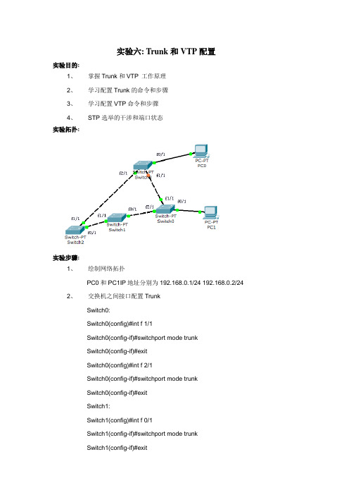
实验六: Trunk和VTP配置实验目的:1、掌握Trunk和VTP 工作原理2、学习配置Trunk的命令和步骤3、学习配置VTP命令和步骤4、STP选举的干涉和端口状态实验拓扑:实验步骤:1、绘制网络拓扑PC0和PC1IP地址分别为192.168.0.1/24 192.168.0.2/242、交换机之间接口配置TrunkSwitch0:Switch0(config)#int f 1/1Switch0(config-if)#switchport mode trunkSwitch0(config-if)#exitSwitch0(config)#int f 2/1Switch0(config-if)#switchport mode trunkSwitch0(config-if)#exitSwitch1:Switch1(config)#int f 0/1Switch1(config-if)#switchport mode trunkSwitch1(config-if)#exitSwitch1(config)#int f 1/1Switch1(config-if)#switchport mode trunkSwitch1(config-if)#exitSwitch2:Switch2(config)#int f 0/1Switch2(config-if)#switchport mode trunkSwitch2(config-if)#exitSwitch2(config)#int f 1/1Switch2(config-if)#switchport mode trunkSwitch2(config-if)#exitSwitch3:Switch3(config)#int f 1/1Switch3(config-if)#switchport mode trunkSwitch3(config-if)#exitSwitch3(config)#int f 2/1Switch3(config-if)#switchport mode trunkSwitch3(config-if)#exit3、VTP的配置。
(精选)利用交换机VTP协议实验来配置VLAN

利用交换机VTP协议实验来配置VLAN一、VTP介绍VTP(VLAN Trunking Protocol):是VLAN中继协议,也被称为虚拟局域网干道协议。
它是思科私有协议。
作用是十几台交换机在企业网中,配置VLAN工作量大,可以使用VTP协议,把一台交换机配置成VTP Server, 其余交换机配置成VTP Client,这样他们可以自动学习到server 上的VLAN 信息。
VTP模式有3种服务器模式(Server)客户机模式(Client)透明模式(Transparent)Server(服务器)模式——可以学习转发、可以添加删除或修改VLAN信息Client(客户机)模式——可以学习转发、但不可以添加删除或修改Transparent(透明)模式——不学习,但可以转发VLAN信息;可以创建或删除VLAN,只在本地有效,不影响其它路由器。
新交换机出厂时的默认配置是预配置为VLAN1,VTP 模式为服务器。
VTP协议只能学习到VLAN的信息,并不能学习到端口划分的信息配置命令若给VTP配置密码,那么本域内的所有交换机的VTP密码必须保持一致。
创建VTP域命令思科IOS系统switch(config)#vtp domain DOMAIN_NAME配置交换机的VTP模式三种模式server client transparent(透明模式)switch(config)# vtp mode server | client | transparent配置VTP口令switch (config) # vtp password PASSWORD配置VTP修剪能够减少中继端口上不必要的广播信息量,在模拟器中无此命令switch (config) # vtp pruning配置VTP版本switch (config) # vtp version 2(默认是版本1) ,客户机不可以配置ver 2查看VTP配置信息switch# show vtp status在三层路由器加了一块二层档板时,命令环境改变。
- 1、下载文档前请自行甄别文档内容的完整性,平台不提供额外的编辑、内容补充、找答案等附加服务。
- 2、"仅部分预览"的文档,不可在线预览部分如存在完整性等问题,可反馈申请退款(可完整预览的文档不适用该条件!)。
- 3、如文档侵犯您的权益,请联系客服反馈,我们会尽快为您处理(人工客服工作时间:9:00-18:30)。
交换机VLAN、TRUNK 、VTP 配置1.配置CISCO 二层交换机的IP 地址(catalyst 2950 为例)SW1(config)#int vlan 1 //进入管理接口interface vlan 1SW1(config-if)#ip address 11.1.1.2 255.255.255.0 //配置IP 地址SW1(config-if)#no shutdownSW1(config-if)#exitSW1(config)#ip default-gateway 11.1.1.1 //配置网关,可通过show run 查查看所配置的IP 地址:SW1#show int vlan 1Vlan1 is up, line protocol is upHardware is CPU Interface, address is 0008.20ff.6400 (bia 0008.20ff.6400)Internet address is 11.1.1.2/242.配置交换机的端口速度和双工(Speed and Duplex)SW1(config)#interface fa0/1SW1(config-if)#speed {10 | 100 | auto} //10M/100M/自适应SW1(config-if)#duplex {auto | full | half} //自适应/全双工/半双工一般情况下,交换机两端的端口速度和双工要匹配,这样通信质量才能得到保证,在相同厂家的产品(比如说Cisco 的交换机互连)中端口协商不用配置一般不会有什么问题,可以通过show interface 查看端口的速度和双工。
通常在不同厂家的产品中(比如说Cisco 和华为互连)如果通过查看发现端口速度和双工不匹配,可以通过手工配置来解决。
如图:通过show interface 查看端口的速度和双工:SW1#show interfaces fastEthernet 0/24FastEthernet0/24 is up, line protocol is up (connected)Hardware is Fast Ethernet, address is 0008.20ff.6418 (bia 0008.20ff.6418)MTU 1500 bytes, BW 100000 Kbit, DLY 100 usec,reliability 255/255, txload 1/255, rxload 1/255Encapsulation ARPA, loopback not setKeepalive set (10 sec)Full-duplex, 100Mb/s, media type is 100BaseTXinput flow-control is unsupported output flow-control is unsupportedARP type: ARPA, ARP Timeout 04:00:00Last input 00:00:03, output 00:00:00, output hang never注:CISCO 交换机端口默认值:Auto-duplex, Auto-speed, media type is 100BaseTX Cisco 设备配置端口速度(speed)和双工(duplex)命令:SW1(config)#interface fastEthernet 0/24SW1(config-if)#speed ?10 Force 10 Mbps operation ----------------------------注:强制速度为10M100 Force 100 Mbps operation---------------------------注:强制速度为100Mauto Enable AUTO speed configuration -----------------注:速度自动协议(默认值)SW1(config-if)#duplex ?auto Enable AUTO duplex configuration ----------------注:自动协商双工full Force full duplex operation ---------------------------注:强制为全双工half Force half-duplex operation --------------------------注:强制为半双工3.设置永久MAC 地址不过期SW1(config)#mac-address-table static mac_addr {vlan vlan_id} [interface int1 [int2 ... int15]] SW1(config)#mac-address-table static 1111.1111.a111 vlan 1 interface f0/1配置后show mac-address-table 可以看到静态添加的MAC 地址1111.1111.a111SW1#show mac-address-tableVlan Mac Address Type Ports---- ----------- -------- -----All 000f.72db.4ec0 STATIC CPU1 1111.1111.a111 STATIC Fa0/14.管理MAC 地址表SW1#show mac-address-tableMac Address Table-------------------------------------------Vlan Mac Address Type Ports---- ----------- -------- -----All 000f.72db.4ec0 STATIC CPU1 0000.0c3f.0b05 DYNAMIC Fa0/121 0030.94e6.391d DYNAMIC Fa0/111 00e0.b05a.5bfe DYNAMIC Fa0/101 1111.1111.a111 STATIC Fa0/15.设置交换机端口的访问模式(三种) access /dynamic / trunkSW1(config-if)#switchport mode ?access Set trunking mode to ACCESS unconditionallydynamic Set trunking mode to dynamically negotiate access or trunk modetrunk Set trunking mode to TRUNK unconditionallySW1(config)#int fastEthernet 0/1SW1(config-if)#switchport mode access //设置FA0/1 为ACCESS 模式SW1(config-if)#switchport mode trunk //设置FA0/1 为TRUNK 模式SW1(config-if)#switchport mode dynamic auto //设置FA0/1 为自动直协商模式(默认) 交换机TRUNK 端口配置:1)一般交换机与交换机相连接的端口要设置为trunk 模式2 )如果是梳心交换机与非网管的交换机相连,梳心交换机端口设置为access 模式如下图:配置SW1:SW1(config)#int f0/24SW1(config-if)#no shutdownSW1(config-if)#switchport mode trunk //设置FA0/24 为TRUNK 模式配置SW2:SW2(config)#int f0/24SW2(config-if)#no shutdownSW2(config-if)#switchport mode trunk //设置FA0/24 为TRUNK 模式验证TRUNK 命令:Show interface trunkShow interface f0/24 switchportSW1#sho run int f0/24interface FastEthernet0/24switchport mode trunkSW1#show int trunkPort Mode Encapsulation Status Native vlanFa0/24 on 802.1q trunking 1SW1#show int f0/24 switchportName: Fa0/24Switchport: EnabledAdministrative Mode: trunkOperational Mode: trunkAdministrative Trunking Encapsulation: dot1qOperational Trunking Encapsulation: dot1qNegotiation of Trunking: OnAccess Mode VLAN: 1 (default)Trunking Native Mode VLAN: 1 (default)Voice VLAN: noneAdministrative private-vlan host-association: noneAdministrative private-vlan mapping: noneAdministrative private-vlan trunk native VLAN: noneAdministrative private-vlan trunk encapsulation: dot1qAdministrative private-vlan trunk normal VLANs: noneAdministrative private-vlan trunk private VLANs: noneOperational private-vlan: noneTrunking VLANs Enabled: ALLPruning VLANs Enabled: 2-1001Capture Mode DisabledCapture VLANs Allowed: ALLProtected: falseAppliance trust: noneSW1#SW2:SW2#sho run int f0/24interface FastEthernet0/24switchport mode trunkendSW2#show int trunkPort Mode Encapsulation Status Native vlanFa0/24 on 802.1q trunking 16.配置VLAN1).创建VLANSW1(config)#vlan 2 //创建VLAN2SW1(config)#name VLAN2 //命名为VLAN2,默认为vlan002,命名是可选命令2).将端口加入VLANSW1(config-if)#switchport mode access //设配端口为access 模式SW1(config-if)#switchport access vlan 2 //把端口加到vlan23).检查的命令Switch#show vlan例子:创建VLAN2 命令为widom ,创建VLAN3 命令为market把端口F0/4 加入VLAN2SW1#config tSW1(config)#vlan 2SW1(config-vlan)#name wisdomSW1(config-vlan)#exitSW1(config)#vlan 3SW1(config-vlan)#name marketSW1(config-vlan)#exitSW1(config)#int fas0/4SW1(config-if)#switchport mode accessSW1(config-if)#switchport access vlan 2可以同时把多个端口加入到相应VLANSW1(config)#interface range fastEthernet 0/10 – 15 //可以同时把多个端口加入到一个VLAN 里SW1(config-if-range)#switchport mode accessSW1(config-if-range)#switchport access vlan 3 //把端口10-15 都加入到VLAN3 里SW1#show vlan //检查VLAN 信息VLAN Name Status Ports---- -------------------------------- --------- -------------------------------1 default active Fa0/1, Fa0/5, Fa0/6, Fa0/7Fa0/8, Fa0/9, Fa0/16, Fa0/17Fa0/18, Fa0/19, Fa0/20, Fa0/21Fa0/22, Fa0/23, Fa0/242 wisdom active Fa0/43 market active Fa0/10, Fa0/11, Fa0/12Fa0/13, Fa0/14, Fa0/15SW1#7.配置VTP----VTP 技术使得在大型的网络里布置多个VLAN 变得简单.VTP 的配置步骤:1、配置Trunk (交换机和交换机相连的端口要设置为TRUNK)2、配置VTP DOMAIN3、配置VTP MODE4、配置VLAN5、将端口加入VLAN6、检查Switch#show interface xx/xx switchport //查看相应该接口的trunk 状态Switch#show vtp status //查看vtp 状态Switch#show vlan //查看VLAN配置SW1:SW1#configure terminalSW1(config)#interface fastEthernet 0/24SW1(config-if)#switchport mode trunkSW1(config-if)#no shutdownSW1(config-if)#exitSW1(config)#vtp domain wisdomDomain name already set to wisdom.SW1(config)#vtp mode serverDevice mode already VTP SERVER.SW1(config)#vtp password ciscoSetting device VLAN database password to ciscoSW1(config)#vtp pruning //配置VTP 的修剪,只要在SERVER 端配置就行. Pruning switched onSW1#sho vtp statusVTP Version : 2Configuration Revision : 1Maximum VLANs supported locally : 64Number of existing VLANs : 5VTP Operating Mode : ServerVTP Domain Name : wisdomVTP Pruning Mode : EnabledVTP V2 Mode : DisabledVTP Traps Generation : DisabledMD5 digest : 0xE8 0x5A 0x7D 0xB1 0x0E 0xBC 0xEB 0x1FConfiguration last modified by 11.1.1.2 at 3-1-93 02:56:31Local updater ID is 11.1.1.2 on interface Vl1 (lowest numbered VLAN interface found) 创建VLAN2 VLAN3 VLAN4 VLAN5SW1(config)#vlan 2SW1(config-vlan)#vlan 3SW1(config-vlan)#vlan 4SW1(config-vlan)#vlan 5SW1(config-vlan)#在SW1 上创建VLAN 后查看修订版本:SW1#show vtp statusVTP Version : 2Configuration Revision : 5Maximum VLANs supported locally : 128Number of existing VLANs : 9VTP Operating Mode : ServerVTP Domain Name : wisdomVTP Pruning Mode : EnabledVTP V2 Mode : DisabledVTP Traps Generation : DisabledMD5 digest : 0x9C 0x64 0xD6 0x44 0x5E 0x54 0x9E 0xFCConfiguration last modified by 11.1.1.2 at 3-1-93 02:59:04Local updater ID is 11.1.1.2 on interface Vl1 (lowest numbered VLAN interface found) 在交换机SW1 上检查已创建的VLANSW1#sho vlanVLAN Name Status Ports---- -------------------------------- --------- -------------------------------1 default active Fa0/1, Fa0/5, Fa0/6, Fa0/7Fa0/8, Fa0/9, Fa0/16, Fa0/17Fa0/18, Fa0/19, Fa0/20, Fa0/21Fa0/22, Fa0/23, Fa0/242 VLAN0002 active3 VLAN0003 active4 VLAN0004 active5 VLAN0005 active检查trunk 端口:SW1#show interfaces fastEthernet 0/24 switchportName: Fa0/24Switchport: EnabledAdministrative Mode: trunkOperational Mode: trunkAdministrative Trunking Encapsulation: dot1qOperational Trunking Encapsulation: dot1qNegotiation of Trunking: OnAccess Mode VLAN: 1 (default)Trunking Native Mode VLAN: 1 (default)Voice VLAN: noneAdministrative private-vlan host-association: noneAdministrative private-vlan mapping: noneAdministrative private-vlan trunk native VLAN: noneAdministrative private-vlan trunk encapsulation: dot1qAdministrative private-vlan trunk normal VLANs: noneAdministrative private-vlan trunk private VLANs: noneOperational private-vlan: noneTrunking VLANs Enabled: ALLPruning VLANs Enabled: 2-1001Capture Mode DisabledCapture VLANs Allowed: ALLProtected: falseAppliance trust: none配置SW2:Switch#Switch#config tEnter configuration commands, one per line. End with CNTL/Z.SW2(config)#hostname SW2SW2(config)#int fastEthernet 0/24SW2(config-if)#switchport mode trunkSW2(config-if)#exitSW2(config)#vtp domain wisdomChanging VTP domain name from test to wisdomSW2(config)#vtp mode clientSetting device to VTP CLIENT mode.SW2(config)#vtp password ciscoSetting device VLAN database password to ciscoSW2(config)#查看F0/24 的trunk 状态:SW2#show interfaces fastEthernet 0/24 switchport Name: Fa0/24Switchport: EnabledAdministrative Mode: trunkOperational Mode: trunkAdministrative Trunking Encapsulation: dot1q Operational Trunking Encapsulation: dot1q Negotiation of Trunking: OnAccess Mode VLAN: 1 (default)Trunking Native Mode VLAN: 1 (default)Voice VLAN: noneAdministrative private-vlan host-association: none Administrative private-vlan mapping: none Administrative private-vlan trunk native VLAN: none Administrative private-vlan trunk encapsulation: dot1q Administrative private-vlan trunk normal VLANs: none Administrative private-vlan trunk private VLANs: none Operational private-vlan: noneTrunking VLANs Enabled: ALLPruning VLANs Enabled: 2-1001Capture Mode DisabledCapture VLANs Allowed: ALLProtected: falseAppliance trust: none查看VTP 状态:SW2#show vtp statusVTP Version : 2Configuration Revision : 5Maximum VLANs supported locally : 128Number of existing VLANs : 9VTP Operating Mode : ClientVTP Domain Name : wisdomVTP Pruning Mode : EnabledVTP V2 Mode : DisabledVTP Traps Generation : DisabledMD5 digest : 0x9C 0x64 0xD6 0x44 0x5E 0x54 0x9E 0xFCConfiguration last modified by 11.1.1.2 at 3-1-93 02:59:04----------此处可以看到SW2 的VLAN 信息是从SW1-11.1.1.2 同步过来的SW2#show vlanVLAN Name Status Ports---- -------------------------------- --------- -------------------------------1 default active Fa0/2, Fa0/3, Fa0/4, Fa0/5Fa0/6, Fa0/7, Fa0/8, Fa0/9Fa0/10, Fa0/11, Fa0/12, Fa0/13Fa0/14, Fa0/15, Fa0/16, Fa0/17Fa0/18, Fa0/19, Fa0/20, Fa0/21Fa0/22, Fa0/23, Fa0/242 VLAN0002 active3 VLAN0003 active4 VLAN0004 active5 VLAN0005 active实验结果:SW2 不用配置VLAN,已同步了SW1 的VLAN 信息.实验成功SW2 同步VTP SERVER 的VLAN 后,接下来的操作就是安要求把相应的端口加入到相应的VLAN。