氧气过滤器的详细资料
氧气过滤器说明书
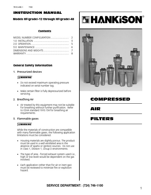
17610.490.1 7/00INSTRUCTION MANUALSERVICE DEPARTMENT: (724) 746-1100Models HF(grade)-12 through HF(grade)-48ContentsMODEL NUMBER CONFIGURATION ..........................21.0 INSTALLATION ...................................................32.0 OPERATION.......................................................53.0 MAINTENANCE .................................................6DIMENSIONS AND WEIGHTS.....................................7WARRANTY..............................................................8General Safety Information1.Pressurized devices•Do not exceed maximum operating pressure indicated on serial number tag.•Make certain filter is fully depressurized before servicing.2.Breathing Air•Air treated by this equipment may not be suitablefor breathing without further purification. Refer to OSHA standard 1910.134 for breathing air requirements.3.Flammable gasesWhile the materials of construction are compatible with many flammable gases, the following application limitations must be considered:•Housing materials are slightly porous. The product must be used in a well ventilated area in theabsence of sparks or ignition sources. Do not usein Class 1, Division 1, Group D environments.•The type of area - forced exhaust system used (i.e.,high or low level) would be dependent on the gas involved.•Each application (other than for air or inert gas)must be reviewed to minimize fire or explosion hazard.2Grade IdentificationFilter grade can be identified by the third digit of the model number. In addition, elements with a foam outer sleeve can be identified by color(1) Filter Grade17 -Particulate filter11 -Mechanical Separator 9 -Separator/filter 7 -Air Line Filter5 -High Efficiency Oil Removal Filter 3 -Ultra High Efficiency Oil Removal Filter 1 -Oil Vapor Removal Filter(3) Connection Sizes6 - 3/4” NPTF or 6B - 3/4” BSP or 8 - 1” NPTF 8B - 1 BSP 8 - 1” NPTF or 8B - 1 BSP or10 - 1-1/4” NPTF or 10B - 1-1/4” BSP or 12 - 1-1/2” NPTF 12B - 1-1/2” BSP 16 - 2” NPTF or 16B - 2” BSP or 20 - 2-1/2” NPTF 20B - 2-1/2” BSP (2) Housing Number Capacityscfm [m 3/min] @100 psig [7 kgf/cm 2]1220 [0.57]1635 [1.00]2060 [1.72]24100 [2.9]28170 [4.9]44625 [18]48780 [22]3 - 3/8” NPTF or 3B - 3/8” BSP or4 - 1/2” NPTF 4B - 1/2” BSP 20 - 2-1/2” NPTF20B - 2-1/2” BSP40 485 [14]32250 [7.2]36375 [11] Grade Description TypeOuter foam color17Particulate filter One micron solid particulate filter none 11Mechanical Separator Impaction type separatornone 9Separator/filterMechanical separator and 3 micron coalescer none 7General purpose air line filter 1 micron coalescernone 5High efficiency oil removal filter High efficiency (99.99+%) coalescer Red 3Ultra high efficiency oil removal filter Ultra high efficiency (99.999+%) coalescer Blue 1Oil vapor removal filterActivated carbon adsorberGreenModel Number ConfigurationHF(1)-(2)-(3) (4)1.Filter Grade is indicated in space (1).2.Housing Number is indicated in space (2).3.Connection Size is indicated in space (3)4.FeaturesD = Internal Automatic Drain Mechanism P = Differential Pressure Slide Indicator G = Differential Pressure Gauge Indicator L = Liquid Level IndicatorS = Corrosion Proof Stainless Steel Element X = External Drain AdapterExample: A Grade 5 high efficiency oil removal filter with a capacity of 100 scfmand 3/4” NPTF connections would be configured as: HF 5-24-6DGLn (4) FeaturesD -Internal Automatic Drain Mechanism P -Differential Pressure Slide Indicator G -Differential Pressure Gauge Indicator L -Liquid Level IndicatorS -Corrosion Proof Stainless Steel Element X -External Drain Adapter1.0 InstallationA.Where Used/Air Quality After Filtration34D.Drain provisions1.Internal Automatic Drains - Drain lineThe bottom of internal automatic drains are provided with 1/8" (inside threads) for connection of a drain line if desired.2.External Auto Drains - External auto drains may beadded as follows:Models with housings 34 through 48 - remove internal drain and install adapter (available from factory). Adapter outlet connection is 1/8" (inside threads).b.Threaded headsUse four carriage bolts, nuts and o-ring (sold as kit).Remove black plastic top caps, apply generous amount of lubricant to o-ring, install o-ring in groove, and install bolts and nuts.5.Direct filter-to-filter (modular) connection - Filterheads may be joined without using a pipe nipplea.Bayonet type heads - Use two (2) modular connec-tors, o-ring, and four (4) socket head cap screws (sold as kit)Remove black plastic top cap, apply generous amount of lubricant to o-ring, install o-ring in groove, and insert connectors. Screw connectors to head using socket head cap screws.NOTE: Make certain flow direction through filters is correct (observe pin hole used for aligning top caps).Models 11,9,7,5,3,1 - when hole is on side closest to you,inlet is to left. Model 17 - when hole is on the side farther from you, inlet is to left.NOTE: Lubricate o-ring with generous amount of lubri-cant before installation.6.Isolation valves and by-pass piping - For ease ofservice, isolation and by-pass valves are desirable. In critical applications, two filters installed in parallel may be necessary to avoid interruption of air supply.C.Piping1.Before installing, blow out pipe line to remove scaleand other foreign matter.2.This unit has DRYSEAL pipe threads; use pipe com-pound or tape sparingly to male threads only.3.Mounting (Grades 11,9,7,5,3) - mount so that inletand outlet connections are horizontal (filter bowl vertical) to ensure proper liquid drainage.4.Flow Direction - install so that the air flow is in thedirection of arrows on the filter head. NOTE: Grade 17 flows from outside to inside ofelement. All other grades flow from inside to outside of element. Observe flow arrows on cap.52.0 Operationber Tag.NOTE: Maximum Operating Temperature - 150°F , 66°C.Liquid filtration above 120°F , 49°C is not recommended since there is typically oil present in a vapor state which passes through the filter and condenses downstream.NOTE: Grade 1 - If operated above 100°F , 38°C mayexperience less than 1000 hours of life because of greater oil vapor content.A. Liquid Draining - Grades 11, 9, 7, 5, 3NOTE: Collected liquids must be removed to ensure proper operation.NOTE: Depressurize slowly, to avoid filter element dam-age.1.Manual Drain - Turn to your right (clockwise) to openand to your left (counterclockwise) to close.2.Automatic Drain - Liquids will automatically dischargewhen sufficient accumulation occurs.a.Internally Mounted Auto Drains - These drains may be manually drained by turning to your right(clockwise) to open and to your left (counterclock-wise) to close.NOTE: Manually drain internal auto drains daily to verify drain function.Grades 11,9,7,5,31. Check to see that filter is installed level to insure proper drainage.2. Check that manual drains are drained periodically or that automatic drains are functioning.3. On models with Liquid Level Sight glass - Check that liquid level is below top of Sight glass.Grade 11.Check for an oily smell by opening the manual valve. Ifan oily smell exists, the following should be checked:a.Filter element adsorption capacity exhaustedb.Leak across element o-ring sealc.Leak through element due to physical damaged.Presence of liquids because of lack of or failure of prefilterse.Flow, pressure and temperatures outside design conditionsf.Presence of gaseous impurities which cannot be adsorbed activated carbon filter.C. Flow CapacityMaximum air flow for the various filters at 100 psig(7 kgf/cm 2) is indicated in Table 1. To determine maximum air flows at inlet pressures other than 100 psig(7 kgf/cm 2), multiply flow from Table 1 by air flow correc-tion factor from Table 2 that corresponds to the mini-mum operating pressure at the inlet of the filter.NOTE: Filters should not be selected by pipe size. Select using flow rate and operating pressure only.B. Operational Checkpoints All GradesCheck flow, pressure, and temperature to makecertain filter is being operated within design conditions.Grades 17,11,9,7,5,3Check pressure drop across the filter1. Pressure differential in excess of 10 psi (0.7 kgf/cm 2) -pressure indicator in red area - indicates that the filter sleeve or element should be replaced.NOTE: Element should be changed annually or when indicator changes to red, whichever occurs first.NOTE: Pressure drop should never exceed 50 psi (3.5 kgf/cm 2).2. Check for sudden reduction in pressure drop. This might indicate:a. Possible leak across element o-ring sealb. Leak through the element due to physical damageTable 1 - Maximum Flow @100 psig [7 kgf/cm 2]Housing scfm [m 3/min]1220 [0.57]1635 [1.00]2060 [1.72]24100 [2.9]28170 [4.9]32250 [7.2]36375 [11]40485 [14]44625 [18]48780 [22]OPEN ( TO RIGHT )Minimum Inlet PressureTable 2 - Air Flow Correction Factorpsig 2030406080100120150200250300kgf/cm 21.42.1 2.8 4.2 5.67.08.410.614.117.621.1Correction Factor 0.300.390.480.650.821.001.17 1.431.87 2.31 2.74n63.0 MaintenanceA.When to Replace Filter ElementNOTE: Grades 17,7,5,3,1 - complete element is replaced;Grade 9 - unless separator core is damaged outer sleeve only is replaced.1.Grade 17 (particulate filter)Initial drop: 1 psi (0.07 kgf/cm 2). Pressure drop increases as element loads with solid particles. Re place when pressure drop reaches 10 psi (0.7 kgf/cm 2)(indicator in red area) or annually, whichever occurs first.2.Grade 11 (mechanical separator)Element should not require replacement unlessphysically damaged. If sludge accumulates, element can be removed and cleaned with soap and water.3.Grades 9,7,5,3a.Initial (dry) pressure drop: 1 psi (0.07 kgf/cm 2) to 2psi (0.14 kgf/cm 2)b.Operating pressure drop: As filter becomes liquid loaded (wetted), pressure drop will increase to 2 to 6 psi (0.14 to 0.42 kgf/cm 2). Further pressure drop occurs as element loads with solid particles.c. FOR MAXIMUM FILTRATION EFFICIENCY, REPLACE ELEMENT WHEN PRESSURE DROP REACHES 10 PSI (0.7 KGF/CM 2) (INDICATOR IN RED AREA) OR ANNU-ALLY , WHICHEVER OCCURS FIRST.NOTE: Pressure drop may temporarily increase when flow is resumed after flow stoppage. Pressure drop should return to normal within one hour.NOTE: Grades 5 and 3 - During normal operation bottom of foam sleeve will have a band of oil. Spotting above the band indicates that liquids are accumulating faster than they can be drained and that prefiltration is required.4.Grade 1 (activated carbon filters)a.Adsorption capacity - 1000 hours at rated capacity .Element life is exhausted when odor can be de-tected downstream of the filter.B. Procedure for Element Replacementbeen depressurized before disassembly, an audible alarm will sound when the bowl begins to be removed from the head. If this occurs, stop disassembly, isolate and com-pletely depressurize filter before proceeding.1.Isolate filter (close inlet and outlet valves if installed) orshut off air supply.2.Depressurize filter by slowly opening manual drainvalve.3.Remove bowla.For models 12 through 28 - bayonet mount - push bowl up, turn bowl 1/8th turn to your left, and pull bowl straight downb.For models 32 through 48 - threaded bowls -unscrew bowl from head using hand, strap wrench or C spanner.4.Clean filter bowl 5.Replace elementa.Replacing complete element1) Pull off old element and discard.2) Make certain o-ring inside top of replacement element is in place and push element onto filter head. For Housing sizes 40 to 48, place element in bowl and secure with centering device.NOTE: Grades 5, 3, and 1 - Do not handle elements by outside foam cover. Handle by bottom end cap only.b.Grade 9 - replacing sleeve only1) Pull element straight down to remove.2) Remove bolt and bottom cap and remove disposable filter sleeve.3) Clean separator core with soap and water if necessary.4) Slide new filter sleeve over separator core and replace bottom cap and hand tighten bolt.5) Make certain o-ring inside top of element is in place and push element onto filter head.6.After making certain that o-ring inside top of bowl(and on bayonet mount heads, wave spring) are in place, reassemble bowl to head.NOTE: Make certain o-ring is generously lubricated.NOTE: Wave spring ends should be pointed down to prevent the wave spring from interfering with reassem-bly.NOTE: Threaded bowl to head connection, generously lubricate threads with a high grade/temperature lubricant good for 150°F , 66°C.C. Auto Drain MechanismIt is recommended that drain mechanism be replaced annually.Grade 9 - Sleeve Replacement All Grades - Element Replacement7Dimensions and Weights"52m m )S i z e s H F (G r a d e )-24, 28S I N L E I N S i z e s H F (G r a d e ) 32, 36S i z e s H F (G r a d e ) 40, 44, 48F i l t e r T y p e H F (G r a d e )-12162024283236404448R e p l a c e m e n t E l e m e n t E (G r a d e )-12 o r 12S16 o r 16S20 o r 20S24 o r 24S28 o r 28S32 o r 32S36 o r 36S40 o r 40S44 o r 44S48 o r 48SN o m i n a l A i r F l o w s c f m @100 p s i g (m 3/m i n @ 7.0 b a r )20 (.57)35 (1.00)60 (1.72)100 (2.9)170 (4.9)250 (7.2)375 (11)485 (14)625 (18)780 (22)I n /O u t C o n n e c t i o n N P T o r B S P3/8, 1/23/8, 1/23/8, 1/23/4, 13/4, 11, 1-1/4, 1-1/21, 1-1/4, 1-1/22, 2-1/22-1/22-1/2"A "4.13 (105)4.13 (105)4.13 (105)5.25 (133)5.25 (133)6.44 (164)6.44 (164)7.63 (194)7.63 (194)7.63 (194)"B "8.15 (207)10.05 (255)12.40 (316)13.32 (338)17.57 (446)20.80 (528)25.29 (642)29.08 (739)34.83 (885)40.96 (1040)"C "6.40 (163)8.59 (224)10.97 (285)11.74 (298)15.99 (406)18.98 (482)23.47 (596)26.83 (681)32.58 (827)38.71 (983)"D "3.00 (76)3.00 (76)3.00 (76)3.50 (89)3.50 (89)4.00 (102)4.00 (102)4.00 (102)4.00 (102)4.00 (102)W e i g h t4.14 (1.88)8.1 (3.67)8.5 (3.86)6.3 (2.9)6.9 (3.1)10.2 (4.63)11.3 (5.13)28 (12.70)33 (14.97)38 (17.24)M a x i m u m W o r k i n g P r e s s u r eH o u s i n g - 300 p s i g , 21.1 k g f /c m 2H o u s i n g - 300 p s i g , 21.1 k g f /c m 2M o d e l s w i t h I n t e r n a l D r a i n o r M o d e l s w i t h I n t e r n a l D r a i n o r L i q u i d l e v e l i n d i c a t o r - 250 p s i g , 17.6 k g f /c m 2L i q u i d l e v e l i n d i c a t o r - 250 p s i g , 17.6 k g f /c m 2M a x i m u m O p e r a t i n g T e m p e r a t u r e150°F , 66°C150°F , 66°CH e a d M a t e r i a lZ i n c A l u m i n u mA l u m i n u mB o w l M a t e r i a lA l u m i n u m Z i n cA l u m i n u mA l u m i n u mS t e e lL i q u i d L e v e l I n d i c a t o r M a t e r i a lI s o p l a s t I s o p l a s t -----N O T E : D i m e n s i o n s a n d W e i g h t s a r e f o r r e f e r e n c e o n l y . R e q u e s t c e r t i f i e d d r a w i n g s f o r c o n s t r u c t i o n p u r p o s e s .n8Division Of Hansen Inc.Canonsburg, P A 15317-1700 U.S.A.Tel 724-745-1555 Fax 724-745-6040************************SERVICE DEPARTMENT: (724) 746-1100WARRANTYThe manufacturer warrants the product manufactured by it, when properly installed, operated, applied, and main-tained in accordance with procedures and recommendations outlined in manufacturer’s instruction manuals, to be free from defects in material and workmanship for a period of one (1) year from date shipment to the buyer by the manufacturer or manufacturer’s authorized distributor provided such defect is discovered and brought to the manufacturer’s attention within the aforesaid warranty period.The manufacturer will repair or replace any product or part determined to be defective by the manufacturer within the warranty period, provided such defect occurred in normal service and not as a result of misuse, abuse, neglect or accident. Normal maintenance items requiring routine replacement are not warranted. The warranty covers parts and labor for the warranty period. Repair or replacement shall be made at the factory or the installation site, at the sole option of the manufacturer . Any service performed on the product by anyone other than the manufacturer must first be authorized by the manufacturer .Unauthorized service voids the warranty and any resulting charge or subsequent claim will not be paid.Products repaired or replaced under warranty shall be warranted for the unexpired portion of the warranty applying to the original product.The foregoing is the exclusive remedy of any buyer of the manufacturer’s product. The maximum damages liability of the manufacturer is the original purchase price of the product or part.THE FOREGOING WARRANTY IS EXCLUSIVE AND IN LIEU OF ALL OTHER WARRANTIES, WHETHER WRITTEN, ORAL, OR STATU-TORY , AND IS EXPRESSED IN LIEU OF THE IMPLIED WARRANTY OF MERCHANTABILITY AND THE IMPLIED WARRANTY OF FITNESS FOR A PARTICULAR PURPOSE. THE MANUFACTURER SHALL NOT BE LIABLE FOR LOSS OR DAMAGE BY REASON OF STRICT LIABILITY IN TORT OR ITS NEGLIGENCE IN WHATEVER MANNER INCLUDING DESIGN, MANUFACTURE OR INSPECTION OF THE EQUIPMENT OR ITS FAILURE TO DISCOVER, REPORT, REPAIR, OR MODIFY LATENT DEFECTS INHERENT THEREIN.THE MANUFACTURER, HIS REPRESENTATIVE OR DISTRIBUTOR SHALL NOT BE LIABLE FOR LOSS OF USE OF THE PRODUCT OR OTHER INCIDENTAL OR CONSEQUENTIAL COSTS, EXPENSES, OR DAMAGES INCURRED BY THE BUYER, WHETHER ARISING FROM BREACH OF WARRANTY , NEGLIGENCE OR STRICT LIABILITY IN TORT.The manufacturer does not warrant any product, part, material, component, or accessory manufactured by others and sold or supplied in connection with the sale of manufacturer’s products. 1/96AUTHORIZATION FROM THE SERVICE DEPARTMENT IS NECESSARY BEFORE MATERIAL ISRETURNED TO THE FACTORY OR IN-WARRANTY REPAIRS ARE MADE.。
氧气过滤器-YTG、YTG-A型氧气过滤器
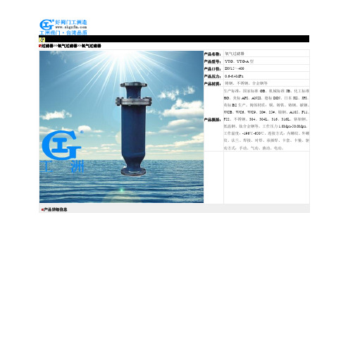
过滤器>>氧气过滤器>>氧气过滤器产品详细信息过滤器系列价格供用户或设计院工程项目做预算一、阀门的选型步骤1.明确阀门在设备或装置中的用途,确定阀门的工作条件:适用介质、工作压力、工作温度等等。
2.确定与阀门连接管道的公称通径和连接方式:法兰、螺纹、焊接等。
3.确定操作阀门的方式:手动、电动、电磁、气动或液动、电气联动或电液联动等。
4.根据管线输送的介质、工作压力、工作温度确定所选阀门的壳体和内件的材料:灰铸铁、可锻铸铁、球墨铸铁、碳素钢、合金钢、不锈耐酸钢、铜合金等。
5.确定阀门的型式:闸阀、截止阀、球阀、蝶阀、节流阀、安全阀、减压阀、蒸汽疏水阀、等。
6.确定阀门的参数:对于自动阀门,根据不同需要先确定允许流阻、排放能力、背压等,再确定管道的公称通径和阀座孔的直径。
7.确定所选用阀门的几何参数:结构长度、法兰连接形式及尺寸、开启和关闭后阀门高度方向的尺寸、连接的螺栓孔尺寸和数量、整个阀门外型尺寸等。
8.利用现有的资料:阀门产品目录、阀门产品样本等选型适当的阀门产品。
二、阀门的选型依据1.所选用阀门的用途、使用工况条件和操纵控制方式。
2.工作介质的性质:工作压力、工作温度、腐蚀性能,是否含有固体颗粒,介质是否有毒,是否是易燃、易爆介质,介质的黏度等等。
3.对阀门流体特性的要求:流阻、排放能力、流量特性、密封等级等等。
4.安装尺寸和外形尺寸要求:公称通径、与管道的连接方式和连接尺寸、外形尺寸或重量限制等。
⑤对阀门产品的可靠性、使用寿命和电动装置的防爆性能等的附加要求。
(在选定参数时应注意:如果阀门要用于控制目的,必须确定如下额外参数:操作方法、最大和最小流量要求、正常流动的压力降、关闭时的压力降、阀门的最大和最小进口压力。
)根据上述选型阀门的依据和步骤,合理、正确地选型阀门时还必须对各种类型阀门的内部结构进行详细了解,以便能对优先选用的阀门做出正确的抉择。
管道的最终控制是阀门。
医用氧使用说明书

规格型号:XSY系列出厂编号:出厂日期:杭州苏宏医疗器械有限公司目录一、医用分子筛制氧设备安全操作规程------------1二、医用分子筛制氧设备结构特性及工作原理---2三、医用分子筛制氧设备的技术特性---------------- 3四、医用分子筛制氧设备的使用、操作--------------5五、医用分子筛制氧设备故障分析与排除----------11六、医用分子筛制氧设备日常保养和维修----------12 附录、制氧设备安全保护装置-------------------------13本医用分子筛制氧设备是国家医疗器械Ⅱ类产品,电气部分为Ⅰ类B型医用电器设备。
由杭州苏宏医疗器械有限公司制造。
执行标准:YZB/浙0611-2006本公司地址:浙江省临安市锦城街道畔湖路123号电话号码:0571-传真:0网址:电子信箱:E-mail: hzsuhong @ 邮编:311300一、医用分子筛制氧设备安全操作规程1. 严格遵守本《使用说明书》中所规定的操作规程;2. 机房内严禁烟火和堆放易燃物品;禁止在机房内吸烟。
3. 操作人员不经培训,不得上岗;4. 室内温度保持在5-38℃的范围内,确保设备正常运转;5. 开机前合上电源开关,按下控制柜试灯按钮,看指示灯是否正常;6. 每隔一小时对设备巡视一次,发生异常现象,查明原因,及时采取措施,,异常现象排除后才能再开机;7. 每二小时记录一次设备运行情况,出现故障应及时排除。
修复后要及时记录;8. 压缩机的进气口空气过滤器每周清洗一次,并且每周检查压缩机是否缺油;9. 缓冲罐后的调节阀调试时已调整好,严禁随意调整该调节阀;10. 停机后关闭所有阀门, 拉掉电源总闸;11. 保持制氧设备清洁干净。
二、医用分子制氧筛备结构特性及工作原理2.1 结构特征本医用分子筛制氧设备由国家医疗器械Ⅱ类产品制氧设备主机和空气压缩机、高效冷干机、高效过滤器等组成。
化工装置中氧气过滤器的作用
化工装置中氧气过滤器的作用下载提示:该文档是本店铺精心编制而成的,希望大家下载后,能够帮助大家解决实际问题。
文档下载后可定制修改,请根据实际需要进行调整和使用,谢谢!本店铺为大家提供各种类型的实用资料,如教育随笔、日记赏析、句子摘抄、古诗大全、经典美文、话题作文、工作总结、词语解析、文案摘录、其他资料等等,想了解不同资料格式和写法,敬请关注!Download tips: This document is carefully compiled by this editor. I hope that after you download it, it can help you solve practical problems. The document can be customized and modified after downloading, please adjust and use it according to actual needs, thank you! In addition, this shop provides you with various types of practical materials, such as educational essays, diary appreciation, sentence excerpts, ancient poems, classic articles, topic composition, work summary, word parsing, copy excerpts, other materials and so on, want to know different data formats and writing methods, please pay attention!标题:化工装置中氧气过滤器的作用引言在化工装置中,氧气过滤器扮演着至关重要的角色。
初中效过滤器产品介绍

(一)化纤袋式空气过滤器(中效袋式空气过滤网)产品特性:1、以镀锌铁或铝合金为结构外框。
2、每个滤袋间一金属条固定,增加强度,并防止滤袋于高风速时,因风切之摩擦力而破裂。
3、每个滤袋均有六道隔片平均分布于袋宽中,防止滤袋承受风压时过度膨胀、相互遮蔽,降低有效过滤面积与效率。
4、每个滤袋边均采用超声波方式熔合,具有良好之气密性及结合强度,不产生漏气或裂。
5、采用超细合成纤维以特殊织法制成,避免旧式玻璃纤维材料所可能对人体造成的不适。
6、滤材内含静电纤维,对次微米粉尘过滤效率特别良好, 具有高捕尘能力,高粉尘载量及高透气性,高使用寿命。
7、有35%、45%、65%、85%、95%、98%即G4、F5、F6、F7、F8、F9六种效率的袋型滤网可以选择。
性能参数:效率外形尺寸(mm) 袋数(pcs)过滤面积(m2)初阻力(Pa)建议风量(m3/h)35% 287×592×550 3 2.14 40 1700 490×592×550 5 3.58 40 2800 592×592×550 6 4.29 40 340045% 287×592×600 3 2.34 45 1800 490×592×600 5 3.9 45 3000 592×592×600 6 4.68 45 360065% 287×592×600 3 2.34 60 1700 490×592×600 5 3.9 60 2800 592×592×600 6 4.68 60 340085% 287×592×600 3 2.34 95 1700 490×592×600 5 3.9 95 2800 592×592×600 6 4.68 95 340095% 287×592×600 3 2.34 126 1700 490×592×600 5 3.9 126 2800 592×592×600 6 4.68 126 3400注:接受客户非标定做,欢迎来电咨询!上海台旭净化设备有限公司联系人:周立波先生(工程师)电话: 传真:E-mail:Q Q:85344587地址:上海市松江区泗陈公路518弄10幢(二)中效玻纤袋式空气过滤网(玻纤袋式空气过滤器)简介玻纤袋式空气过滤器发达国家多年的调查研究和经验表明,玻璃纤维袋式过滤器是用户最经济有效的选择。
制氧机技术参数
制氧机技术参数
一.结构特征
产品结构有压缩机、吸附塔、流量指示器、湿化器、换向阀、电路板、外壳、连接管、过滤器、鼻氧管、雾化组件组成。
二.制氧原理
以220V电源为动力源,空气为原料,采用优质分子筛,在常温下通过变压吸附分离法(PSA法),制取符合医用氧标准的高纯度氧气。
三.主要技术指标
1.最大推荐流量:3L/min
2.出口标称压力为零和7kPa时的流量范围:0.5~3L/min
3.在最大推荐流量时,施加7kP9a的背压,流量变化:0.5L/min
4.出口标称压力为零时的氧浓度(在初始开机30min内,达到规定的浓度水平):氧流量0.5~3L/min时,氧浓度≥90%
5.输出压力:20~50kPa
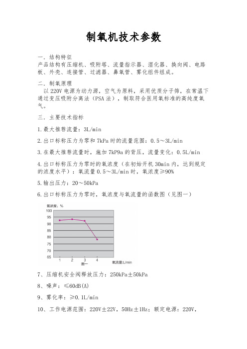
6.出口标称压力为零时,氧浓度与氧流量的函数图(见图一)
7、压缩机安全阀释放压力:250kPa±50kPa
8、噪声:≤60dB(A)
9、雾化率:≥0.1L/min
10、工作电源范围:220V±22V,50Hz±1Hz;额定电源:220V,
50Hz
11、输入功率:380VA
12、海拔高度:海平面至1828米时不会降低氧浓度,从1828米至4000米时效率低于90%
13、安全系统:
电流过载或连线松脱,报警停机;
压缩机高温,报警停机;
压力、循环故障、报警停机;
压缩机故障,报警停机;
低氧浓度,报警;。
氧气过滤器安全操作及保养规程

氧气过滤器安全操作及保养规程氧气过滤器是医学和工业领域常用的设备之一,它可以去除氧气中的杂质,确保患者或工人使用纯净的氧气。
然而,如果过滤器操作不当或保养不到位,可能会导致无法预测的风险。
本文将介绍氧气过滤器的安全操作及保养规程,以确保过滤器的正常运行和使用者的安全。
安全操作规程1. 根据说明书进行操作在使用氧气过滤器前,必须仔细阅读其说明书并按照说明书上的操作步骤进行操作。
氧气过滤器的不同型号和品牌,其操作步骤和注意事项可能会有所不同,一定要根据自己手头的设备来进行正确的操作。
2. 检查连接方式和阀门开关在连接氧气过滤器到氧气源和使用端时,一定要确保连接方式正确可靠,没有泄漏。
在启动氧气过滤器之前,应检查其连接处和阀门位置,确保阀门已关闭,过滤器处于关闭状态。
3. 观察压力表读数在启动氧气过滤器之后,要观察压力表的读数,确保氧气的压力在设备的设计范围内。
如压力过高或过低应立即停机排查。
4. 避免灰尘进入过滤器氧气过滤器上装有滤网和滤芯,在使用时要避免灰尘和污物进入过滤器内部。
在拆卸和更换滤芯时,也要注意防止空气中的灰尘进入过滤器内部。
5. 远离火源和电器在使用氧气过滤器时,必须远离火源和电器设备,以防发生火灾或安全事故。
不要使用明火和电器设备进行操作。
保养规程1. 定期更换滤芯滤芯是氧气过滤器的核心部件,长时间使用后会积累大量污染物。
根据使用时间和实际污染情况,需要定期更换滤芯。
更换滤芯时,要保证使用的滤芯型号正确,更换过程要注意防止进入灰尘和污物。
2. 清洗箱体和连接管路在更换滤芯的同时,可以对箱体和连接管路进行清洗。
当发现箱体内有积尘和污物时,可以使用清洁剂和水清洗箱体内部。
3. 定期检查连接为了保证氧气过滤器的连接为完好可靠,应定期检查连接部分,确保连接紧密无泄漏。
如果发现连接部位有泄漏现象,应立即排查并及时进行维修。
4. 存储环境和温度氧气过滤器的存储应放置在干燥、通风、无尘、无腐蚀气体的场所中,存储温度一般为+2℃~+45℃。
氧气过滤器过滤精度标准
氧气过滤器过滤精度标准一、概述氧气过滤器是一种用于过滤氧气中的杂质和有害物质的设备,常用于医疗、工业和实验室等领域。
过滤精度是衡量过滤器性能的重要指标之一,它直接影响到过滤效果和气体质量。
本标准主要对氧气过滤器的过滤精度进行规范和要求。
二、过滤精度标准1.颗粒过滤:要求过滤器对颗粒物的过滤效果达到95%以上,同时应具有较高的耐压能力和使用寿命。
2.气体吸附:要求过滤器对气体中的有害物质具有较高的吸附效果,如二氧化碳、硫化氢等,应能有效地提高氧气纯度。
3.微生物拦截:要求过滤器能够拦截气体中的微生物,如细菌、病毒等,以保障气体无菌或微生物含量符合标准。
4.气味过滤:要求过滤器能够过滤掉气体中的异味,如氨气、硫化氢等,使气体闻起来更加清新、无异味。
5.湿度控制:要求过滤器具有湿度控制功能,能够将气体湿度控制在一定范围内,以避免设备内部出现冷凝水或结露现象。
6.温度调节:要求过滤器具有温度调节功能,能够将气体温度调节到一定范围内,以保障设备的正常运行和使用效果。
7.精度等级:要求过滤器的精度等级达到一定的标准,如ISO 5级或更高,以确保过滤效果和气体质量。
8.材质选择:要求过滤器的材质符合相关标准和规定,如食品级材料或更高标准,以确保设备的可靠性和安全性。
9.结构优化:要求过滤器的结构设计合理、紧凑,易于维护和更换滤芯等部件,以提高设备的整体性能和使用寿命。
10.安全性设计:要求过滤器的设计符合相关安全标准,如防爆、防火等,以确保设备的安全性和稳定性。
三、结论氧气过滤器的过滤精度对于保障气体质量和设备正常运行至关重要。
本标准从颗粒过滤、气体吸附、微生物拦截、气味过滤、湿度控制、温度调节、精度等级、材质选择、结构优化和安全性设计等方面对氧气过滤器的过滤精度进行了规范和要求。
为了提高氧气过滤器的性能和使用效果,应严格按照本标准进行设计和制造。
- 1、下载文档前请自行甄别文档内容的完整性,平台不提供额外的编辑、内容补充、找答案等附加服务。
- 2、"仅部分预览"的文档,不可在线预览部分如存在完整性等问题,可反馈申请退款(可完整预览的文档不适用该条件!)。
- 3、如文档侵犯您的权益,请联系客服反馈,我们会尽快为您处理(人工客服工作时间:9:00-18:30)。
氧气过滤器是专为氧气管路设计的一种特殊过滤器,氧气过滤器由分流锥、过滤网管组成,水流推力主要起到气体分流,因而避免过滤网受正面引起的破裂;氧气过滤器是输送介质管道上不可缺少的一种装置,通常安装在减压阀、泄压阀、定水位阀或其它设备的进口端,用来消除介质中的杂质,以保护阀门及设备的正常使用。
当流体进入置有一定规格滤网的滤筒后,其杂质被阻挡,而清洁的滤液则由氧气过滤器出口排出,氧气过滤器当需要清洗时,只要将可拆卸的滤筒取出,处理后重新装入即可,因此,使用维护极为方便。
一、氧气过滤器性能规范:
二、氧气过滤器滤网规格:
三、氧气过滤器主要尺寸:
订货须知:
一、①氧气过滤器产品名称与型号②氧气过滤器口径③是否带附件以便我们的为您正确选型。
二、若已经由设计单位选定,请按氧气过滤器型号直接向我们沃托阀门销售部订购。
三、当使用的场合非常重要或环境比较复杂时,请您尽量提供氧气过滤器设计图纸和详细参数,由我们沃托阀门专家为您审核把关。
尊敬的客户:
欢迎您访问我们的网站首先感谢您对我们沃托阀门的关注,如果您对氧气过滤器产品、服务有任何建议或者疑问的话,请立即联系我们!我们一定会尽心尽力为您提供优质的服务!!!氧气过滤器、氧气过滤器图片、氧气过滤器原理、燃气过滤器、天然气过滤器、液化气过滤器/Products/T27/134.html 。