系列零部件手册
Rev. H 安装、维护与零部件手册:2100、2200、4100、6200、MPB系列顶部挂载驱动

851-257 Rev. HInstallation, Maintenance& Parts ManualTable of ContentsWarnings − General Safety 2. . . . . . . . . . . . . . . . . . . . Introduction 2. . . . . . . . . . . . . . . . . . . . . . . . . . . . . . . . Product Description 3. . . . . . . . . . . . . . . . . . . . . . . . . . Specifications 3. . . . . . . . . . . . . . . . . . . . . . . . . . . . . . . Gearmotors 3. . . . . . . . . . . . . . . . . . . . . . . . . . . . . . . 2200 Belt Speeds 4. . . . . . . . . . . . . . . . . . . . . . . . . . 2100, 4100 & 6200 Belt Speeds 5. . . . . . . . . . . . . . MPB Belt Speeds 6. . . . . . . . . . . . . . . . . . . . . . . . . . Installation 7. . . . . . . . . . . . . . . . . . . . . . . . . . . . . . . . . Required Tools 7. . . . . . . . . . . . . . . . . . . . . . . . . . . . Mounting 7. . . . . . . . . . . . . . . . . . . . . . . . . . . . . . . .Preventative Maintenance and Adjustment 10. . . . . . . Required Tools 10. . . . . . . . . . . . . . . . . . . . . . . . . . . Timing Belt Tensioning 10. . . . . . . . . . . . . . . . . . . . Timing Belt Replacement 11. . . . . . . . . . . . . . . . . . Drive or Driven Pulley Replacement 11. . . . . . . . . . Gear Reducer Replacement 11. . . . . . . . . . . . . . . . . Motor Replacement 13. . . . . . . . . . . . . . . . . . . . . . . Service Parts 15. . . . . . . . . . . . . . . . . . . . . . . . . . . . . . Top Mount Drive Package for StandardLoad 90_ Industrial Gearmotors 15. . . . . . . . . . . . . 4100 Mounting Package 16. . . . . . . . . . . . . . . . . . . Gearmotors 16. . . . . . . . . . . . . . . . . . . . . . . . . . . . . . Return Policy 18. . . . . . . . . . . . . . . . . . . . . . . . . . . . . .IntroductionIMPORTANT: Some illustrations may show guardsremoved. Do NOT operate equipment without guards.Upon receipt of shipment:D Compare shipment with packing slip. Contact factory regardingdiscrepancies.D Inspect packages for shipping damage. Contact carrier regarding da-mage.D Accessories may be shipped loose. See accessory instructions forinstallation.Dorner 2100 Series conveyors are covered by the following patentnumbers: 5131529, 5174435, and corresponding patents and patentapplications in other countries.Dorner 4100 Series conveyors are covered by patent number3923148 and corresponding patents and patent applications in othercountries.Dorner 2200, 6200 & MPB Series conveyors are covered by patentnumber 5174435 and corresponding patents and patent applica-tions in other countries.Dorner’s Limited Warranty applies.Dorner reserves the right to make changes at any time without notice orobligation.Dorner has convenient, pre−configured kits of Key Service Parts forall conveyor products. These time saving kits are easy to order,designed for fast installation, and guarantee you will have what youneed when you need it. Key Parts and Kits are marked in the ServiceParts section of this manual with the Performance Parts Kits logo.Warnings − General Safety2100, 2200, 4100, 6200, MPB Series Top Mount Drive Package for Standard Load 90° Industrial 60 Hz Gearmotors 851-257 Rev. H2Dorner Mfg. Corp.2100, 2200, 4100, 6200, MPB Series Top Mount Drive Package for Standard Load 90° Industrial 60 Hz Gearmotors Dorner Mfg. Corp.3851-257 Rev. HRefer to Figure 1 for typical components.A ConveyorB Mounting BracketC GearmotorD Timing Belt TensionerE CoverF Timing BeltG Drive Pulley HDriven PulleyTypical ComponentsFigure 1ABCD EFG HSpecificationsGearmotor Mounting Package Models:Example:° Industrial 22 = 2200 & MPB Series Conveyor 4 = 4100 Series Conveyor 6 = 6200 Series Conveyor 2P = MPB Series Conveyor− = flat belt, A through J = cleated beltDriven Pulley (see Table 2 & 3)* See “Ordering and Specifications” Catalog for details.Table 1: Gearmotor SpecificationsSingle PhaseThree Phase DC Variable SpeedOutput Power 0.25 hp (0.19 kw)Input Voltage 115 Volts A.C.208 to 230/460 Volts A.C.130 Volts D.C.Input Frequency 60 HzN/A Input Current 5.0 Amperes1.2 /0.6 Amperes2.2 AmperesMotor RPM 17252500Gearmotor Ratios 5:1, 10:1, 20:1, 40:1, 60:1Frame Size NEMA 42 CZMotor TypeTotally Enclosed, Fan-cooledProduct DescriptionSpecificationsNOTE: For belt speed other than those listed in T ables2 − 7, contact factory for details.Table 2: Belt Speeds for Standard Load Fixed Speed 905 60 Hz Gearmotors on 2200 Series ConveyorsGearmotors Belt Speed Drive Driven Part Number RPM In−lb N−m Ft/min M/min Pulley Pulley 32M060HL4(vp)F(n)2922625.56 1.8193232M060HL4(vp)F(n)2922625.510 3.0282832M060HL4(vp)F(n)2922625.516 4.9442832M040HL4(vp)F(n)4323726.815 4.6282832M040HL4(vp)F(n)4323726.8247.3442832M020HL4(vp)F(n)8614216.0309.1282832M020HL4(vp)F(n)8614216.04814.6442832M010HL4(vp)F(n)173788.86118.6282832M010HL4(vp)F(n)173788.895*29.0*442832M010HL4(vp)F(n)173788.8104*31.7*482832M005HL4(vp)F(n)34541 4.6121*36.9*282832M005HL4(vp)F(n)34541 4.6138*42.1*322832M005HL4(vp)F(n)34541 4.6176*53.6*322232M005HL4(vp)F(n)34541 4.6208*63.4*482832M005HL4(vp)F(n)34541 4.6242*73.8*442232M005HL4(vp)F(n)34541 4.6264*80.5*4822(vp) = voltage and phase(n) = Reversing Capability11 = 115 V, 1-phase N = No Reversing switch23 = 208−230/460 V, 3-phase R = With reversing switch* = Nosebar transfers operate at maximum 77 Ft/min (23.5 M/min) belt speedTable 3: Belt Speeds for Standard Load Variable Speed 905 DC Gearmotors on 2200 Series ConveyorsGearmotors Belt Speed Drive DrivenPulleyPart Number RPM In−lb N−m Ft/min M/min Pulley32M060HLD3DEN4219822.4 1.8–14.00.5–4.6282832M060HLD3DEN4219822.4 2.8–23.00.8–7.0442832M040HLD3DEN6316318.4 2.6–22.00.8–6.7282832M020HLD3DEN1259811.1 5.3–44.0 1.6–13.0*282832M010HLD3DEN25054 6.110.0–88.0* 3.2–27.0*282832M010HLD3DEN25054 6.117.0–138.0* 5.0–42.0*442832M005HLD3DEN50028 3.221.0–176.0* 6.4–54.0*282832M005HLD3DEN50028 3.233.0–276.0*10.0–84.0*4428* = Nosebar transfers operate at maximum 77 Ft/min (23.5 M/min) belt speed2100, 2200, 4100, 6200, MPB Series Top Mount Drive Package for Standard Load 90° Industrial 60 Hz Gearmotors 851-257 Rev. H4Dorner Mfg. Corp.Table 4: Belt Speeds for Standard Load Fixed Speed 905 60 Hz Gearmotors on 2100 4100 & 6200 Series ConveyorsGearmotors Belt Speed DriveP ll Driven P llPart Number RPM Ft/min M/min Pulley Pulley32M060HL4(vp)F(n)296 1.8193232M060HL4(vp)F(n)2910 3.0282832M060HL4(vp)F(n)2916 4.9442832M040HL4(vp)F(n)4315 4.6282832M040HL4(vp)F(n)43247.3442832M020HL4(vp)F(n)86309.1282832M020HL4(vp)F(n)864814.6442832M010HL4(vp)F(n)1736118.6282832M010HL4(vp)F(n)17395*29.0*442832M010HL4(vp)F(n)173104*31.7*482832M005HL4(vp)F(n)345121*36.9*282832M005HL4(vp)F(n)345138*42.1*322832M005HL4(vp)F(n)345176*53.6*322232M005HL4(vp)F(n)345208*63.4*482832M005HL4(vp)F(n)345242*73.8*442232M005HL4(vp)F(n)345264*80.5*4822(vp) = voltage and phase(n) = Reversing Capability11 = 115 V, 1-phase N = No Reversing switch23 = 208−230/460 V, 3-phase R = With reversing switchTable 5: Belt Speeds for Standard Load Variable Speed 905 DC Gearmotors on 2100 4100 & 6200 Series ConveyorsGearmotors Belt Speed DrivePulley DrivenPart Number RPM In−lb N−m Ft/min M/min Pulley32M060HLD3DEN4219822.4 1.8–14.00.5–4.6282832M060HLD3DEN4219822.4 2.8–23.00.8–7.0442832M040HLD3DEN6316318.4 2.6–22.00.8–6.7282832M020HLD3DEN1259811.1 5.3–44.0 1.6–13.0*282832M010HLD3DEN25054 6.110.0–88.0* 3.2–27.0*282832M010HLD3DEN25054 6.117.0–138.0* 5.0–42.0*442832M005HLD3DEN50028 3.221.0–176.0* 6.4–54.0*282832M005HLD3DEN50028 3.233.0–276.0*10.0–84.0*4428Specifications2100, 2200, 4100, 6200, MPB Series Top Mount Drive Package for Standard Load 90° Industrial 60 Hz Gearmotors Dorner Mfg. Corp.5851-257 Rev. H2100, 2200, 4100, 6200, MPB Series Top Mount Drive Package for Standard Load 90° Industrial 60 Hz Gearmotors 851-257 Rev. H 6Dorner Mfg. Corp.Table 6: Belt Speeds for Standard Load Fixed Speed 905 60 Hz Gearmotors on MPB Series ConveyorsGearmotorsDriven Part Number RPMIn −lbN −mFt/min M/min Drive PulleyPulley32M060HL4(vp)FN 2922625.513 4.1223232M060HL4(vp)FN 2922625.520 6.0282832M040HL4(vp)FN 4323726.8298.9282832M040HL4(vp)FN 4323726.84413.4483232M020HL4(vp)FN8614216.05917.92828(vp) = voltage and phase (n) = Reversing Capability 11 = 115 V, 1-phaseN = No Reversing switch 23 = 208−230/460 V, 3-phase R = With reversing switchTable 7: Belt Speeds for Standard Load Variable Speed 905 DC Gearmotors on MPB Series ConveyorsGearmotorsBelt SpeedDrive Driven Part Number RPM In −lb N −m Ft/min M/min PulleyPulley32M060HLD3DEN 4219822.4 2.3−190.7−5.9223232M060HLD3DEN 4219822.4 3.4−281−8.6223232M060HLD3DEN 4219822.4 5.3−44 1.6−13442832M040HLD3DEN 6316318.4 5.1−42 1.6−12.9282832M020HLD3DEN 1259811.110−853−26282832M020HLD3DEN 1259811.115−127 4.7−39483232M010HLD3DEN 25054 6.120−170*6−52*282832M010HLD3DEN250546.131−255*9−77*4832* = Cleated and Sidewall Cleated belts operate at a maximum of 150 ft/min (45.7 m/min)SpecificationsRequired ToolsD Hex key wrenches:2 mm, 2.5 mm,3 mm, 5 mmD Straight edgeD Torque wrenchMountingNOTE: Gearmotor position on Flat Belt conveyors shown in Figure 2. Gearmotor position on Cleated Belt and MPB Series conveyors shown in Figure 3.Figure 2Flat Belt ConveyorFigure 3Cleated Belt Conveyor MPB Series ConveyorInstallation Component ListI Top Mount AssemblyJ Drive PulleyK CoverL M4 Socket Head Screws (4x)M Driven PulleyN KeyO M6 Socket Head Screws (2x)P Timing Belt1.Typical gearmotor components (Figure 4)Figure 4IJKPONMLInstallation2100, 2200, 4100, 6200, MPB Series Top Mount Drive Package for Standard Load 90° Industrial 60 Hz Gearmotors Dorner Mfg. Corp.7851-257 Rev. H2100, 2200, 4100, 6200, MPB Series Top Mount Drive Package for Standard Load 90° Industrial 60 Hz Gearmotors 851-257 Rev. H 8Dorner Mfg. Corp.NOTE: Flat belt mounting package shown above (Fig-ure 4), cleated belt mounting package similar.2.For your reference, the following figures showgearmotor mounting configurations for variousconveyor series.Figure 5 −2200 SeriesFigure 6 −6200 SeriesFigure 7 − 4100 SeriesFigure 8 − 2100 SeriesFigure 9 − MPB SeriesGearmotor is mounted to Head PlateGearmotor is mounted to Drive SpacerGearmotor is mounted to Drive Adapter PlateGearmotor is mounted to Head PlateGearmotor is mounted to Head PlateNOTE: Gearmotor may be operated in positions 1, 2or 3 (Figure 10). Dependent on conveyor belt speed and gearmotor type, position 2 may require a vibration dampening bracket. Order 7018WW for 2200 and MPB conveyors or 7019WW for 2100 and 6200 conveyors.(WW = conveyor width). 4100 conveyors do not require brackets.Figure 101233.If required, change gearmotor position by removingfour (4) screws (Q of Figure 11). Rotate gearmotor to other position and replace screws (Q). Tighten to 103in-lb (12 N −m).Figure 11QQInstallation2100, 2200, 4100, 6200, MPB Series Top Mount Drive Package for Standard Load 90° Industrial 60 Hz Gearmotors Dorner Mfg. Corp.9851-257 Rev. HNOTE: 6200 conveyor shown, 2100, 2200, 4100 & MPBsimilar.4.Locate drive output shaft (R of Figure 12) andremove two (2) screws (S).Figure 12RS5.Attach mount assembly (I of Figure 13) with screws(O). Tighten to 80 in-lb (9 N −m).Figure 13TOI6.Install key (N of Figure 14).7.Wrap timing belt (P) around driven pulley (M) anddrive pulley (J). Install driven pulley (M) onto conveyor shaft.Figure 14NJPM8.Remove cam bearing and spacer (T of Figure 13).Place the cam bearing and spacer (T of Figure 13)next to the driven pulley (M). Ensure the flanges of the driven pulley are aligned with the cam bearing.Tighten driven pulley set screws (U). This will allow for proper belt alignment while conveyor is in use.Replace cam bearing and spacer (T).Figure 15Installation2100, 2200, 4100, 6200, MPB Series Top Mount Drive Package for Standard Load 90° Industrial 60 Hz Gearmotors 851-257 Rev. H 10Dorner Mfg. Corp.9.Depending on conveyor belt travel (direction 1 or 2 onFigure 16), locate timing belt tensioner (V of Figure 16) as shown. Tension timing belt to obtain 0.125¨ (3mm) deflection for 1.0 lb (456 grams) of force at timing belt mid-point (W). Tighten tensioner screw to 103in-lb (12 N −m).Figure 161W10.Install cover (K of Figure Figure 17) with four (4)screws (L). Tighten to 35 in-lb (4 N −m).Figure 17KLLPreventive Maintenance and AdjustmentRequired ToolsD Hex key wrenches− 2 mm, 2.5 mm, 3 mm & 5 mmD Adjustable wrench (for hexagon head screws)D Straight edge D Torque wrenchTiming Belt Tensioning1.Remove four (4) screws (L of Figure 17) and removecover (K).2.Loosen tensioner (V of Figure 18).Figure 183.Depending on conveyor belt travel (direction 1 or 2on Figure 16), locate timing belt tensioner (V of Figure 16) as shown. Tension timing belt to obtain 0.125¨ (3 mm) deflection for 1.0 lb (456 grams) of force at timing belt mid-point (W). Tighten tensioner screw to 103 in-lb (12 N −m).4.Install cover (K of Figure 17) with four (4) screws(L). Tighten to 35 in-lb (4 N −m).Installation2100, 2200, 4100, 6200, MPB Series Top Mount Drive Package for Standard Load 90° Industrial 60 Hz Gearmotors Dorner Mfg. Corp.11851-257 Rev. HTiming Belt Replacement1.Remove four (4) screws (L of Figure 17) and removecover (K).2.Loosen tensioner (V of Figure 18).3.Remove timing belt (P of Figure 19).NOTE: If timing belt does not slide over pulleyflange, loosen driven pulley set screws (U of Figure 19) and remove pulley with belt (P). For re-installation, see steps 7 and 8 on page 9.Figure 19UP4.Install new timing belt.5.Depending on conveyor belt travel (direction 1 or 2on Figure 16), locate timing belt tensioner (V of Figure 16) as shown. Tension timing belt to obtain 0.125¨ (3 mm) deflection for 1.0 lb (456 grams) of force at timing belt mid-point (W). Tighten tensioner screw to 103 in-lb (12 N −m).6.Install cover (K of Figure 17) with four (4) screws(L). Tighten to 35 in-lb (4 N −m).Drive or Driven Pulley Replacementplete steps 1 through 3 of “Timing BeltReplacement” section on page 11.2.Loosen set screws and remove drive or driven pulley.NOTE: If drive pulley (J of Figure 20) is replaced,wrap timing belt around drive pulley and complete step 3.plete steps 7 through 10 of “Installation”section on pages 9 and 10.Gear Reducer Replacement1.Remove four (4) screws (L of Figure 17) and removecover (K).2.Loosen tensioner (V of Figure 18).3.Loosen drive pulley set screws (X of Figure 20).Remove drive pulley (J) and timing belt (P).Figure 20JPXPreventive Maintenance and Adjustment2100, 2200, 4100, 6200, MPB Series Top Mount Drive Package for Standard Load 90° Industrial 60 Hz Gearmotors 851-257 Rev. H 12Dorner Mfg. Corp.4.Remove four (4) gear reducer mounting screws (Qof Figure 21). Remove gearmotor.Figure 215.Remove four screws (Y of Figure 22). Detach motor(Z) from gear reducer (AA). Retain motor output shaft key (AB).Figure 22AAADABYAEACYZ6.Remove two (2) screws (AC) and detach outputshaft cover (AD).7.Remove gear reducer output shaft key (AE).8.Loosen six (6) set screws (AF of Figure 23). Removedrive shaft (AG) and key (AH).Figure 23AHAGAF9.Apply grease (AI of Figure 24) to shaft.Figure 24AI10.Replace the original shaft components into new gearreducer (see Figure 23).IMPORTANT: Be extremely careful when couplingmotor to gear reducer. Avoid misalignment and forcing the connection causing possible permanent gear reducer seal damage.11.With key (AE of Figure 22) in keyway, slide motor(Z) and gear reducer (AA) together. Install screws (Y) and tighten.Preventive Maintenance and Adjustment2100, 2200, 4100, 6200, MPB Series Top Mount Drive Package for Standard Load 90° Industrial 60 Hz Gearmotors Dorner Mfg. Corp.13851-257 Rev. HNOTE: Gearmotor position on Flat Belt conveyorsshown in Figure 25. Gearmotor position on Cleated Belt and MPB Series conveyors shown in Figure 26.Figure 25Flat Belt ConveyorFigure 26MPB Series ConveyorCleated Belt Conveyor12.Install gearmotor to mounting bracket and tightenscrews (Q of Figure 21) to 103 in-lb (12 N −m).NOTE: Drive pulley (J of Figure 20) is removed.Wrap timing belt around drive pulley and complete step 13.plete steps 7 through 10 of “Installation”section on pages 9 and 10.Motor Replacement1.For single phase motor, unplug power cord fromoutlet.2.For three phase motor:a .Loosen terminal box screws (AJ of Figure 27) and remove cover (AK).Figure 27AKAJb .Record wire colors connecting to wires 1, 2 and 3.Loosen wire nuts and remove wires 1, 2 and 3.c .Loosen cord grip and remove cord.Preventive Maintenance and Adjustment2100, 2200, 4100, 6200, MPB Series Top Mount Drive Package for Standard Load 90° Industrial 60 Hz Gearmotors 851-257 Rev. H 14Dorner Mfg. Corp.3.For DC variable speed motor, unplug motor cord atdisconnect (AL of Figure 28).Figure 28AL4.Remove four screws (Y of Figure 29). Detach motor(Z) from gear reducer (AA). Retain motor output shaft key (AB).Figure 29YAB AAIMPORTANT: Be extremely careful when couplingmotor to gear reducer. Avoid misalignment and forcing the connection causing possible permanent gear reducer seal damage.5.With key (AB of Figure 30) in keyway, slide motorand gear reducer together. Install screws (Y) and tighten.Figure 30ABY6.Replace wiring:D For a single phase motor, reverse step 1 on page 13..D For a three phase motor, reverse step 2, on pages 13and 14..D For a DC variable speed motor, reverse step 3 on this page..Preventive Maintenance and Adjustment2100, 2200, 4100, 6200, MPB Series Top Mount Drive Package for Standard Load 90° Industrial 60 Hz Gearmotors Dorner Mfg. Corp.15851-257 Rev. HNOTE: For replacement parts other than those shown on this page, contact an authorized Dorner ServiceCenter or the factory. Key Service Parts and Kits are identified by the Performance Parts Kits logo. Dorner recommends keeping these parts on hand.2100, 2200, 4100, 6200 Series and MPB Series Flat Belt Conveyors Top Mount Drive Package for Standard Load 90_ Industrial Gearmotors1234561013189814161771912151122212019Item Part Number Description 1202390M Nut, Follower Cam 2450444M Output Shaft 12mm 3300139M Drive Bearing Shaft Cover 4450027M Drive Spacer (for 6100 Conveyor)5450375M Mounting Bracket Cover 6450376M Drive Guard 7450443M Mounting Plate242532Mounting Plate (Flush Drive Only)8450445Spacer 9802−046Bearing10807−226Snap −out Plastic Plug11807−952Groove Pin (for 6100 Conveyor)12912−084Square Key .188” x 1.50”13920406M Socket Head Screw M4 x 6mm 14920410M Socket Head Screw M4 x 10mm 15920608M Socket Head Screw M6 x 8mm 16920622M Socket Head Screw M6 x 22mm 920616MSocket Head Screw M6 x 16mm (4100Conveyors)17920693MSocket Head Screw M6 x 16mm920694M Socket Head Screw M6 x 20mm (6200 &4100 Conveyors)18920845M Socket Head Screw M8 x 45mm 19980422M Square Key 4mm x 22mm 20814-104Timing Belt, 15mm W x 450mm L 814-105Timing Belt, 15mm W x 460mm L 814-065Timing Belt, 15mm W x 475mm L 814-112Timing Belt, 15mm W x 495mm L 814-101Timing Belt, 15mm W x 500mm L 814-108Timing Belt, 15mm W x 520mm L 814-064Timing Belt, 15mm W x 535mm L 814-099Timing Belt, 15mm W x 565mm L 21450365MP Driven Pulley, 19T ooth 450366MP Driven Pulley, 22T ooth 450367MP Driven Pulley, 28T ooth 450368MP Driven Pulley, 32T ooth 22450365MP Drive Pulley, 19T ooth 450366MP Drive Pulley, 22T ooth 450367MP Drive Pulley, 28T ooth 450368MP Drive Pulley, 32T ooth 450369MP Drive Pulley, 44T ooth 450370MP Drive Pulley, 48T ooth 450371MPDrive Pulley, 60T oothService Parts2100, 2200, 4100, 6200, MPB Series Top Mount Drive Package for Standard Load 90° Industrial 60 Hz Gearmotors 851-257 Rev. H 16Dorner Mfg. Corp.4100 Mounting Package53412Figure 31Mounting Package attached to a 4100 series conveyor.Item Part Number Part Description 1609486Mounting Block 1” (25mm)609487Mounting Block 2” (51mm)609488Mounting Block 3” (76mm)609479Mounting Block 4” (102mm)609480Mounting Block 5” (127mm)609481Mounting Block 6” (152mm)609482Mounting Block 7” (178mm)609483Mounting Block 8” (203mm)609484Mounting Block 10” (254mm)609485Mounting Block 12” (305mm)2613602P Bolt & Flat Washer Assembly 3450374Drive Adapter Plate 4910−126Hex Nut with Lock Washer 5930612MFlat Head Screw M6 x 12mmGearmotors6789Item Part Number Part Description 662MS411FN Motor, 0.25 hp (0.19 Kw) 115/230 Volts, 60 Hz, 1-Phase62MS411FR Motor, 0.25 hp (0.19 Kw) 115/230 Volts, 60 Hz, 1-Phase with Reversing 62MS423Motor, 0.25 hp (0.19 Kw)208−230/460 Volts, 60 Hz, 3-Phase 62MSD3DENMotor, 0.25 hp (0.19 Kw) 130 Volts DC 732M005HL Gear Reducer, 5:1, 42 CZ 32M010HL Gear Reducer, 10:1, 42 CZ 32M020HL Gear Reducer, 20:1, 42 CZ 32M040HLGear Reducer, 40:1, 42 CZ 32M060HLGear Reducer, 60:1, 42 CZ 8450444M Gear Reducer Shaft 9912−084Key, Square, 0.188” x 1.5” LService PartsNotes2100, 2200, 4100, 6200, MPB Series Top Mount Drive Package for Standard Load 90° Industrial 60 Hz Gearmotors Dorner Mfg. Corp.17851-257 Rev. HReturn PolicyFor replacement parts, contact an authorizedDorner Service Center or the factory.851-257 Rev. H Printed in U.S.A.。
轴承机械手册

轴承机械手册全文共四篇示例,供读者参考第一篇示例:轴承是一种常见的机械零部件,广泛应用于各种机械设备中,起着支撑和旋转的作用。
轴承的品种繁多,规格不一,适用于不同工况和用途的机械设备。
轴承的使用寿命和性能直接影响到整个机械设备的稳定运行和寿命,因此正确选择、安装和维护轴承显得尤为重要。
本手册将详细介绍轴承的种类、结构、选用、安装及维护等方面内容,帮助广大用户更好地了解和应用轴承,提高机械设备的运行效率和使用寿命。
一、轴承的种类1. 深沟球轴承:最常见的轴承类型,适用于承受径向和轴向双向负载的应用,广泛用于电机、减速器等设备中。
2. 圆锥滚子轴承:适用于承受径向和轴向负载并有较大的倾角时使用,主要用于汽车轮毂、变速箱等。
3. 自调心滚子轴承:适用于承受较大偏心负载和较高转速的应用,广泛用于旋转式机械设备中。
二、轴承的结构1. 外圈:一般为圆筒形结构,安装在轴承座上,并负责固定轴承。
2. 内圈:内外滚道和滚动体的承载面,通常有球形、圆柱形或圆锥形。
3. 滚动体:通常为滚珠、滚子等滚动单位,主要承受载荷和实现滚动。
4. 保持架:用于固定滚动体,分为钢板、铜合金、尼龙等材质。
5. 沟槽:用于限定滚动体在内、外圈之间的滚动轨迹。
6. 密封件:用于防尘、防水和润滑油密封,保护轴承内部部件不受外部污染。
三、轴承的选用1. 根据工作负载选择:根据设备工作负载情况确定轴承类型和尺寸,确保轴承在工作过程中能够承受所受力。
2. 根据转速选择:根据设备转速确定轴承的润滑方式、内部清洁度等,以保证轴承运转平稳。
3. 根据使用环境选择:根据设备使用环境温度、湿度、粉尘等情况选择相应的防尘、防水、密封等性能的轴承。
4. 根据安装空间选择:根据设备安装空间和轴承的尺寸确定轴承的结构和外形尺寸,保证轴承的正常安装和运转。
四、轴承的安装1. 准备工作:清洁安装位置、轴承座和轴承,并检查轴承质量和包装,确保无损坏。
2. 安装轴承:轴承通常采用冷热安装法、敲击安装法或液压安装法,注意轴承与座孔的匹配精度。
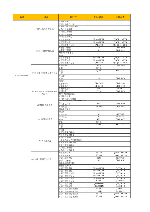
汽车底盘零部件常用金属材料手册-汇总
右前支架-后转向节安装位
左后支架-后转向节安装位
右后支架-后转向节安装位
调整支架-后下摆臂
左后下摆臂大轴套支架一
右后下摆臂大轴套支架一
左后下摆臂大轴套支架二
右后下摆臂大轴套支架二
套管-后下摆臂大轴套
套管-后下摆臂小轴套
防转支架
四方螺母
连杆球销
衬套
压盖
左/右后横向稳定杆连接杆总成 卡簧
防尘套
球销座
连杆
GB/T8162
GB/T699 GB/T3077
Q/ASB275
Q/BQB 403 GB/T699
GB/T 3077
Q235/ST12 GB/T699
GB/T699 GB/T3078 GB1348 GB1348 Q/ASB312 GB/T 9439
GB/T 699
GB/T3077
GB/T699 GB/T3077
后横向稳定杆左支架二 后横向稳定杆左/右支架总成
焊接方螺母 M8
后横向稳定杆右支架
后下摆臂大轴套端板
后下摆臂护板
左后下摆臂
右后下摆臂
左后下摆臂连接板
右后下摆臂连接板
后下摆臂小轴套连接板
连接板定位块
后下摆臂端板
左后下摆臂减震器支架
右后下摆臂减震器支架
左后稳定杆支架-下摆臂
左/右后下摆臂焊接总成
右后稳定杆支架-下摆臂 左前支架-后转向节安装位
Q/BQB310 Q/BQB310 Q/BQB310 Q/BQB310 Q/BQB310 Q/ASB275 Q/BQB310 Q/BQB310 Q/ASB275 Q/ASB275 Q/WG(RZ)02 Q/WG(RZ)02
后悬架与制动系统
汽车零部件说明书

保修及保养手册重要信息 (1)包修部分 (3)整车质量担保 (3)易损件质量担保 (6)保养部分 (8)保养目的 (8)保养计划 (9)车辆常规保养检修记录 (17)车辆非常规保养检修记录 (31)安全带预张紧器、安全气囊更换记录 (35)用户变更记录 (37)附件:上汽集团授权售后服务中心名单 (39)重要信息对您的建议我们建议您前往上汽集团授权售后服务中心保养和维修您的车辆。
因为只有上汽集团授权售后服务中心最了解您的汽车,并且在这里您可以得到上汽集团纯正的零部件和专业的技术。
我们的质量担保(车辆包修)也只有在上汽集团授权售后服务中心才能实现。
车辆的使用和注意事项我们的汽车使用了很多最先进的技术,因此请您在使用车辆前务必认真阅读《用户手册》,并遵从本手册和《用户手册》的要求进行保养和包修。
如果您对于如何使用、保养和包修本车存有疑问,请询问上汽集团授权售后服务中心。
请使用符合上汽集团技术规范和质量标准要求并适用本车的附件、零部件和车用油液,并按正确的操作程序保养和维修您的车辆,详情可咨询当地授权售后服务中心。
并请您尊重知识产权,使用正版的附件、零部件等,如果使用了侵犯知识产权的附件、零部件等,您将有可能承担相应的法律风险和法律后果。
免费更换发动机机油和机油滤清器服务上汽集团授权售后服务中心将为您提供一次免费的发动机机油和机油滤清器的更换服务,免费服务将包括材料和工时费用,免费服务的有效期同整车的包修期,免费更换服务只在上汽集团授权售后服务中心进行。
保养检修记录本手册中有两种保养检修记录表,分别记录“常规保养”和“非常规保养”的保养检修情况。
请务必保留保养检修记录表,它将为您和上汽集团授权售后服务中心提供分析失效原因的依据。
包修部分整车质量担保上汽集团将根据以下条款、条件和限制对整车提供包修服务。
除中国法律的强制性规定外,本手册规定了上汽集团对用户承担的包修责任。
■包修期上汽集团为新车提供了3年或10万公里(两者以先到达者为准)的包修期。
SCIEX备品备件及耗材手册 LC-MS MS实验室指南 2019版说明书

欢迎无论您使用的是SCIEX Triple Quad™、Qtrap®、TripleTof®、X500系列QTOF、毛细管电泳(CE)或ExionLC™系统,您需要的、保证您的仪器正常运行和高性能运转的零配件和其它供应品都在本手册中。
您将看到标记的是我们建议保留在手边的备品备件及耗材,以防止工作流程中断。
为什么需要SCIEX原厂零配件?只有SCIEX原装零件和供应品才能保证他们的工作性能与您的仪器随机附带的零件和供应品相同。
SCIEX原装部件由经过SCIEX认证的专业服务人员测试,并且具有原厂验证的高质量。
请记住,使用第三方零配件或二手零配件可能会影响您仪器系统的性能。
另外,SCIEX对原厂销售的零配件提供支持,因此您可以确信,您使用的零配件是合格的零配件。
如果零配件出现问题,我们会负责维修或更换原厂零配件。
为什么需要SCIEX原厂服务?根据最近的一项民意调查*,SCIEX服务在质谱供应商中的客户满意度排名为第一。
使SCIEX服务与众不同的是我们对SCIEX LC-MS和CE技术以及工作流程的密切关注。
这种深度知识和专业知识是任何第三方供应商都不可比拟的。
SCIEX服务是SCIEX Now™支持网络的一部分,它是一个集服务、技术支持和培训资源为一体的支持系统,能够帮助SCIEX用户比以往更快、更轻松地获得答案。
有关更多信息,请访问SCIEX. com/support。
*数据由Ohriner Research在2017年10月民意调查获得目录SCIEX TRIPLE QUAD AND QTRAP系统3200 Series (3)4000 Series (4)5000 Series (5)SCIEX TRIPLE QUAD AND QTRAP系统3500 Series (6)4500 Series (7)5500 Series (8)6500 Series (9)TRIPLETOF系列TripleTOF 4600 System (10)TripleTOF 5600/5600+ System (11)TripleTOF 6600 System. . . . . . . . . . . . . . . . . . . . . . . . . . . . . . . . . . . . . . . . . . . . . . . . . . . . . . . . . . . . . . . . . . . . . . . . . . . . 12 X500R QTOF System (13)X500B QTOF System (13)离子源TurboIonSpray® (14)Turbo V™ (15)IonDrive™. . . . . . . . . . . . . . . . . . . . . . . . . . . . . . . . . . . . . . . . . . . . . . . . . . . . . . . . . . . . . . . . . . . . . . . . . . . . . . . . . . . . . . . . 15 DuoSpray Ion (16)Turbo V (X500) . . . . . . . . . . . . . . . . . . . . . . . . . . . . . . . . . . . . . . . . . . . . . . . . . . . . . . . . . . . . . . . . . . . . . . . . . . . . . . . . . . . 16液相和毛细管电泳系统ExionLC™ AD. . . . . . . . . . . . . . . . . . . . . . . . . . . . . . . . . . . . . . . . . . . . . . . . . . . . . . . . . . . . . . . . . . . . . . . . . . . . . . . . . . . . . 17 ExionLC™ AC (17)ExionLC™ 100. . . . . . . . . . . . . . . . . . . . . . . . . . . . . . . . . . . . . . . . . . . . . . . . . . . . . . . . . . . . . . . . . . . . . . . . . . . . . . . . . . . . 18 Eksigent HPLC Systems . . . . . . . . . . . . . . . . . . . . . . . . . . . . . . . . . . . . . . . . . . . . . . . . . . . . . . . . . . . . . . . . . . . . . . . . . . . 18 SCIEX Capillary Electrophoresis Systems CESI 8000 Plus/PA800 Plus/MDQ Plus/GeXP (19)Phenomenex SecurityLINK and SecurityCAP . . . . . . . . . . . . . . . . . . . . . . . . . . . . . . . . . . . . . . . . . . . . . . . . . . . . . . . . 20 - 代表关键产品,SCIEX建议保留在手边的零配件和供应品,以防止工作流程中断注意:SCIEX建议所有零配件由专业人员安装。
长城汽车赛铃、赛酷系列零部件手册说明书
每天进步一点点
PDF 文件使用 "pdfFactory" 试用版本创建 肀ww肀
3. This manual provides the components (maintenance fittings)code of the surface color of the internal
series parts and components (maintenance fittings) with updated, modificated and added new content.
The Usage of this manual:
1. Provide most of the SAILOR、SOCOOL users with references, when users need to know item code, name, quantity and
前言
本着精简、高效、实用、统一、参考的原则,在较短的时间内完成了《长城汽车赛铃、赛酷系列零部件手册(维 修配件)》第三版。它是在第二版《长城汽车赛铃、赛酷系列零部件手册(维修配件)》基础上更新、改进、补充部分内容后编制 而成的最新版本。
这本手册的用途是: 1 . 可供广大赛铃、赛酷皮卡汽车用户了解赛铃、赛酷系列轻型货车各种车型的零部件代号、名称、用量、适用车型、 零部件之间的装配关系及其结构组成时参考。 2 . 可供广大用户、维修站(点)选择和购买赛铃、赛酷系列轻型货车各车型的零部件和维修配件时参考。 3 . 可供企业内部、长城售后服务公司、配件部及市场服务工作的相关人员为用户和维修站(点)进行售后服务工作时 参考。
This manual is edited according to the technologic information of SAILOR、SOCOOL automobiles produced by our company now. With the increasingly development of technology, the structure of the SAILOR、SOCOOL automobiles will be
汽车零部件质量控制手册

汽车零部件质量控制手册第1章质量控制体系概述 (4)1.1 质量管理体系 (4)1.1.1 质量管理体系的概念 (4)1.1.2 质量管理体系的标准 (4)1.1.3 质量管理体系文件的构成 (4)1.2 质量控制流程 (4)1.2.1 设计与开发控制 (4)1.2.2 供应商管理 (4)1.2.3 生产过程控制 (4)1.2.4 检验与测试 (4)1.2.5 不良品控制 (5)1.2.6 顾客满意度管理 (5)1.3 质量控制组织结构 (5)1.3.1 质量管理部门 (5)1.3.2 质量管理团队 (5)1.3.3 质量改进小组 (5)1.3.4 员工培训与激励 (5)第2章零部件供应商管理 (5)2.1 供应商评审 (5)2.1.1 评审标准 (5)2.1.2 评审流程 (6)2.2 供应商质量控制 (6)2.2.1 质量控制体系 (6)2.2.2 质量控制措施 (6)2.3 供应商评价与激励 (6)2.3.1 评价体系 (6)2.3.2 激励机制 (7)第3章设计质量控制 (7)3.1 设计输入质量控制 (7)3.1.1 设计输入要求 (7)3.1.2 设计输入评审 (7)3.1.3 设计输入验证 (7)3.2 设计过程质量控制 (7)3.2.1 设计策划 (7)3.2.2 设计评审 (8)3.2.3 设计变更控制 (8)3.3 设计输出质量控制 (8)3.3.1 设计输出要求 (8)3.3.2 设计输出验证 (8)3.3.3 设计输出评审 (8)第4章材料质量控制 (9)4.1.1 原材料采购控制 (9)4.1.2 原材料验收标准 (9)4.1.3 原材料存储管理 (9)4.1.4 原材料变质处理 (9)4.2 辅助材料质量控制 (9)4.2.1 辅助材料采购与验收 (9)4.2.2 辅助材料存储管理 (9)4.2.3 辅助材料变质处理 (9)4.3 材料检验与试验 (10)4.3.1 检验与试验计划 (10)4.3.2 检验与试验方法 (10)4.3.3 检验与试验设备 (10)4.3.4 检验与试验结果处理 (10)4.3.5 检验与试验人员培训 (10)第5章制造过程质量控制 (10)5.1 工艺规划与管理 (10)5.1.1 工艺流程设计 (10)5.1.2 工艺参数确定 (10)5.1.3 工艺文件编制 (10)5.1.4 工艺改进与优化 (11)5.2 制造过程监控 (11)5.2.1 在线检测 (11)5.2.2 抽样检验 (11)5.2.3 制程能力分析 (11)5.2.4 质量追溯 (11)5.3 关键工序质量控制 (11)5.3.1 关键工序识别 (11)5.3.2 作业人员培训 (11)5.3.3 设备维护与管理 (11)5.3.4 质量控制点设置 (11)5.3.5 质量数据分析 (12)第6章质量检验与测试 (12)6.1 检验计划与实施 (12)6.1.1 检验计划制定 (12)6.1.2 检验计划实施 (12)6.2 检验方法与手段 (12)6.2.1 外观检验 (12)6.2.2 尺寸检验 (12)6.2.3 功能性检验 (12)6.2.4 无损检测 (12)6.3 测试设备与试验 (12)6.3.1 设备要求 (12)6.3.2 常用测试设备 (13)6.3.4 试验结果判定 (13)第7章质量改进 (13)7.1 质量问题识别与分析 (13)7.1.1 质量问题识别 (13)7.1.2 质量问题分析 (13)7.2 质量改进措施 (14)7.2.1 制定改进计划 (14)7.2.2 实施改进措施 (14)7.3 质量改进效果评估 (14)7.3.1 评估方法 (14)7.3.2 评估结果应用 (14)第8章错误预防与风险管理 (14)8.1 错误预防机制 (14)8.1.1 设计阶段错误预防 (14)8.1.2 制造过程错误预防 (15)8.1.3 供应链管理错误预防 (15)8.2 风险识别与评估 (15)8.2.1 风险识别 (15)8.2.2 风险评估 (15)8.3 风险控制与应对 (15)8.3.1 风险控制 (15)8.3.2 风险应对 (15)8.3.3 风险沟通 (15)第9章售后服务与客户满意度 (15)9.1 售后服务政策 (15)9.1.1 目的 (15)9.1.2 范围 (16)9.1.3 服务内容 (16)9.1.4 服务承诺 (16)9.2 客户投诉处理 (16)9.2.1 投诉渠道 (16)9.2.2 投诉处理流程 (16)9.2.3 投诉处理时限 (16)9.3 客户满意度调查与改进 (16)9.3.1 调查方法 (16)9.3.2 调查内容 (16)9.3.3 改进措施 (17)第10章质量培训与持续发展 (17)10.1 质量意识培训 (17)10.1.1 培训目的 (17)10.1.2 培训内容 (17)10.1.3 培训方式 (17)10.2 质量管理技能培训 (17)10.2.2 培训内容 (17)10.2.3 培训方式 (18)10.3 持续改进与发展计划 (18)10.3.1 改进目标 (18)10.3.2 改进措施 (18)10.3.3 发展计划 (18)第1章质量控制体系概述1.1 质量管理体系1.1.1 质量管理体系的概念质量管理体系是指在汽车零部件企业内部,为实现产品质量目标,按照一定的质量管理原则和方法,建立起来的一套系统的质量管理和质量保证活动体系。
汽车零部件质量管理手册

汽车零部件质量管理手册第一章概述 (3)1.1 汽车零部件质量管理的重要性 (3)1.1.1 保障汽车安全 (3)1.1.2 提升汽车功能 (3)1.1.3 延长汽车使用寿命 (3)1.1.4 降低维修成本 (3)1.2 质量管理体系标准及要求 (4)1.2.1 ISO 9001质量管理体系 (4)1.2.2 ISO/TS 16949汽车行业质量管理体系 (4)1.2.3 美国质量管理体系标准(QS9000) (4)1.2.4 中国质量管理体系标准(GB/T 19001) (4)1.2.5 质量策划 (4)1.2.6 过程控制 (4)1.2.7 持续改进 (4)1.2.8 人力资源管理 (4)第二章质量策划 (5)2.1 质量目标制定 (5)2.2 质量计划编制 (5)2.3 质量风险管理 (6)第三章设计开发 (6)3.1 设计输入与输出 (6)3.2 设计评审 (7)3.3 设计验证与确认 (7)第四章采购管理 (8)4.1 供应商选择与评价 (8)4.1.1 供应商选择原则 (8)4.1.2 供应商评价方法 (8)4.2 采购过程控制 (8)4.2.1 采购计划管理 (9)4.2.2 采购合同管理 (9)4.2.3 采购质量控制 (9)4.3 供应商质量提升 (9)4.3.1 供应商质量培训 (9)4.3.2 供应商质量改进 (9)4.3.3 供应商激励机制 (9)第五章生产过程控制 (9)5.1 生产作业指导 (9)5.2 生产过程监控 (10)5.3 不合格品控制 (10)第六章质量检验 (11)6.1 检验标准与方法 (11)6.1.1 检验标准 (11)6.1.2 检验方法 (11)6.2 检验计划与实施 (11)6.2.1 检验计划 (11)6.2.2 检验实施 (12)6.3 检验结果处理 (12)6.3.1 不合格品处理 (12)6.3.2 检验记录与分析 (12)6.3.3 持续改进 (12)第七章质量改进 (12)7.1 质量改进工具与方法 (12)7.2 质量改进计划与实施 (13)7.3 持续改进 (13)第八章质量成本控制 (14)8.1 质量成本分析 (14)8.2 质量成本管理 (14)8.3 质量成本优化 (15)第九章客户服务与满意度 (15)9.1 客户服务政策 (15)9.1.1 以客户为中心 (15)9.1.2 服务标准化 (16)9.1.3 服务承诺 (16)9.1.4 服务监督与改进 (16)9.2 客户满意度调查与评价 (16)9.2.1 满意度调查方法 (16)9.2.2 满意度评价指标 (16)9.2.3 满意度调查频率 (16)9.3 客户投诉处理 (16)9.3.1 投诉接收 (16)9.3.2 投诉处理流程 (17)9.3.3 投诉处理时效 (17)9.3.4 投诉统计分析 (17)第十章内部审核与外部审核 (17)10.1 审核目的与范围 (17)10.1.1 审核目的 (17)10.1.2 审核范围 (17)10.2 审核实施与报告 (17)10.2.1 审核实施 (18)10.2.2 审核报告 (18)10.3 审核后续整改 (18)10.3.1 整改措施 (18)10.3.2 整改跟踪 (18)10.3.3 持续改进 (18)第十一章管理评审 (18)11.1 管理评审的目的与要求 (18)11.1.1 目的 (18)11.1.2 要求 (19)11.2 管理评审的实施与记录 (19)11.2.1 实施步骤 (19)11.2.2 记录 (19)11.3 管理评审的整改措施 (19)11.3.1 整改措施的分类 (19)11.3.2 整改措施的实施 (20)第十二章人力资源与培训 (20)12.1 人力资源规划与管理 (20)12.2 员工培训与发展 (20)12.3 质量意识提升与激励 (21)第一章概述1.1 汽车零部件质量管理的重要性汽车零部件作为汽车制造的核心组成部分,其质量直接关系到整车的功能、安全及使用寿命。
- 1、下载文档前请自行甄别文档内容的完整性,平台不提供额外的编辑、内容补充、找答案等附加服务。
- 2、"仅部分预览"的文档,不可在线预览部分如存在完整性等问题,可反馈申请退款(可完整预览的文档不适用该条件!)。
- 3、如文档侵犯您的权益,请联系客服反馈,我们会尽快为您处理(人工客服工作时间:9:00-18:30)。
型号80S
MODEL 80S系列高压空气压缩机
80S SERIES HIGH PRESSURE AIR COMPRESSOR
零部件手册
PARTS LIST
南京尚爱机电有限公司
NANJING SHANGAIR MECHANICAL & ELECTRICAL CO., LTD.
SMS80-01-1008
目录
图A:80S单机组外形图、明细表……………..……………………..…….2 页图B:80S主机外形图、明细表…………………………..……..……….…4 页图1:曲轴箱部件、明细表.….…….…………..……..……………….……5 页图2:一级气缸活塞连杆部件……………………………….……….……..7 页图3:二级气缸活塞连杆部件…………………..……..…….……..……...10 页图4:三级气缸活塞连杆部件…………………..……..…….…………….13 页图5:四级气缸活塞连杆部件…………………..……..…….…………….15 页图6:中间冷却器………………….………………..……..…….…………17 页图7:80S单机组电路图.………………..……..……...……..……………..18 页表8:80S机头全套密封垫明细表……………..……..….…...……..……..19 页
图A:单机组80S外形图
单机组80S
图B:机头80S外形图
图1:曲轴箱部件 1套
曲轴箱部件 1套
序号图号名称数量备注1-01 螺栓M10*30-8.8级GB 12
1-02 紫铜平垫圈10 GB 12
1-03 JT.04.00.12 内六角放油螺塞ZG1/2" 1
1-04 O型圈25*3.55 O型圈 1
1-05 YB.01.00.00 油标M27*1.5 1
1-06 O型圈23.5*3.55 O型圈 1
1-07 09.01.00.06 加油口盖 1
1-08 80.00.00.01 曲轴箱盖 1
1-09 80.00.00.02 曲轴箱盖纸垫 1
1-10 80.00.03.A4 曲轴箱总成 1
1-11 11.01.00.06 轴承端盖纸垫 1
1-12 11.01.00.A5 轴承端盖 1
1-13 唇形密封圈FB55*75*12 密封圈 2 常备1-14 紫铜平垫圈10 垫圈 4
1-15 螺栓M10*30-8.8级螺栓 4
1-16 80.00.00.05 风扇轮 1
1-17 螺母M39*2 螺母 1
图2:一级气缸活塞连杆部件 1套一级气缸活塞连杆部件 1套
图3:二级气缸活塞连杆部件 1套二级气缸活塞连杆部件 1套
图4:三级气缸活塞连杆部件 1套三级气缸活塞连杆部件 1套
图5:四级气缸连杆活塞部件四级气缸活塞连杆部件 1套
图6:中间冷却器
图7:单机组电路图表8:80S全套密封垫明细表
(是上述密封垫片的汇总)。