你清楚没有USB-C-to-USB-C-E-marker-5A数据线
USB Type-C ECN for Vconn Requirements

Title: USB Type-C ECR Vconn RequirementsApplied to: USB Type-C Specification Release 1.2, March 25, 2016Actual Change(a). Section 4.4.3 V CONNFrom Text:V CONN is provided by the DFP to power cables with electronics in the plug. V CONN is provided over the CC pin that is determined not to be connected to the CC wire of the cable.Initially, V CONN shall be sourced on all DFP USB Type-C receptacles that utilize the SSTX and SSRX pins during specific connection states as described in Section 4.5.2.2. Subsequently, V CONN may be removed under some circumstances as described in Table 4-3. V CONN may also be sourced by USB Type-C receptacles that do not utilize the SSTX and SSRX pins as described in Section 4.5.2.2. USB PDV CONN_Swap command also provides the DFP a means to request that the attached UFP source V CONNTable 4-4 provides the voltage and power requirements that shall be met for V CONN. See Section 4.9 for more details about Electronically Marked Cables. See Section 4.10 for a wider V CONN voltage operating range for V CONN-powered accessories. See Section 5.1 regarding optional support for an increased V CONN power range in Alternate Modes.Table 4-4 V CONN Source CharacteristicsTo aid in reducing the power associated with supplying Vconn, a Source is allowed to either not sourc Vconn or turn off Vconn under any of the following conditions:∙Ra is not detected on the CC pin after tCCDebounce when the other CC pin is in the SRC.Rd state∙Ra is not detected on the CC pin after the tCCDebounce when the other CC pin is in the SRC.Open state and supports Vconn-powered accessories.∙If there is no GoodCRC response to USB PD Discover Identity messagesTable 4-5 provides the requirements that shall be met for cables that consume V CONN power.Table 4-5 V CONN Sink CharacteristicsThe cable may remove or weaken Ra when V CONN is above 1.0 V as long as the other requirements are met. See Section 4.5.1.2.1.To Text:V CONN is provided by the DFP to power cables with electronics in the plug. V CONN is provided over the CC pin that is determined not to be connected to the CC wire of the cable.Initially, V CONN shall be sourced on all DFP USB Type-C receptacles that utilize the SSTX and SSRX pins during specific connection states as described in Section 4.5.2.2. Subsequently, V CONN may be removed under some circumstances as described in Table 4-3. V CONN may also be sourced by USB Type-C receptacles that do not utilize the SSTX and SSRX pins as described in Section B PDV CONN_Swap command also provides the DFP a means to request that the attached UFP source V CONN ArrayTable 4-4 provides the voltage and power requirements that shall be met for V CONN. See Section 4.9 for more details about Electronically Marked Cables. See Section 5.1 regarding optional support for an increased V CONN power range in Alternate Modes.Table 4-4 V CONN Source CharacteristicsTo aid in reducing the power associated with supplying V CONN, a Source is allowed to either not source V CONN or turn off V CONN under any of the following conditions:∙Ra is not detected on the CC pin after tCCDebounce when the other CC pin is in the SRC.Rd state∙Ra is not detected on the CC pin after the tCCDebounce when the other CC pin is in the SRC.Open state and supports Vconn-powered accessories∙If there is no GoodCRC response to USB PD Discover Identity messagesTable 4-5 provides the requirements that shall be met for cables that consume V CONN power.Table 4-5 Cable V CONN Sink CharacteristicsThe cable shall remove or weaken Ra when V CONN is in the valid voltage range. The cable shall reapply Ra when V CONN falls below vRaReconnect as defined in Table 4-5. The cable shall discharge V CONN to below vV CONN Discharge on a cable disconnect. The cable shall take into account the V CONNcapacitance present in the cable when discharging V CONN.Implementation Note: Increasing Ra to 20KOhm will meet both the power dissipation for Electronically Marked Passive Cables and discharge 10uF to less than vV CONN Discharge intV CONN Discharge.The maximum power consumption while in an Alternate Mode is defined by the Alternate Mode.Table 4-6 V CONN Powered Accessory Sink CharacteristicsThe V CONN powered accessory shall remove or weaken Ra when V CONN is in the valid voltage range. The V CONN powered accessory shall reapply Ra when V CONN falls below vRaReconnect as defined in Table 4-6. The V CONN powered accessory shall take into account the V CONN capacitance present in the accessory when discharging V CONN.The maximum power consumption while in an Alternate Mode is defined by the Alternate Mode.(b). Add new Cable State Machine Requirements SectionNew Text and Figures:4.5.2.4 Cable State Machine RequirementsFigure 4-18 illustrates the passive cable Electronic Marker connection state diagram. Figure 4-19 illustrates the active cable Electronic Marker connection state diagram.Figure 4-18 Passive Cable Electronic Marker State DiagramFigure 4-19 Active Cable Electronic Marker State Diagram4.5.2.4.1 Cable Power On StateThis state appears in Figure 4-18 and Figure 19. This is the initial power on state for the Electronic Marker in the cable when V CONN is applied.4.5.2.4.1.2 Cable Power On State RequirementsThe Electronic Marker in the cable shall present Ra when no V CONN is applied.The Electronic Marker in the cable shall power on may continue to present Ra in this state.The cable shall not respond to SOP’ and SOP” commands in this state.4.5.2.4.1.3 Exiting from Cable Power On StateThe Electronic Marker in a passive cable shall transition to Assign SOP’ when it has completed its boot process. The Electronic Marker in the passive cable shall transition to Assign SOP’ withintV CONN Stable, Table 5-4.The Electronic Marker in an active cable shall transition to Unassigned SOP when it has completed its boot process. The Electronic Marker in the active cable shall transition to Unassigned SOP within tV CONN Stable, Table 5-4.4.5.2.4.2 Unassigned SOP StateThis state appears in Figure 4-19. The Electronic Marker in the active cable can detect the voltage on V CONN in this state and is waiting to assign SOP’ and SOP” if supported.4.5.2.4.2.1 Unassigned SOP State RequirementsThe Electronic Marker in the active cable shall not respond to any USB PD communication sent to SOP’ or SOP” while in this state.The cable shall weaken or remove Ra if it has not already done so.The Active cable shall meet the Power for Active Cables defined in Table 4-5.The Electronic Marker in the active cable shall detect V CONN on the local cable plug or on the remote cable plug.4.5.2.4.2.3 Exiting from Unassigned SOP StateThe Electronic Marker in the active cable shall transition to Assign SOP’ when it detects V CONN present on its local cable plug and no V CONN being received from the remote cable plug.The Electronic Marker in the active cable shall transition to Assign SOP” when it detects V CONN being received from the remote cable plug and it does not detect V CONN from its local cable plug. The Electronic Marker in the active cable may stay in Unassigned SOP if it does not supports SOP”.The Electronic Marker in the active cable should remain in Unassigned SOP if it detects V CONN present on the local cable plug and the remote cable plug at the same time.4.5.2.4.3 Assign SOP’ StateThis state appears in Figure 4-18 and Figure 4-19. The cable Electronic Marker responds to SOP’ in this state.4.5.2.4.3.1 Assign SOP’ State RequirementsThe Electronic Marker in the passive or active cable shall be able to respond to any USB PD communication sent to SOP’.The Electronic Marker in the passive cable shall weaken or remove Ra if it has not already done so.Passive cables shall meet the Power for Electronically Marked Passive Cables defined in Table 4-5.Active Cables shall meet the Power for Active cables in Table 4-5.4.5.2.4.3.2 Exiting from Assign SOP’ StateThe Electronic Marker in the passive or active cable shall transition to Cable Power On upon sensing V CONN less than vRaReconnect defined in Table 4-5 or upon a Power On Reset event.The Electronic Marker in the passive cable shall transition to Cable Power On upon sensing a Hard Reset or Cable Reset.The Electronic Marker in the active cable shall transition to Unassigned SOP upon sensing a Hard Reset or Cable Reset.4.5.2.4.4 Assign SOP” State (Optional Normative)This state appears in Figure 4-19. The active cable Electronic Marker responds to SOP” in this state. This state is not required to be supported by an active cable.4.5.2.4.4.1 Assign SOP” State RequirementsThe Electronic Marker in the active cable shall be able to respond to any U SB PD communication sent to SOP”.The Electronic Marker shall weaken or remove Ra to meet the maximum power defined in Table 4-5 if it has not already done so.4.5.2.4.4.2 Exiting from Assign SOP” StateThe Electronic Marker in the active cable shall transition to Cable Power On upon sensing Vconn less than vRaReconnect defined in Table 4-5 or on a Power On Reset event.The Electronic Marker in the active cable shall transition to Unassigned SOP upon sensing a Hard Reset or Cable Reset.(c). Section 4.6.1.2 V CONN Requirements during USB Suspend, Page168From Text:4.6.1.2 VCONN Requirements during USB SuspendIf the Source supplies V BUS power during USB suspend, it shall also supply at least 7.5 mA to V CONN. Electronically marked cables shall draw no more than 7.5 mA from V CONN during USB suspend.To Text:4.6.1.2 VCONN Requirements during USB SuspendIf the Source supplies V BUS power during USB suspend, it shall also supply V CONN and meet the requirements defined in Table 4-4.Electronically marked cables shall meet the requirements in Table 4-5 during USB suspend.V CONN powered accessories shall meet the requirements defined in Table 4-6 during USB suspend.(d). Section 4.10 V CONN– Powered Accessories, Page 176From Text:A V CONN-powered accessory is a direct-attach Sink that implements an Alternate Mode (See Section5.1) and can operate with just V CONN.The V CONN-powered accessory exposes a maximum impedance to ground of Ra on the V CONN pin and Rd on the CC pin.When operating in the UFP role and when V BUS is not present, V CONN-powered accessories shall treat the application of V CONN as an attach signal, and shall respond to USB Power Delivery messages.When powered by only V CONN, a V CONN-powered accessory shall negotiate an Alternate Mode. If it fails to negotiate an Alternate Mode within tAMETimeout, its port partner removes V CONN.V CONN-powered accessories shall be able to operate over a range of 2.7 V to 5.5 V on V CONN.The removal of V CONN when V BUS is not present shall be treated as a detach event.When V BUS is supplied, a V CONN-powered accessory is subject to all of the requirements for Alternate Modes, including presenting a USB Billboard Device Class interface if negotiation for an Alternate Mode fails.To Text:A V CONN-powered accessory is a direct-attach Sink that implements an Alternate Mode (See Section5.1) and can operate with just V CONN.The V CONN-powered accessory exposes a maximum impedance to ground of Ra on the V CONN pin and Rd on the CC pin.When operating in the Sink role and when V BUS is not present, V CONN-powered accessories shall treat the application of V CONN as an attach signal, and shall respond to USB Power Delivery messages. When powered by only V CONN, a V CONN-powered accessory shall negotiate an Alternate Mode. If it fails to negotiate an Alternate Mode within tAMETimeout, its port partner removes V CONN.V CONN-powered accessories shall comply with Table 4-6.The removal of V CONN when V BUS is not present shall be treated as a detach event.When V BUS is supplied, a V CONN-powered accessory is subject to all of the requirements for Alternate Modes, including presenting a USB Billboard Device Class interface if negotiation for an Alternate Mode fails.(e). Section 4.9 Electronically Marked Cables, Pages 175 - 176From Text:4.9 Electronically Marked CablesAll USB Full-Featured Type-C cables shall be electronically marked. USB 2.0 Type-C cables may be electronically marked.Electronically marked cables shall support USB Power Delivery Structured VDM Discover Identity command d irected to SOP’. This provides a method to determine the characteristics of the cable, e.g. its current carrying capability, its performance, vendor identification, etc. This may be referred to as the USB Type-C Cable ID function.Prior to an explicit USB PD contract, a Sourcing Device is allowed to use SOP’ to discover the cable’s identity. After an explicit USB PD contract has been negotiated, only the Source shall communicate with SOP’ and SOP” (see Section 5.2.2).An electronically marked cable incorporates electronics that require V CONN, although V BUS or another source may be used. Electronically marked cables that do not incorporate data bus signal conditioning circuits shall consume no more than 70 mW from V CONN. During USB suspend, electronically marked cables shall not draw more than 7.5 mA from V CONN, see Section 4.6.1.2.Figure 4-37 illustrates a typical electronically marked cable. The isolation elements (Iso) shall prevent V CONN from traversing end-to-end through the cable. Ra is required in the cable to allow the Source to determine that V CONN is needed.Figure 4-38 illustrates an electronically marked cable where the V CONN wire does not extend through the cable, therefore an SOP’ element is required at each end of the cable. In this case, no isolation elements are needed.For cables that only respond to SOP’, the location of the responder is not relevant.An active cable is an electronically marked cable that incorporates data bus signal conditioning circuits, for example to allow for implementing longer cables. Active cables shall not draw more than 1 W from V CONN, see Section 4.4.3.Active cables may or may not require configuration management. Requirements for active cables that require configuration management are provided in Section 5.2.Refer to Section 4.4.3 for the requirements of a Source to supply V CONN. When V CONN is not present, a powered cable shall not interfere with normal CC operation including Sink detection, current advertisement and USB PD operation.To Text:4.9 Electronically Marked CablesAll USB Full-Featured Type-C cables shall be electronically marked. USB 2.0 Type-C cables may be electronically marked.Electronically marked cables shall support USB Power Delivery Structured VDM Discover Identity command directed to SOP’. This provides a method to determine the characteristics of the cable, e.g. its current carrying capability, its performance, vendor identification, etc. This may be referred to as the USB Type-C Cable ID function.Prior to an explicit USB PD contract, a Sourcing Device is allowed to use SOP’ to discover the cable’s identity. After an explicit USB PD contract has been negotiated, only the Source shall communicate with SOP’ and SOP” (see Section 5.2.2).Electronically marked passive cables shall follow the Cable State Machine defined in 4.5.2.4 and Figure 4-18.An E lectronically marked cable s incorporates electronics that require are generally powered fromV CONN, although V BUS or another source may be used.Electronically marked cables that do not incorporate data bus signal conditioning circuits shall consume no more than 70 mW from V CONN.shall meetthe maximum power defined in Table 4-5. During USB suspend, electronically marked cables shall not draw more than 7.5 mA from V CONN, see Section 4.6.1.2.Refer to Table 4-4 for the requirements of a Source to supply V CONN. When V CONN is not present, a powered cable shall not interfere with normal CC operation including Sink detection, current advertisement and USB PD operation.Figure 4-37 illustrates a typical electronically marked cable. The isolation elements (Iso) shall prevent V CONN from traversing end-to-end through the cable. Ra is required in the cable to allow the Source to determine that V CONN is needed.Figure 4-38 illustrates an electronically marked cable where the V CONN wire does not extend through the cable, therefore an SOP’ element is required at each end of the cable. In this case, no isolation elements are needed.For cables that only respond to SOP’, the location of the responder is not relevant.4.9.1 Parameter ValuesTable 4-15 provides the power on timing requirements for SOP’ and SOP” to be ready to communicate.Table 4-15 SOP’ and SOP” Timing4.9.2 Active CablesAn active cable is an electronically marked cable that incorporates data bus signal conditioning circuits, for example to allow for implementing longer cables. Active cables with data bus signal conditioning in both plugs shall implement SOP’ and may implement SOP”. Active cables shall not draw more than 1 W from V CONN, see Section 4.4.3. meet the power requirements defined in Table 4-5.Active cables may support either one SSTX/SSRX pair or two SSTX/SSRX pairs. The Electronic Marker in the cable shall identify the number of SSTX/SSRX lanes supported.Active cables may or may not require configuration management for alternate modes. Requirements for a Active cable s that require configuration management is defined are provided in Section 5.2.(f). Section 5.2 Managed Active Cables, Pages 190 - 192From Text:5.2 Managed Active CablesActive cables that require configuration (managed active cable) shall use USB Power Delivery StructuredVDMs to discover and configure the cable.USB Power Delivery Structured VDMs provide a standardized mechanism for identifying and managing thefunctionality of active cables.Some managed active cables only have a single USB PD controller in the cable that responds to USB PDStructured VDMs sent to SOP’.When a managed active cable requires independent management at each end of the cable, separate USB PD controllers responding to USB PD Structured VDMs sent to SOP’ and SOP” can be located in each plug.5.2.1 Requirements for Managed Active Cables that respond to SOP’ and SOP”After a power-on reset event or a USB PD Hard Reset, the USB PD controller attached to the Source is assignedSOP’ and the USB PD controller attached to the Sink is assigned SOP”. After a USB PD Cable Reset, the plug being supplied V CONN responds to SOP’ independent of whether it is the plug atta ched to the Source or Sink.The controllers can sense whether they are SOP’ or SOP” based on the presence of V CONN at the plug’s V CONNpin as only one port supplies V CONN.Figure 5-6 illustrates the process that shall be followed to assign SOP’ and SOP” to the ends attached to theSource and Sink, respectively, at power on. In the Unassigned state, the active cable will not respond to any USB PD communication sent to SOP’ or SOP”. The parameter tV CONN Stable allows time for the active cable to set up to communicate.When V CONN is removed, the plug’s local V CONN shall discharge to below its SOP’ detection threshold within 20 ms.A managed active cable shall assure that the two USB PD controllers are uniquely assigned via the mechanism described here, one as SOP’ and the other as SOP”.USB PD supports three types of USB Type-C-related swaps that may or may not impact V CONN:• USB PD V CONN_Swap – The port previously not supplying V CONN sources V CONN and the assignment of SOP’ and SOP” remain unchanged.• USB PD DR_Swap –The assignment of SOP’ and SOP” remain unchanged.• USB PD PR_Swap –The assignment of SOP’ and SOP” remain unchanged.Managed active USB Type-C to USB Type-C cables shall by default support USB operation. Multi-modal cables (e.g., an active cable that supports an Alternate Mode in addition to USB SuperSpeed) that use the TX/RX signal pairs shall minimally support USB 3.1Gen 1 operation. They are encouraged to support both Gen 1 and Gen 2 operation.Figure 5-7 illustrates a typical managed active cable. The isolation elements (Iso) shall prevent V CONN from traversing end-to-end through the cable. Ra is required in the cable to allow the DFP to determine that V CONN is needed.5.2.1.1 Parameter ValuesTable 5-2 provides the power on timing requirements for SOP’ and SOP” to be ready to communicate.Table 5-4 SOP’ and SOP” Timing5.2.2 Cable Message StructureUSB PD Structured VDMs shall be used to identify and manage active cables. Cables that require additionalfunctionality, for example to program parameters in the active electronics, may define proprietary Structured VDMs to provide the necessary functionality. In all cases, these messages shall only use SOP’ and SOP”. Theyshall not use SOP.SOP’ and SOP” are defined to allow a vendor to communicate individually with each end the cable.For active cables that support both SOP’ and SOP”, after attach or a USB PD Cable Reset, the plug directlyconnected to the Source shall only respond to SOP’ and the plug directly connected to the Sink shall only respond to SOP”.The assignment of SOP’ and SOP” to each plug remains persistent until V CONN is removed or a subsequent USB PD Cable Reset.The Discover Identity message shall start with SOP’.To Text:5.2 Managed Active CablesManaged active cables may have a single USB PD controller in the cable that responds to USB PD Structured VDMs sent to SOP’ if independent management of each end is not required.All managed active cables shall identify if they respond to SOP’ only or to both SOP’ and SOP” using the Discover Identity command defined in USB Power Delivery.5.2.1 Requirements for Managed Active Cables that respond to SOP’ and SOP”Managed active cables shall implement the Cable State Machine defined in 4.5.2.4 and Figure 4-19.A managed active cable which supports two USB PD controllers shall ensure the cable plugs are uniquely assigned via the mechanism described here, one as SOP’ and the other as SOP”.USB PD supports three types of USB Type-C-related swaps that may or may not impact V CONN:• USB PD V CONN_Swap – The port previously not supplying V CONN sources V CONN and the assignment of SOP’ and SOP” remain unchanged.• USB PD DR_Swap –The assignment of SOP’ and SOP” remain unchanged.• USB PD PR_Swap –The assignment of SOP’ and SOP” remain unchanged.Managed active USB Type-C to USB Type-C cables shall by default support USB operation. Modal cables (e.g., an active cable that supports an Alternate Mode in addition to USB SuperSpeed) that use the TX/RX signal pairs shall minimally support USB 3.1Gen 1 operation and are encouraged to support both Gen 1 and Gen 2 operation.Figure 5-7 illustrates a typical managed active cable. The isolation elements (Iso) shall prevent V CONN from traversing end-to-end through the cable. Ra must be present when no V CONN is applied to allow the DFP to determine that V CONN is needed.5.2.2 Cable Message StructureUSB PD Structured VDMs shall be used to identify and manage active cables. Cables that require additional functionality, for example to program parameters in the active electronics, may define proprietary Structured VDMs to provide the necessary functionality. In all cases, these messages shall only use SOP’ and SOP”. They shall not use SOP.SOP’ and SOP” are defined to allow a vendor to communicate individually with each cable end.The Discover Identity message shall start with SOP’.Source Sink。
新大陆1500扫描枪设置说明书

(NLS-HR15XX-3E)
手持式条码扫描器
用户手册
免责声明
请您在使用本手册描述的产品前仔细阅读手册的所有内容,以保障产品的安全有效地使用。阅读后请将本手册妥善保存以备下次 使用时查询。 请勿自行拆卸终端或撕毁终端上的封标,否则福建新大陆自动识别技术有限公司不承担保修或更换终端的责任。 本手册中的图片仅供参考,如有个别图片与实际产品不符,请以实际产品为准。对于本产品的改良更新,新大陆自动识别技术有 限公司保留随时修改文档而不另行通知的权利。 本手册包含的所有信息受版权的保护,福建新大陆自动识别技术有限公司保留所有权利,未经书面许可,任何单位及个人不得以 任何方式或理由对本文档全部或部分内容进行任何形式的摘抄、复制或与其它产品捆绑使用、销售。 本手册中描述的产品中可能包括福建新大陆自动识别技术有限公司或第三方享有版权的软件,除非获得相关权利人的许可,否则 任何单位或者个人不能以任何形式对前述软件进行复制、分发、修改、摘录、反编译、反汇编、解密、反向工程、出租、转让、 分许可以及其它侵犯软件版权的行为。 福建新大陆自动识别技术有限公司对本声明拥有最终解释权。
目
录
版本记录 ......................................................................................................................................................................................................- 3 前言 .........................................................................
pd协议最新版本

pd协议最新版本USB PD(Power Deliver)协议是USB IF协会制定的USB充电标准与技术,是目前主流的快充协议之一,其最大供电能力可达100W,被应用在各种设备的电源上。
USB PD协议利用USB Type-C接口的CC(Configuration channel)引脚作为数据传输通道来协商充电的电压、电流和功率传输方向,在介绍USB PD协议的具体内容之前,先简单介绍一下其依赖的USB Type-C接口。
如上图所示,Type-C接口可以完全替代Type-A、Type-B、Micro AB等各种USB接口,实现数据传输、电力传输。
USB PD协议就是基于Type-C接口的强大功能实现的。
Type-C接口的引脚示意图如下所示,VBUS为总线电源,D+、D-为USB2.0的差分信号线,TX+、TX-、RX+、RX-为SuperSpeed差分信号,SBU (Sideband Use)为旁路使用,CC为配置通道。
Type-C接口最大功率传输可达100W(20V/5A),最大数据传输速率为10Gbps。
可以看到,在公头上只有一个CC 引脚,母头上的CC引脚是对称的,所以也可以利用CC引脚判断正反插。
USB PD协议的工作原理是利用Type-C接口的CC线作为数据线来协商电压、电流以及供电方向,整个通信过程需要按照特定的数据包格式,并且存在相互认证的过程。
下面先介绍一些USB PD中常见的名词,这些名词在后面也会用到。
Source:通常指电源提供端,如电源适配器。
Sink:通常指电源消耗端,如手机、平板。
E-Marker(electronic marker):电子标记,一般存在于Type-c to Type-c的线缆中。
CC(Configuration Channel) :配置通道,用于识别、控制等。
BMC(Biphase Mark Coding):双相位标识编码,通过CC通信。
DFP(Downstream Facing Port):下行端口,即为HOST或者HU B下行端口。
Type-C设备到底是否需要CC逻辑检测与控制芯片

USB Type-C凭借其自身强大的功能,在Apple, Intel, Google等厂商的强势推动下,必将迅速引发一场USB接口的革命,并将积极影响我们日常生活的方方面面。
本文讨论一个重要的专业问题:USB Type-C设备到底是否需要CC逻辑检测与控制芯片?要回答这个问题,我们得先从基本概念谈起。
DFP(Downstream Facing Port): 下行端口,可以理解为Host,DFP提供VBUS,也可以提供数据。
典型的DFP设备是电源适配器,因为它永远都只是提供电源。
UFP(Upstream Facing Port): 上行端口,可以理解为Device,UFP从VBUS中取电,并可提供数据。
典型设备是U盘,移动硬盘,因为它们永远都是被读取数据和从VBUS取电,当然不排除未来可能出现可以作为主机的U盘。
DRP(Dual Role Port): 双角色端口,DRP既可以做DFP(Host),也可以做UFP(Device),也可以在DFP与UFP间动态切换。
典型的DRP设备是电脑(电脑可以作为USB的主机,也可以作为被充电的设备(苹果新推出的MAC Book Air)),具OTG功能的手机(手机可以作为被充电和被读数据的设备,也可以作为主机为其他设备提供电源或者读取U盘数据),移动电源(放电和充电可通过一个USB Type-C,即此口可以放电也可以充电)。
CC(Configuration Channel):配置通道,这是USB Type-C里新增的关键通道,它的作用有检测USB连接,检测正反插,USB设备间数据与VBUS的连接建立与管理等。
USB PD(USB Power Delivery): PD是一种通信协议,它是一种新的电源和通讯连接方式,它允许USB设备间传输最高至100W(20V/5A)的功率,同时它可以改变端口的属性,也可以使端口在DFP与UFP之间切换,它还可以与电缆通信,获取电缆的属性。
USB 3.1 TYPE C 培训资料

3、TYPE –C连接器
版权所有 侵权必究
深圳市鹏元晟实业有限公司
第9页
鹏元晟机密 未经许可不得扩散
3、TYPE C 连接器PIN 针定义
版权所有 侵权必究
深圳市鹏元晟实业有限公司
第10页
鹏元晟机密 未经许可不得扩散
3、TYPE C 连接器PIN 针定义
版权所有 侵权必究
深圳市鹏元晟实业有限公司
第11页
鹏元晟机密 未经许可不得扩散
3、TYPE C 连接器PIN 针定义
版权所有 侵权必究
1.可以看到,数据传输主要有TX/RX两组差分信号,CC1和CC2是两个关键引脚, 作用: 探测连接,区分正反面,区分DFP和UFP,也就是主从模式 配置Vbus,有USB Type-C和USB Power Delivery两种模式 配置Vconn,当线缆里有芯片的时候,一个cc传输信号,一个cc变成供电Vconn 配置其他模式. 2. Vbus & GND 都有4PIN,以便支持100W的供电功率。 3. 辅助信号SBU1和SBU2(Side band use),在特定的一些传输模式时才用。 4. D+、D-是来兼容USB2.0标准的。 5. USB3.0只有一组RX/TX,速度是5Gb,USB Type-C为了保证正反都可以插就用 了两组,但实际上数据传输还是只用了一组RX/TX,速度就已经达到10Gb了。如 果后面升级协议,两组都传的话就和DisplayPort一样20Gb了。
以。 • - 支持更弹性的充电,提供更高的充电功率。 • - 接口设计可弹性适应未来的USB扩展性能。
深圳市鹏元晟实业有限公司
第6页
鹏元晟机密 未经许可不得扩散
2、 TYPE-C 的特点
Mini5PinUSB以及圆孔耳机标准接法

企业标准Micro-USB接口定义文件版本:1.0拟制:审核:会签:批准:文件编号:JSBZ-PG-0003 生效日期:2009-12-16版本号:V1.0耳机端:2、基本参数受话器电性能参数:麦克风电性能参数:3、线材性能:直流电阻值:〈1欧姆/1M,绝缘阻抗:〉10M欧姆,受话器的GND要与MIC的GND分开。
最后在公头连接处相连。
如图所示:三、USB下载线与数据线图及说明1、下载线与数据线连线图图三USB转串口线连线图2、下载线与数据线说明1、下载线说明该数据线为工厂定制+生产部加工。
该数据线分别连接计算机的标准USB 接口和手机的系统连接器,将计算机的USB 接口转换成串口的接口和电平转换,完成手机与计算机的通讯。
该线完成的功能有:将手机代码通过工具软件下载到手机主板;通过工具软件实现计算机备份及管理手机电话簿,通过计算机发送短信息等功能;通过修改计算机设置,可使计算机通过手机上互联网。
注意事项:1)特别要求GND 与外壳的地连接起来,并保证焊接质量接地良好。
2)外接电源的电压要求是3.5~4.2V。
3)外接电源时请注意电源的正、负极。
红色线接电源正极(+),黑色线接电源负极(-)。
2、数据线说明1)数据线的一端为USB接口,另一端为MINI USB接口。
2)数据线的各个接线端子需要保护。
3)最大工作电流小于400mA。
4)数据线连续工作至少要保证16小时。
5)数据线的长度为1500+/-30mm。
6)特别要求GND 与外壳的地连接起来,并保证焊接质量接地良好。
7)数据线金属接头的外漏长度根据实际的壳体外形,可以和厂商沟通调整。
四、手机主板母座标准尺寸图。
基于USB Type-C 的快速充电解决方案
最低
USB 2.0
TI Information – Selective Disclosure
USB Type-C 信道配置
方便简单的沟通配置通道的正反插,设备角色等
主机和从设备间简单的电阻分压网络
• • • • •
Rp上拉电阻用于 DFP 设备监测外 设接入和接入方 向 注意:线缆中只有一根 CC 线负责即时沟通
USB PD 交替模式协商过程
Dock 和笔记本电脑间 USB PD 联机沟通和建立过程图解
USB Power Delivery 分析及 PD 控制器固件 (Dock 作为 DFP/Source 主设备& Notebook 笔记本作为 UFP/Sink从 设备)
20 V
20 V
5V
0V
VBUS PP_HV
Topology
Syn-Buck & Syn-Boost
Protection
OVP, OCP SCP, Input UVP, OTP
Eff.
Up to 93%
TI Information – Selective Disclosure
PMP40001:
USB-C PD DFP 5/12/20V3A Output with 2~3 Cell Battery Input Reference Design
DFP 设备的CC 脚通过Rp电阻上拉 UFP 设备的CC 脚通过Rd电阻下拉 DRD/P 设备实际连接后会在DFP 和 UFP设备见二选一 DFP(UFP) 通过连通的这根CC线能够侦测接入的 UFP (DFP) 端的 Rd(Rp)电阻 DFP/UFP 能够通过CC线识别接入的方向 DFP 使用不同的Rp (或恒流源) 值可以标明其供电能力.如 USB 默认 , 1.5A 或 3A DFP (主机) 默认是供电方; UFP (从设备) 默认是用电方 USB PD 可以通过协议沟通改变这个默认角色,进行角色变换
usb接线详解
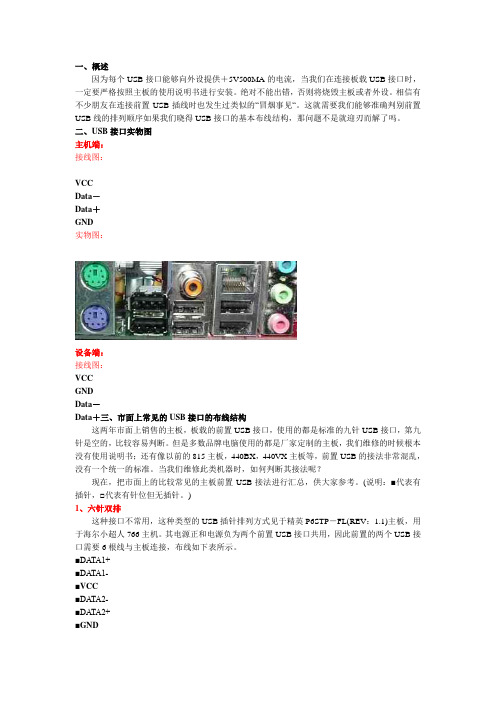
一、概述因为每个USB接口能够向外设提供+5V500MA的电流,当我们在连接板载USB接口时,一定要严格按照主板的使用说明书进行安装。
绝对不能出错,否则将烧毁主板或者外设。
相信有不少朋友在连接前置USB插线时也发生过类似的“冒烟事见“。
这就需要我们能够准确判别前置USB线的排列顺序如果我们晓得USB接口的基本布线结构,那问题不是就迎刃而解了吗。
二、USB接口实物图主机端:接线图:VCCData-Data+GND实物图:设备端:接线图:VCCGNDData-Data+三、市面上常见的USB接口的布线结构这两年市面上销售的主板,板载的前置USB接口,使用的都是标准的九针USB接口,第九针是空的,比较容易判断。
但是多数品牌电脑使用的都是厂家定制的主板,我们维修的时候根本没有使用说明书;还有像以前的815主板,440BX,440VX主板等,前置USB的接法非常混乱,没有一个统一的标准。
当我们维修此类机器时,如何判断其接法呢?现在,把市面上的比较常见的主板前置USB接法进行汇总,供大家参考。
(说明:■代表有插针,□代表有针位但无插针。
)1、六针双排这种接口不常用,这种类型的USB插针排列方式见于精英P6STP-FL(REV:1.1)主板,用于海尔小超人766主机。
其电源正和电源负为两个前置USB接口共用,因此前置的两个USB接口需要6根线与主板连接,布线如下表所示。
■DATA1+■DATA1-■VCC■DATA2-■DATA2+■GND2、八针双排这种接口最常见,实际上占用了十针的位置,只不过有两个针的位置是空着的,如精英的P4VXMS(REV:1.0)主板等。
该主板还提供了标准的九针接法,这种作是为了方便DIY在组装电脑时连接容易。
■VCC■DATA-■DATA+□NUL■GND■GND□NUL■DATA+■DATA-■VCC微星MS-5156主板采用的前置USB接口是八针互反接法。
虽然该主板使用的是Intel 430TX 芯片组,但首先提供了当时并不多见的USB1.0标准接口两个,只不过需要使用单独的引线外接。
- 1、下载文档前请自行甄别文档内容的完整性,平台不提供额外的编辑、内容补充、找答案等附加服务。
- 2、"仅部分预览"的文档,不可在线预览部分如存在完整性等问题,可反馈申请退款(可完整预览的文档不适用该条件!)。
- 3、如文档侵犯您的权益,请联系客服反馈,我们会尽快为您处理(人工客服工作时间:9:00-18:30)。
你清楚没有USB-C to USB-C E-marker 5A数据线
你是否真的需要TYPE-C芯片呢?为了让工程师对这个问题能够有一个简洁的判定标准。
笔者用三个原则来帮助大家进行这个判断:
第一原则:如果您希望通过USB TYPE-C接口来提供超过5V的电压,或者是超过3A的
流,那么一定需要TYPE-C接口芯片去实现USB PD协议。
第二原则:如果您的设备使用5V电压,并且不超过3A的电流。
那就要看设备本身的供电特性和数据传输特性。
如果设备本身只往外供电,或者只接受对方供电,并且供电角色与数据传输角色为默认搭配(即供电方为HOST,用电方为Slave或者device)。
那么你不需要TYPE-C芯片。
第三原则:这两个原则是用来判断设备上是否需要TYPE-C芯片,另外一点很受关注的C-C传输线上是否需要用到E-MARKER 芯片。
这个判断标准是,使用过程中,电流是否会超过3A?如果不超过,则可以不需要。
A to C, B to C的线,则看是否需要实现Battery Charging协议,如果要实现,则可以使用LDR6013,带来的好处是,既能够实现充电,又能够传输数据,避免某些不遵守Battery Charging协议的适配器无法给苹果设备充电的问题。
以上三个原则虽然可以帮助大家节省芯片,那怎么省呢?也要注意方法:
第一、用电方及Device这端。
用两个5.1K下拉电阻,分别连接到C口母座的CC1和CC2上。
如果需要判别插入方向,则用一个比较器,对两个电阻上的电压进行比较(如果是有处理器的系统,则可以用ADC 去判断),比较结果即为方向。
第二、供电方或者说HOST这端(供电电压为5V)。
用两个10K的上拉电阻分别对C口母座的CC1和CC2进行上拉。
如果需要判别插入方向的,则用一个比较器,对两个电阻上的电压进行比较(如果是有处理器的系统,则可以用ADC去判断),比较结果即为方向。
以上原则可以帮助工程师以及老板省下很多钱了,^_^,不过,肯定会有人要拍砖了。
Slaver端或者说SNK端别人不敢说什么?但是,SRC或者说,HOST这端,一定会有很多人跳出来,说这不符合TYPE-C标准,不能够随便往VBUS总线上放出电压。
我想说的是,确实不能随便放出去,比如放个9V,10V,15V的电压上去,会烧掉其他设备,但上面已经说了,前提是,你的工作电压是5V,放个5V电压到总线上,可能引发的问题是,两个5V相冲突了。
5V冲突之后会发生什么事情?实际做电源的人都明白,电压高者,会封住电压低者。
如果你很不幸,遇到对方的5V输出是PUSH PULL形式的,那么,确实有可能会引发灌电流的情况,但是,这种情况,属于电源设计本身应该处理的问题。
因此,如果要过USB-IF认证,那么,除了那种在适配器上直接伸出来不可拔除的USB 公头输出线之之外,其他DFP应用都乖乖的加上USB TYPE-C芯片吧。
如果不需要过认证,看着办吧。
有句话,叫做劣币驱逐良币,同样都能够用的情况下,市场会决定一切的。
目前,我能够看得到的必须要用TYPE-C芯片的应用,包括:笔记本电脑,手机,平板,移动电源,支持高压快充的适配器。
以上属一家之言,仅供参考,特别是总线上5V冲突的部分。
我之所以敢推荐不用芯片,那是因为即使用了,也很难避免不冲突,特别是两个DRP,两个TRY.SRC设备相连,并且外围存在干扰的情况下。
在Type-C 时代,所有的设计,都必须要应对总线上的VBUS电压冲突的情况。
既然都必须防冲突,那自然就可以不用了。
最后,还是附上基础知识:
与USB TYPE-C物理接口相关的标准一共有三个:USB Type-C 1.1, USB PD 2.0, Battery Charging1.2,如果3个协议全部支持,则可以实现Type-C的所有优势特性。
Type-C把设备的角色在供电和数据传输上进行了分离。
电能传输上分为 SRC(即供电方,例如适配器),SNK(即受电方,例如U盘)。
对于既能够承担SRC角色,又能够承担SNK角色的设备,则称为DRP设备(例如笔记电脑和手机)。
在DRP 设备中,有一类特别倾向于成为SRC设备的Device,称为Try.SRC设备(例如移动电源)。
数据传输角色上,分为 DFP(即传统的HOST)和UFP(即传统的Device或者Slave)默认情况下,SRC即为DFP,SNK即为UFP,如果要改变这种默认的搭配,则要使用USB PD 2.0通信协议进行ROLE_SWAP。
所有这些角色定义及角色切换,都是通过USB TYPE-C协议中的CC逻辑及通信来实现的。
深圳维力创科技电源适配器定制厂家,公司直销:电源适配器定制,笔记本电源适配器,电源适配器,微软笔记本电源适配器,PD协议快充,QC3.0/4+高通快充电源适配器及多口充电。