桥梁外文翻译
桥梁专业外文翻译--欧洲桥梁研究

桥梁专业外文翻译--欧洲桥梁研究附录Bridge research in EuropeA brief outline is given of the development of the European Union, together with the research platform in Europe. The special case of post-tensioned bridges in the UK is discussed. In order to illustrate the type of European research being undertaken, an example is given from the University of Edinburgh portfolio: relating to the identification of voids in post-tensioned concrete bridges using digital impulse radar.IntroductionThe challenge in any research arena is to harness the findings of different research groups to identify a coherent mass of data, which enables research and practice to be better focused. A particular challenge exists with respect to Europe where language barriers are inevitably very significant. The European Community was formed in the 1960s based upon a political will within continental Europe to avoid the European civil wars, which developed into World War 2 from 1939 to 1945. The strong political motivation formed the original community of which Britain was not a member. Many of the continental countries saw Britain’s interest as being purely economic. The 1970s saw Britain joining what was then the European Economic Community (EEC) and the 1990s has seen the widening of the community to a European Union, EU, with certain political goals together with the objective of a common European currency.Notwithstanding these financial and political developments, civil engineering and bridge engineering in particular have found great difficulty in forming any kind of common thread. Indeed the educational systems for University training are quite different between Britain and the European continental countries. The formation of the EU funding schemes —e.g. Socrates, Brite Euram and other programs have helped significantly. The Socrates scheme is based upon the exchange of students between Universities in different member states. The Brite Euram scheme has involved technical research grants given toconsortia of academics and industrial partners within a number of the states— a Brite Euram bid would normally be led by an industrialist.In terms of dissemination of knowledge, two quite different strands appear to have emerged. The UK and the USA have concentrated primarily upon disseminating basic research in refereed journal publications: ASCE, ICE and other journals. Whereas the continental Europeans have frequently disseminated basic research at conferences where the circulation of the proceedings is restricted.Additionally, language barriers have proved to be very difficult to break down. In countries where English is a strong second language there has been enthusiastic participation in international conferences based within continental Europe —e.g. Germany, Italy, Belgium, The Netherlands and Switzerland. However, countries where English is not a strong second language have been hesitant participants }—e.g. France.Post-tensioned concrete rail bridge analysisOve Arup and Partners carried out an inspection and assessment of the superstructure of a 160 m long post-tensioned, segmental railway bridge in Manchester to determine its load-carrying capacity prior to a transfer of ownership, for use in the Metrolink light rail system..Particular attention was paid to the integrity of its post-tensioned steel elements. Physical inspection, non-destructive radar testing and other exploratory methods were used to investigate for possible weaknesses in the bridge.Since the sudden collapse of Ynys-y-Gwas Bridge in Wales, UK in 1985, there has been concern about the long-term integrity of segmental, post-tensioned concrete bridges which may be prone to ‘brittle’ failure without warning. The corrosion protection of the post-tensioned steel cables, where they pass through joints between the segments, has been identified as a major factor affecting the long-term durability and consequent strength of this type of bridge. The identification of voids in grouted tendon ducts at vulnerable positions is recognized as an important step in the detection of such corrosion.Description of bridgeGeneral arrangementBesses o’ th’ Barn Bridge is a 160 m long, three span, segmental, post-tensioned concrete railway bridge built in 1969. The main span of 90 m crosses over both the M62 motorway and A665 Bury to Prestwick Road. Minimum headroom is 5.18 m from the A665 and the M62 is cleared by approx 12.5 m.The superstructure consists of a central hollow trapezoidal concrete box section 6.7 m high and 4 m wide. The majority of the south and central spans are constructed using 1.27 m long pre-cast concrete trapezoidal box units, post-tensioned together. This box section supports the in site concrete transverse cantilever slabs at bottom flange level, which carry the rail tracks and ballast.The center and south span sections are of post-tensioned construction. These post-tensioned sections have five types of pre-stressing:1. Longitudinal tendons in grouted ducts within the top and bottom flanges.2. Longitudinal internal draped tendons located alongside the webs. These are deflected at internal diaphragm positions and are encased in in site concrete.3. Longitudinal macalloy bars in the transverse cantilever slabs in the central span .4. Vertical macalloy bars in the 229 mm wide webs to enhance shear capacity.5. Transverse macalloy bars through the bottom flange to support the transverse cantilever slabs.Segmental constructionThe pre-cast segmental system of construction used for the south and center span sections was an alternative method proposed by the contractor. Current t hinking suggests that such a form of construction can lead to ‘brittle’ failure of the entire structure without warning due to corrosion of tendons across a construction joint,The original design concept had been for in site concrete construction.Inspection and assessmentInspectionInspection work was undertaken in a number of phases and was linked with the testing required for the structure. The initial inspections recorded a number of visible problems including:1、Defective waterproofing on the exposed surface of the top flange.2、Water trapped in the internal space of the hollow box with depthsup to 300 mm.3、Various drainage problems at joints and abutments.4、Longitudinal cracking of the exposed soffit of the central span.5、Longitudinal cracking on sides of the top flange of the pre-stressedsections.6、Widespread sapling on some in site concrete surfaces with exposedrusting reinforcement.AssessmentThe subject of an earlier paper, the objectives of the assessment were:1、Estimate the present load-carrying capacity.2、Identify any structural deficiencies in the original design.3、Determine reasons for existing problems identified by the inspection. Conclusion to the inspection and assessmentFollowing the inspection and the analytical assessment one major element of doubt still existed. This concerned the condition of the embedded pre-stressing wires, strands, cables or bars. For the purpose of structural analysis these elements、had been assumed to be sound. However, due to the very high forces involved,、a risk to the structure, caused by corrosion to these primary elements, was identified.The initial recommendations which completed the first phase of the assessment were:1. Carry out detailed material testing to determine the condition of hidden structural elements, in particularthe grouted post-tensioned steel cables.2. Conduct concrete durability tests.3. Undertake repairs to defective waterproofing and surface defects inconcrete.欧洲桥梁研究在欧洲,一个共同研究的平台随着欧盟的发展诞生了。
桥梁外文翻译
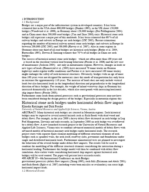
1 INTRODUCTION1.1 BackgroundBridges are a major part of the infrastructure system in developed countries. It has been estimated that in the USA about 600,000 bridges (Dunker 1993), in the UK about 150,000 bridges (Woodward et al. 1999), in Germany about 120,000 bridges (Der Prüfingenieur 2004) and in China more then 500,000 road bridges (Yan and Shao 2008) exist. Historical stone arch bridges still represent a major part of this multitude. It has been estimated that 60 % of all railway bridges and culverts in Europe are arch bridges (UIC 2005). Recent estimations regarding the number of historical railway natural stone arch bridges and culverts in Europe lie between 200,000 (UIC 2005) and 500,000 (Harvey et al. 2007). Also in some regions in Germany about one third of all road bridges are historical arch bridges (Bothe et al. 2004, Bartuschka 1995). Dawen & Jinxiang estimate that 70 % of all bridges in China are arch bridges.The success of historical natural stone arch bridges - which are often more than 100 years old- is based on the excellent vertical load bearing behaviour (Proske et al. 2006) and the low cost of maintenance (Jackson 2004) - not only in mountainous regions. However, changes in loads or new types of loads (Hannawald et al. (2003) have measured 70 tonne trucks on German highways under regular traffic conditions and Pircher et al. have measured 100 tonne trucks) might endanger the safety of such historical structures. Obviously, bridges with an age of more than 100 years were not designed for motorcars since this mode of transportation has only been in existence for approximately 110 years. The increase of loads does not only include vertical loads but also horizontal loads in the longitudinal direction and perpendicular to the longitudinal direction of these bridges. For example, the weight of inland waterway ships in Germany has increased dramatically in the last decades, which also corresponds with increasing horizontal ship impact forces (Proske 2003).Furthermore some loads from natural processes such as gravitational processes may not have been considered during the design process of the bridges. Especially in mountain regions this Historical stone arch bridges under horizontal debris flow impact Klaudia Ratzinger and Dirk ProskeUniversity of Natural Resources and Applied Life Sciences, Vienna, AustriaABSTRACT: Many historical arch bridges are situated in Mountain regions. Such historical bridges may be exposed to several natural hazards such as flash floods with dead wood and debris flows. For example, in the year 2000 a heavy debris flow destroyed an arch bridge in Log Pod Mangartom, Slovenia and only recently, in September 2008 an arch bridge was overflowed by a debris flow. A new launched research project at the University of Natural Resources and Applied Life Sciences, Vienna tries to combine advanced numerical models of debris flows with advanced models of historical masonry arch bridges under horizontal loads. The research project starts with separate finite element modelling of different structural elements of arch bridges such as spandrel walls, the arch itself, roadway slabs, pavements and foundations under single and distributed horizontal loads. Furthermore miniaturized tests are planned to investigate the behaviour of the overall bridge under debris flow impacts. The results will be used to combine the modelling of the different structural elements considering the interaction during a horizontal loading. Furthermore this bridge model will then be combined with debris flow simulation. Also earlier works considering horizontal ship impacts against historical arch bridges will be used control. The paper will present latest research results.400 ARCH’10 – 6th International Conference on Arch Bridgesgravitational processes (debris flow impacts (Zhang 1993), rock falls (Erismann and Abele 2001) and flash floods (Eglit et al. 2007) including water born missiles or avalanches) can cause high horizontal impact loads.1.2 Historical EventsIn the year 2000, a debris flow destroyed two bridges in Log Pod Mangartom, Slovenia, one of them was a historical arch bridge. In October 2007 the historical arch bridge in Beniarbeig, Spain was destroyed by a flash flood. Similarly the Pöppelmann arch bridge in Grimma, Germany was destroyed in 2002, in 2007 a farm track and public footpath arch bridge over the River Devon collapsed.Figure 1: Debris flow impact at the Lattenbach (Proske & Hübl, 2007)Fig.1 shows an example of the historical arch bridge at the Lattenbach, before and after a debris flow event, where the bridge is nearly completely filled with debris.Due to far too expensive solutions or not applicable methods for historical arch bridges it would be very useful if models were available to estimate the load bearing capacity of historical masonry arch bridges for horizontal loads perpendicular to the longitudinal direction.Since intensive research was carried out for the development of models dealing with vertical loads for historical arch bridges, there is an unsurprising lack of models capable for horizontal impact forces against the superstructure. This might be mainly based on the assumption that horizontal loads are not of major concern for this bridge type due to the great death load of such bridges.The goal of this investigation is the development of engineering models describing the behaviour of historical natural stone arch bridges under horizontal forces, mainly debris flow impacts, focused strongly on the behaviour of the superstructure and based on numerical simulations using discrete element models and finite element models.2 INNOVATIVE ASPECT AND GOALS2.1 Innovative AspectsThe conservation of historical arch bridges is not only an issue of the preservation of cultural heritage but is also an economic issue since the number of historical bridges in developed countries is huge (Proske 2009). Compared to vertical load cases no models currently exist for horizontal loads perpendicular to the longitudinal direction. It is therefore required to develop new models dealing with these capacious horizontal loads which include all types of gravitational hazards like avalanches, debris flow, rock falls or flood borne missiles or impacts from modes of transportation. First works related to the development of debris flow design impact forces and the behaviour of arch bridges under such an impact have started already 2007 at the Institute of Alpine Mountain Risk Engineering at the University of Natural Resources and Applied Life Sciences, Vienna (see Fig.2)Klaudia Ratzinger and Dirk Proske 401Figure 2 : Examples of the structural behaviour under impacts (left against the pier, right against the arch itself) (Proske and Hübl 2007)This investigation and its results regarding debris flow impact will flow into the development of the new Austrian code of practice Ö-Norm 24801 for the design of structures exposed to debris flow impacts as well.2.2 GoalTo develop load bearing behavior models of historical natural stone arch bridges under horizontal loads perpendicular to the longitudinal direction, a realistic model of debris flow against solid structures has to be implemented indifferent programs. Separate finite element modelling of different structural elements of arch bridges such as spandrel walls, the arch itself, roadway slabs, pavements and foundations under single and distributed horizontal loads are part of this investigation. Furthermore miniaturized tests are part of the project to investigate the behaviour of the overall bridge under debris flow impacts. The results will be used to combine the modelling of the different structural elements considering the interaction during a horizontal loading. Furthermore this bridge model will then be combined with debris flow simulation. Also earlier works considering horizontal ship impacts against historical arch bridges will be used. Therefore three models of historical arch bridges are developed:(1) Discrete element program model (PFC),(2) Explicit finite difference program model (FLAC),(3) Finite element program model (ANSYS, ATENA).The first and second models are developed to simulate an overall debris flow impact scenario, whereas the third model is used to investigate details, such as single force against a spandrel wall, single force against parapets, friction at the arch, single impact force against the arch. Results from the impact simulation against the superstructure should give an answer, whether the complete process can be separated into forces acting on the bridge. This reference force (force-time-function) will then be applied on the finite element models.The numerical modelling will be accompanied by testing to permit validation of the models. The tests will be carried out as miniaturized tests (scale about 1:20…50). Already miniaturized tests of the impact of debris flows against debris flow barriers were already carried out at the Institute of Mountain Risk Engineering (Proske et al. 2008, Hübl & Holzinger 2003,Fig.3). Based on this experience, miniaturized arch bridges (span about 40 to 50 cm) will be constructed and investigated. Also single parts of the arch structure will be investigated in testing machines, such as behaviour of a pure arch under a horizontal load. Since the machine cannot be turned, force redirection mechanisms will be used to allow the application of a standard compression test machine from the University of Natural Resources and Applied Life Sciences, Vienna.402 ARCH’10 – 6th International Conference on Arch BridgesFigure 3 : Side view and view from above of the used debris flow impact measurement test set-up (Hübl & Holzinger 2003)3 CALCULATIONS3.1 Discrete element methodsDiscrete element modeling can be done by usingPFC3D (Particle Flow Code 3D) which is used in analysis, testing and research in any field where the interaction of many discrete objects exhibiting large-strain and/or fracturing is required. By using the program PFC3D, materials can be modeled as either bonded (cemented) or granular assemblies of particle s.3.2 Finite element methodsThe finite element method (FEM) is one of the most powerful computer methods for solving partial differential equations applied on complex shapes and with complex boundary conditions.A mesh made of a complex system of points is programmed containing material and structural properties defining the reaction of the structure to certain loading conditions. Nodes are assigned at a certain density throughout the material depending on the anticipated stress levels of a certain area.Two types of analysis are commonly used: 2-D modelling and 3-D modelling. 2-D modelling allows the analysis to be run on a normal computer but tends to yield less accurate results whereas 3-D modelling shows more accurate results.For this investigation two FEM programs are used:(1) ANSYS(2) ATENAANSYS is the leading finite element analysis package for numerically solving a wide varietyof mechanical problems in 2D and 3D. By using ANSYS, the analysis can be done linear and non-linear, is applicable to static and dynamic structural analysis, heat transfer and fluid problems as well as acoustic and electromagnetic problems.The ATENA program is determined for nonlinear finite element analysis of structures, offers tools specially designed for computer simulation of concrete and reinforced concrete structural behaviour. Moreover, structures from other materials, such as soils, metals etc. can be treated as well.In the first step finite element methods are used to simulate the behaviour of historical natural stone arch bridges under an impact. Required data for the debris flow models are taken from the database of the Institute of Mountain Risk Engineering as well from the Austrian RailwayService (ÖBB).Klaudia Ratzinger and Dirk Proske 403The basic requirements for an appropriate assessment of stone arch bridges are:(1) Choice of a realistic calculation model(2) Consideration of geometrical and material nonlinearities(3) Using applicable material models for masonry(4) Adapted evidence based on the chosen material models.Therefore, a simplified arch bridge model with various lengths (L), rising of the vault (r) and thickness of the stone arch (t) was chosen (Fig.4) – first by using a two-dimensional model –with the purpose to investigate the importance of geometrical properties to their structural performance and to demonstrate different results. Further models are in process and will be implemented in the FEM programs as well.Figure 4 : FE model of a simplified arch bridge (Becke, 2005)4 CONCLUSIONSThis research project launched by the University of Natural Resources and Applied Life Sciences, Vienna combines advanced numerical models of debris flows with advanced models of historical masonry arch bridges under horizontal loads. It started with the implementation of separate finite element modelling of different structural elements of arch bridges. Furthermore miniaturized tests will be done in 2010 to investigate the behaviour of the overall bridge under debris flow impacts. The results will be used to combine the modelling of the different structural elements considering the interaction during a horizontal loading and the bridge model will be combined with debris flow simulation.Last but not least recommendation values for such bridge types should be given by this investigation that may include further formulas considering for example the adaptation of masonry stiffness or strength values.1介绍1.1背景桥梁是发达国家的基础设施系统的一个主要部分。
外文翻译---桥梁工程和桥梁美学

附录3 外文文献翻译BRIDGE ENGINEERING AND AESTHETICS Evolvement of bridge Engineering,brief reviewAmong the early documented reviews of construction materials and structure types are the books of Marcus Vitruvios Pollio in the first century B.C.The basic principles of statics were developed by the Greeks , and were exemplified in works and applications by Leonardo da Vinci,Cardeno,and Galileo.In the fifteenth and sixteenth century, engineers seemed to be unaware of this record , and relied solely on experience and tradition for building bridges and aqueducts .The state of the art changed rapidly toward the end of the seventeenth century when Leibnitz, Newton, and Bernoulli introduced mathematical formulations. Published works by Lahire (1695)and Belidor (1792) about the theoretical analysis of structures provided the basis in the field of mechanics of materials .Kuzmanovic(1977) focuses on stone and wood as the first bridge-building materials. Iron was introduced during the transitional period from wood tosteel .According to recent records , concrete was used in France as early as 1840 for a bridge 39 feet (12 m) long to span the GaroyneCanal at Grisoles, but reinforced concrete was not introduced in bridge construction until the beginning of this century . Prestressed concrete was first used in 1927.Stone bridges of the arch type (integrated superstructure and substructure) were constructed in Rome and other European cities in the middle ages . These arches were half-circular , with flat arches beginning to dominate bridge work during the Renaissance period. This concept was markedly improved at the end of the eighteenth century and found structurally adequate to accommodate future railroad loads . In terms of analysis and use of materials , stone bridges have not changed much ,but the theoretical treatment was improved by introducing the pressure-line concept in the early 1670s(Lahire, 1695) . The arch theory was documented in model tests where typical failure modes were considered (Frezier,1739).Culmann(1851) introduced the elastic center method for fixed-end arches, and showed that three redundantparameters can be found by the use of three equations of coMPatibility.Wooden trusses were used in bridges during the sixteenth century when Palladio built triangular frames for bridge spans 10 feet long . This effort also focused on the three basic principles og bridge design : convenience(serviceability) ,appearance , and endurance(strength) . several timber truss bridges were constructed in western Europe beginning in the 1750s with spans up to 200 feet (61m) supported on stone substructures .Significant progress was possible in the United States and Russia during the nineteenth century ,prompted by the need to cross major rivers and by an abundance of suitable timber . Favorable economic considerations included initial low cost and fast construction .The transition from wooden bridges to steel types probably did not begin until about 1840 ,although the first documented use of iron in bridges was the chain bridge built in 1734 across the OderRiver in Prussia . The first truss completely made of iron was in 1840 in the United States , followed by England in 1845 , Germany in 1853 , and Russia in 1857 . In 1840 , the first iron arch truss bridge was built across the Erie Canal at Utica .The Impetus of AnalysisThe theory of structuresThe theory of structures ,developed mainly in the ninetheenth century,focused on truss analysis, with the first book on bridges written in 1811. The Warren triangular truss was introduced in 1846 , supplemented by a method for calculating the correcet forces .I-beams fabricated from plates became popular in England and were used in short-span bridges.In 1866, Culmann explained the principles of cantilever truss bridges, and one year later the first cantilever bridge was built across the MainRiver in Hassfurt, Germany, with a center span of 425 feet (130m) . The first cantilever bridge in the United States was built in 1875 across the Kentucky River.A most impressive railway cantilever bridge in the nineteenth century was the First of Forth bridge , built between 1883 and 1893 , with span magnitudes of 1711 feet (521.5m).At about the same time , structural steel was introduced as a prime material inbridge work , although its quality was often poor . Several early examples are the Eads bridge in St.Louis ; the Brooklyn bridge in New York ; and the Glasgow bridge in Missouri , all completed between 1874 and 1883.Among the analytical and design progress to be mentioned are the contributions of Maxwell , particularly for certain statically indeterminate trusses ; the books by Cremona (1872) on graphical statics; the force method redefined by Mohr; and the works by Clapeyron who introduced the three-moment equations.The Impetus of New MaterialsSince the beginning of the twentieth century , concrete has taken its place as one of the most useful and important structural materials . Because of the coMParative ease with which it can be molded into any desired shape , its structural uses are almost unlimited . Wherever Portland cement and suitable aggregates are available , it can replace other materials for certain types of structures, such as bridge substructure and foundation elements .In addition , the introduction of reinforced concrete in multispan frames at the beginning of this century imposed new analytical requirements . Structures of a high order of redundancy could not be analyzed with the classical methods of the nineteenth century .The importance of joint rotation was already demonstrated by Manderla (1880) and Bendixen (1914) , who developed relationships between joint moments and angular rotations from which the unknown moments can beobtained ,the so called slope-deflection method .More simplifications in frame analysis were made possible by the work of Calisev (1923) , who used successive approximations to reduce the system of equations to one simple expression for each iteration step . This approach was further refined and integrated by Cross (1930) in what is known as the method of moment distribution .One of the most import important recent developments in the area of analytical procedures is the extension of design to cover the elastic-plastic range , also known as load factor or ultimate design. Plastic analysis was introduced with some practical observations by Tresca (1846) ; and was formulated by Saint-Venant (1870) , The concept of plasticity attracted researchers and engineers after World War Ⅰ , mainly inGermany , with the center of activity shifting to England and the United States after World War Ⅱ.The probabilistic approach is a new design concept that is expected to replace the classical deterministic methodology.A main step forward was the 1969 addition of the Federal Highway Adiministration (FHWA)”Criteria for Reinforced Concrete Bridge Members “ that covers strength and serviceability at ultimate design . This was prepared for use in conjunction with the 1969 American Association of State Highway Offficials (AASHO) Standard Specification, and was presented in a format that is readily adaptable to the development of ultimate design specifications .According to this document , the proportioning of reinforced concrete members ( including columns ) may be limited by various stages of behavior : elastic , cracked , and ultimate . Design axial loads , or design shears . Structural capacity is the reaction phase , and all calculated modified strength values derived from theoretical strengths are the capacity values , such as moment capacity ,axial load capacity ,or shear capacity .At serviceability states , investigations may also be necessary for deflections , maximum crack width , and fatigue .Bridge TypesA notable bridge type is the suspension bridge , with the first example built in the United States in 1796. Problems of dynamic stability were investigated after the Tacoma bridge collapse , and this work led to significant theoretical contributions Steinman ( 1929 ) summarizes about 250 suspension bridges built throughout the world between 1741 and 1928 .With the introduction of the interstate system and the need to provide structures at grade separations , certain bridge types have taken a strong place in bridge practice. These include concrete superstructures (slab ,T-beams,concrete box girders ), steel beam and plate girders , steel box girders , composite construction , orthotropic plates , segmental construction , curved girders ,and cable-stayed bridges . Prefabricated members are given serious consideration , while interest in box sections remains strong .Bridge Appearance and AestheticsGrimm ( 1975 ) documents the first recorded legislative effort to control the appearance of the built environment . This occurred in 1647 when the Council of New Amsterdam appointed three officials . In 1954 , the Supreme Court of the United States held that it is within the power of the legislature to determine that communities should be attractive as well as healthy , spacious as well as clean , and balanced as well as patrolled . The Environmental Policy Act of 1969 directs all agencies of the federal government to identify and develop methods and procedures to ensure that presently unquantified environmental amentities and values are given appropriate consideration in decision making along with economic and technical aspects .Although in many civil engineering works aesthetics has been practiced almost intuitively , particularly in the past , bridge engineers have not ignored or neglected the aesthetic disciplines .Recent research on the subject appears to lead to a rationalized aesthetic design methodology (Grimm and Preiser , 1976 ) .Work has been done on the aesthetics of color ,light ,texture , shape , and proportions , as well as other perceptual modalities , and this direction is both theoretically and empirically oriented .Aesthetic control mechanisms are commonly integrated into the land-use regulations and design standards . In addition to concern for aesthetics at the state level , federal concern focuses also on the effects of man-constructed environment on human life , with guidelines and criteria directed toward improving quality and appearance in the design process . Good potential for the upgrading of aesthetic quality in bridge superstructures and substructures can be seen in the evaluation structure types aimed at improving overall appearance .LOADS AND LOADING GROUPSThe loads to be considered in the design of substructures and bridge foundations include loads and forces transmitted from the superstructure, and those acting directly on the substructure and foundation .AASHTO loads . Section 3 of AASHTO specifications summarizes the loads and forces to be considered in the design of bridges (superstructure and substructure ) .Briefly , these are dead load ,live load , iMPact or dynamic effect of live load , wind load , and other forces such as longitudinal forces , centrifugal force ,thermal forces , earth pressure , buoyancy , shrinkage and long term creep , rib shortening , erection stresses , ice and current pressure , collision force , and earthquake stresses .Besides these conventional loads that are generally quantified , AASHTO also recognizes indirect load effects such as friction at expansion bearings and stresses associated with differential settlement of bridge components .The LRFD specifications divide loads into two distinct categories : permanent and transient .Permanent loadsDead Load : this includes the weight DC of all bridge components , appurtenances and utilities, wearing surface DW and future overlays , and earth fill EV. Both AASHTO and LRFD specifications give tables summarizing the unit weights of materials commonly used in bridge work .Transient LoadsVehicular Live Load (LL)Vehicle loading for short-span bridges :considerable effort has been made in the United States and Canada to develop a live load model that can represent the highway loading more realistically than the H or the HS AASHTO models . The current AASHTO model is still the applicable loading.桥梁工程和桥梁美学桥梁工程的发展概况早在公元前1世纪,Marcus Vitrucios Pollio 的著作中就有关于建筑材料和结构类型的记载和评述。
大桥用英语怎么说

大桥用英语怎么说篇一:桥梁英文翻译ThemAInpRobLemsoFDomesTIcbRIDgeDesIgnIngnow,thecountry'sstructuraldesignprocess,suchtendencies:moreintensitycon sideredinthedesignanddurabilityconsiderlessattentionintensitylimittotheus eofstatewithoutlimitstate,andthroughoutthelifecycleofthemostimportantw henitispreciselytheuseofperformance;attentiontotheconstructionofthestruc turewithoutattentiontothemaintenanceofthestructure.Infact,thecurrentdesi gnofthebridgeformoredurabilityisaconcern,asaconcept,didnotexplicitlyput forwardtherequestoftheuseoflife,northedurabilityofspecializeddesign.Thes etendenciestoacertainextent,ledtothecurrentprojectaccidents,theuseofpoor performance,theshortlifeoftheadverseconsequencesofstructuralengineerin gwiththeincreasingemphasisoninternationaldurability,safety,contrarytothet rendofapplicability;doesnotconformtothestructuredynamicandcomprehens iveeconomyrequirements.bridgesafety,durability,themainreasonforpoor1)constructionandmanagementoflowlevel morebridgesathomeandabroaddestructionandthesuddencollapseofthebridg ehasbeenengineeringmoreconcernedaboutsecurityissues.Thegeneralviewi sthatthecurrentprojectisbarbaricincidentmanagementandconstructioncausedbycorruption.Fortheshortterm,suchasthedestructionandcollapseofasudde n,mostlybecauseofconstructionqualitydidnotmeetspecificationsanddesignr equirements,typicalproblemsincludeinadequateandconstructionmaterialsi ntensityoffailure;alsoexist,suchasindividualbridgejerryseriousmanagemen tissues,butalsoonbridgesafetyofthefataldamage. Andalargenumberofbridgesinthefardidnotachievetheexpectedlifetime,ther ehasbeenaffectingthenormaluseofdiseaseanddeterioration,especiallyinanu mberofbridgesinuseonlyafewyears,orevenjustcompletedsoonontheserious problemofinsufficientdurability,whichandthelowqualityofconstructionisan importantrelationship,thetypicalproblemsofinadequateprotectionofreinfor cedandthecurrentwidespreadintheconstructionsiteoftheseriousproblemofcr ackingcomponent.Theseconstruction,althoughshort-termdeficienciesofthe bridgewillnotbethenormaluseofaclearimpact,butthelong-termdurabilityoft hestructurewillhaveaverynegativehazards.2)Designtheoryandstructureofthesystemisnotperfectenough whileacknowledgingtheexistenceoftheproblem,butitalso,itisundeniabletha tbridgedesignfields,inparticularonthebridgeconstructionanduseoftheissueo fsafetythereisstillmuchimprovement.structuraldesignfirstandforemosttaski sthechoiceofreasonableeconomicprogrammer,followedbythestructuralanal ysisanddesignofcomponentsandconnections,andaccesstoregulatethesafety factorspecifiedorreliabilityofindicatorstoensurethesafetyofthestructure. manydesignersoftencomplacentwithnormsonthestructuralstrengthofthesafetyoftheneed,andignorethestructuralsystem,structure,structure,structureof materials,structuremaintenance,aswellasfromthestructuraldurabilityofthed esignandconstructionprocesstomakeuseofthatoftenappearintheman-made wrongareastostrengthenandguaranteethesafetyofthestructure.somestructur alintegrityandductilityinadequateredundancysmall,butsomeofschemaandt heuncertaintyoftheline,causingpartialexcessiveforce;someconcretestrengt hgradetoolowtoprotectslicethroughsmalldiametersteelmicromanage,athinc ross-sectioncomponentsofthesestructureshaveweakenedthedurability,itwo uldseriouslyaffectthesafetyofthestructure.manybridges,althoughthedesign specificationsmeettherequirementsofthestrengthofonly5to10yearsbecause ofthedurabilityoftheproblemsaffectingstructuralsafety.structuralDurability shortagehasbecomeoneofthemostrealisticsecurityissues,fromdesigntocons tructionandmaterials,suchasangleofmeasurestostrengthenthedurabilityofth estructure. oftheenvironmentandtheuseofdifferentconditions,differentdesignofthestru cturalsystemwilltargetdifferentaspectsofthelayoutandstructurerequirement s.normscannotcoverindetailthedesignstaffshouldsolvethevariousproblemsi ntheupdatednormsfastercanalsoadapttonewunderstanding,newtechnologie s,newmaterials,rapiddevelopmentofthestructureofthenewrequirements.Th erefore,reasonableandreliableadditiontothestructuresisdesignedtomeetther equirementsofnorms,andtodesignastructuretothecorrectunderstandingofna ture,richexperienceandaccuratejudgments.Andtheneedtoimproveeffortsinthedirection1)shouldpaymoreattentiontothedurabilityofstructuralproblems bridgeintheconstructionanduseoftheprocess,willbesubjecttoenvironmental ,andtheerosionofharmfulchemicalsubstances,andtobearvehicles,wind,eart hquake,fatigue,overloading,humanfactors,suchasexternalrole,andbridgem aterialsusedbytheself-degradationofperformancewillcontinue,resultinginth estructureofthedifferentdegreesofdamageanddeterioration.Inthefieldoflon g-spanbridges,andfromthecountrysincethe1980s,theconstructionofalargen umberofcable-stayedbridge,althoughsofartherecollapseorseriousdamageto thefewexamples,buthasmorebridgesbecauseofthedurabilityofcabletothepr oblemadvanceforcable,andthisnotonlyaffectstheuseofincreasedeconomicl osses. needstobepointedoutisthatmanyoftheseproblemsanddidnotconductareason abledurabilityofthedesign,whichhasalsopromptedrenewedawarenessofdur abilityofthebridge.Diseasesarealotofexamplesofthat,inadditiontoconstructi onmaterialsandthereasonsforadecisiveimpactonthedurabilityofthestructure fromthestructuralfactors(isdesign)flaws.Fromthecountryinthe1990sstartedtoattachimportancetothedurabilityofthes tructureofthestudy,hasalsomadequiteafewsuccesses.mostofthesestudiesan dstatisticsfromtheanalysisofthematerialpointofview,onhowtostructureandd esignfromtheperspectiveofhowandthedesignandconstructionstafftobereadi lyacceptedandoperationofthebridgeapproachtoimprovingthedurabilityhasbeenlittleresearch.moreover,foralongtime,peoplehavealwaysbeenemphasis onthemethodsofcalculationonthestructure;itignoresthedetailsoftheoverallst ructureandprocessingconcern.Designanddurabilityofthestructureofthestru cturaldesignofaconventionalnatureofthedifferencebetweenthecurrenteffort swillbeneededonthedurabilityofthequalitativeanalysistothequantitativeana lysisofdevelopment.2)emphasisonthestudyoffatiguedamage bridgestructuretowithstandthevehicleloadandwindloadaredynamicloadwill beinacycleofchangewithinthestructureofthestress,notonlywillcausethevibr ationofthestructure,butalsofromthestructureofthe accumulatedfatiguedamage. Thebridgeisnotusedbythematerialisuniformandcontinuous,infacttherearem anytinyflawsintheroleofcyclicloading,thesedeficiencieswillbeprogressived evelopmentofmicro,amergerofinjury,andgraduallyformedinthematerialma crocracks.Ifthecrackisnoteffectivemacro-control,isverylikelytocausemater ial,thestructureofbrittlefracture.earlyfatiguedamageisnotalwayseasytobede tected,buttheconsequencesareoftendisastrous. Fatiguedamagehasbeenconsideredinthedesignofsteelbridgeisthecoreissueo ffatiguecausedbythesteelstructureofsteelcrackmorecases,manycausedbyfat iguefracturebridgecollapseexample.overthepast20years,fatigueinjuryresea rchhasenteredtheconcretestructure,butbytheuseofcorrosionofreinforcedco ncretestructuresdynamicperformanceandfatiguepropertiesofneedtobestrengthened. onthefatiguedamageofnotonlyreferstotheentirestructure,thebridgestructure oftenasamatteroffactsomeofthekeypartsoflocalfatiguefailureoftheentirestr uctureandleadtofailure,suchasthecable-stayedbridgecablesanchoringendof thefatiguedamage.3)payfullattentiontotheproblemofoverloadingthebridge Therearethreemainvehicleoverloading:oneistheearlyconstructionoftheoldb ridgeoverageloadcarriersandtheotheristhepassageofvehiculartrafficbridge overtheoriginaldesign;theotherisillegaloverloadingofvehicles.Thefirsttwo arethemainreasonsforthechangesinthedesignloadandtheincreaseinthevolu meoftraffic;usersofthelatterareillegaloverloadingofvehiclesoperating,thela ttertwophenomenaofoverloadinginroadtransportinchinaismorecommon. ontheonehand,overloadingthebridgemaytriggerfatigue.overloadingbridge wouldincreasetherateoffatiguestressinjuryaggravated,orevensomestructura ldamagecausedbyoverloadingaccidents.ontheotherhand,duetooverloading ofthebridgecausedinternaldamagecannotberestored,thebridgewillbemadeo ftheworkundernormalloadconditionschange,whichcouldendangerthesafety ofbridgesanddurability.Forexample,theconcretebridgehasalwaysbeenregar dedasanadequatedurability,buttheoverloadingofthevehicle,crackingmayoc cur;cracksevenintheloadwillbeabletodivestclosed,buttheinternalstructureo fconcretehasbeendamage,crackingcomponentfromthelowerbend,stiffnessdeclinewasinthenormaluseofload,shouldnothavebeencrackingorstructuralcrackshavebecomesmallercracksinexcessofthenormsto allowalargercracksordeformation.Thesewillbeusedforstructuralperforman ceandlong-termdurabilityhasanegativeimpact,inadditiontotheTrafficcontro ldepartmentsshouldstrengthenmanagement,butalsotheneedforoverloadingt heconsequencesofresearch,analysis.4)Activelylearnfromforeignexperienceandresults Domesticbridgedesignthemainproblemsistheuseofthenormalstructureofpo orperformance(referringcomparedwiththedesignexpectationscanbeattribut edtopoorperformanceoftheapplication,includingthebridgetoomuchvibratio n,linearirregularity,joints,diarrhea,excessivestructuralcrackinganddeforma tion,etc.),durabilityandsafetyofthepoor(includingshortlifespan,highmainte nancecosts,andmorefrequentaccidents,etc.).whiletheseissueshavewiththec urrentdomesticconstructionqualityandmanagementlevellower,buttobefair, sincethissituationcannotberesolvedintheshortterm,thenasengineersweshou ldaddressthisissueinthepremise,arefullytakenintoaccountstageofconstructi onandmanagementandmaterialstechnology,theuseofappropriatesecurity,th eappropriatewaytoensurethatthedesignofabridgetotheuseoftheperformance ,thisisamoreproactiveandeffectivemeans.especiallythedurabilityofthebridg eandsafetyofmanyproblemswiththestructureortheuseofmaterialselectionar eueasonableandimproperhandlingofthestructuraldetails. Ineuropeancountries(suchasgermany,Denmark,etc.),attachedgreatimporta ncetothestructureofaperformance-baseddesign(pbD,performancebasedDesign),whichincludesstructuraldeformation,cracks,vibration,strong,handsom e,durability,fatigueandsoon.pbDstudyistoenableoperatorsinthestructureoft heprocess,inadditiontotheguaranteedminimumsecurityrequirements;theide aoftheuseofperformanceshouldbegood(includinglifeanddurability,corrosio nresistance,fatigueresistance,aesthetics,etc.).bytheirverynature,theeuropea ncountriespbDtheory,researchintheuseofstructureinthecourseofperforman ceoutofservice,theperformancebytheweakeningofthereasonsforitsoccurren ceandthemechanismofthelaw,toseekanewstructuraldesignconceptsandmet hods.Fromthepointofviewofeuropeans,pbDseemstobetothedurabilityofthestruct ureatthecoreofthecomprehensiveuseofperformanceindicatorsto篇二:道路桥梁专业英语翻译Lesson1careersincivilengineering(土木工程中的各种业务)土木工程是一个意味着工程师必须要经过专门的大学教育的职业。
毕业英文文献翻译 bridge 桥

河北农业大学现代科技学院毕业英文文献翻译题目:Bridge学部:工程技术学部专业班级:土木0603班学号:2006614100322学生姓名:周炯指导教师姓名:宇云飞指导教师职称:副教授二〇一〇年五月二十一日The Road of ChinaABSTRACTKey words:express way,In 1981,China had only 17,500km of road, 400km of motorway and 4,000km of highway and 2,300km of regional road. Around 75% of these roads were paved. By the end of 1922, these figures had changed dramatically, with the total being over a million kilometers of highways. Of this, 926,452km were paved(92%), linking all the major towns in the country, with the exception of Motuo in Tibet.Present figures indicate that more than 70% of villages and towns are now connected to the highway network. Four major highways link Lhasa with Sichun, Xinjiang, Qinghai Hu and Kathmandu (Nepal).A programme of expressway building began in the mid 1980s and by 1993 there were more than 522km of these high speed links, including Shenyang to Dalian, Beijing to Tanggu, Shanghai to Jiading, Guangzhou to Foshan and Xi’an to Linton.So who is using these road? The general public’s impression of China is people on bicycles, but this is now changing. Since 1977 , the number of privately-owned passenger cars has increased by over 4,000% to 2.3mil. and the number of commercial vehicles produced has increased from 328,000 to nearly 500,000.As with most products, the demand for an increased number of better quality roads drives the supply, and the upwardly mobile Chinese, as well as industry, are forcing investment in a better and much more comprehensive infrastructure system.The Chinese government has recognized the need for investment in infrastructure and finance minister Liu Zhongli has announced that more than $500bil. will be allocated to the infrastructure over the next decade, “We need to raise funds internationally, either through bond issues or through loans provided by international financial institutions and foreign governments”.China is definitely attracting investment. A recent report in Development Business said, “China is gaining prominence in the portfolio of the International Finance Corporation(IFC),as the World Bank Group’s private sector arm adopts strategies that will dovetail neatly with Beijing’s own priorities.”The central government has announced its intention to focus on projects along the Yangtze River, beginning at Shanghai and ending at the province of Sichuan, with special emphasis on infrastructure.In Shanghai alone, transport and planning officials have said that the city needs an investment of at least $17bil. over the next four years to develop the road infrastructure network. Over the last five years, the city has relied on World Bank, Asian Development Bank and foreign government loans to fund its infrastructure development. It has also tried, on a limited basis, the build-operate-transfer method, toattract foreign capital for a multi-track tunnel and has contracted out the management of two bridges and a road tunnel.Part of the Ninth Five-year plan, which started this year, covers the construction of three east-west trunk road, three north-south trunk roads and a light rail system.One of the major projects under consideration is the consideration of the Hebei and Liaoning Expressways, which the government describes as, “an attempt to alleviate constraints to further economic growth that caused by the inadequate road transport infrastructure in the area.”The intention is to improve access to the hinterland economics of the respective provinces and to reduce pressure on the rail network. The Hebei Project will cover the development of approximately 200km of the Beijing to Shenyang Expressway, while the Liaoning Project will cover about 110km of the northeastern transport corridor from Teiling to Siping.On the outer edges of the infrastructure policy, the Chinese government has invest nearly $18mil. on road projects in Tibet, including the $17mil. project to improve the highway between Sichuan and Tibet and the road linking Gonggar airport at Lhasa and Zetang in southern Tibet.Recent reports show that Wuhan city in Hubei Province has spent more than $2bil. of overseas funds in building 200 infrastructure projects since 1985, including the construction of the ChangJiang River highway bridge, with another bridge planned over the Hanshui River.Several large European road machinery equipment manufacturers are having considerable success in China, and German company Wirtgen has provided machinery for a number of major projects, including the new Shenzen to Shantou Expressway. The contractor, the Guizhou Provincial Road and bridge Company, is refurbishing 146km of the six-lane highway with funding from the World Bank.A smaller (33km) new concrete pavement section of the same road is being constructed by the Pavement Division of the local company, again funded by the World Bank. On the other side of the pearl River Delta, Wirtgen machines are also paving part of the 80km long Foshan to Kaiping Expressway.American company CMI has delivered equipment to the Jiangsu Road and Bridge Construction Corporation for use on the 284km-long Shanghai-Nanjing Expressway. Construction is partly financed by Japanese and partly by Malaysian investors. CMI equipment is also working on the Huadu Highway in Guangzhou and the Yantai-Weihai Highway.The number over the last few years has not been attracting the investment—that seems to be going fairly well for the Chinese, fuelled by western companies’ greed for what they see as the last great market in the world—but finding the specialist consultants and planners to develop the infrastructure and to ensure a tight grip on the reins of large scale developments, to prevent sprawling messes emerging across the nation.It has become apparent that the indigenous infrastructure planning and design industry is not yet sophisticated enough to undertake the scale of works in the short time required. This vacuum has sucked in a mass of foreign planners who claim to have the knowledge to carry out the massive task of Revitalizing China’sInfrastructure.One of these, Binnie Consultants, opened an office in China in 1992, located in the Shenzen SEZ. It has focused mainly on multi-disciplinary infrastructure projects which have included the Shenzen River crossing and the Kam Tin River Bridge on the Hong Kong/Mainland border. The Shenzen River Bridge consists of two adjoining, two-lane concrete bridges with main spans of 85 metres across the river. A 350m-long elevated approach road is provided on each side of the bridge and the construction was shared between the Hong Kong and Shenzen authorities.Similarly, Bechtel, the US-based engineering and construction giant, has recent been granted a construction license to work in China. This allows the firm to enter contracts in its own name and to undertake projects with foreign investment. Currently, Bechtel, in conjunction with CITIC, is developing the Superport and associated infrastructure works at Daxie Island, off the coast of Shanghai.The recent opening of the Jiangsu SWK Engineering Consultants Company heralded the first Chinese-Foreign engineering consultant JV at provincial level in China. The new company combines the talents of the Jiangsu Provincial Transport Planning and Design Institute (JPTPDI) and Scott Wilson Kirkpatrick HK Ltd.According to Li Yi Zhi, director of JPTPDI, the partnership, “…will provide consultant engineering services for transportation, planning and traffic engineering and urban infrastructure.”Feasibility studies are still underway for what will be the largest infrastructure ever planned in China, and the world’s longest sea crossing, the Bohai Channel Project. The 57km-long chain of bridges and tunnels will link the Shandong and Liaodong peninsulas across the Bohai Sea to the east of Korea Bay.Construction is due to start at the beginning of the next century at an estimated cost of $7 bil. The crossing will combine a railway and a highway, which will involve the construction of seven bridges and a large tunnel. The plan to link the two provinces is an attempt to boost the economic development of the north-east, following the declaration of the Bohai Rim as an independent ecomomic zone under China’s strategic development plan. Some of China’s largest cities are located around Bohai Bay, including 11 cities with populations of more million people.One of the busiest regions in the country is the Ningxia Hui Autonomous region, which has opened 1,524km of new roads to traffic in the past five years, bringing its total length to 8,540km and linking all the towns and some 80% of its villages. At the end of 1995, the region had over 1,000km of Category2 roads, accounting for 12% of its total kilometrage and ranking fifth in the whole of China.This region offers a good insight into the relationship between good roads and transport infrastructure and economic growth. Since the road building programme started, trade between the region and its ports on the eastern coast has increased tenfold and the building of new road bridges over the yellow river now links the coal production base with its grain bases on both sides of the river. With the improvement of its roads, the number of motor vehicles in the region has grown, on average, by 10% each year.Construction work for the Jin Ma Bridge, one of the key projects on theGuangzhou-Zhaoqing highway, is well underway and when complete, the 88km highway, stretching from Ya Yao Town, Nanhai to Maan, Gaoyao, will link the Guangdong and Foshan Highway. The bridge is 1637.6m long and 26.5m wide and will link up Jinben, Sanshui in the east with Jinli, Gaoyao in the west, spanning across the main stream of the Xijiang.According to World Bank forecasts, total investment in China will hit $280 bill. If the country maintains its annual economic growth rate of 8 to 9% until the year 2000. The Bank’s experts estimate that infrastructure will account for 7 to 8% of China’s GDP in the next five year.桥摘要关键词:1981年,中国的道路只有17500km,其中400km高速公路和4000km的道路和2300km地级公路。
道路与桥梁专业外文翻译中英对照

本科毕业设计论文专业外文翻译专业名称:土木工程专业道路与桥梁年级班级:道桥08-5班学生姓名:指导教师:二○一二年五月十八日Geometric Design of HighwaysThe road is one kind of linear construction used for travel. It is made of the roadbed, the road surface, the bridge, the culvert and the tunnel. In addition, it also has the crossing of lines, the protective project and the traffic engineering and the route facility.The roadbed is the base of road surface, road shoulder, side slope, side ditch foundations. It is stone material structure, which is designed according to route's plane position .The roadbed, as the base of travel, must guarantee that it has the enough intensity and the stability that can prevent the water and other natural disaster from corroding.The road surface is the surface of road. It is single or complex structure built with mixture. The road surface require being smooth, having enough intensity, good stability and anti-slippery function. The quality of road surface directly affects the safe, comfort and the traffic.Highway geometry designs to consider Highway Horizontal Alignment, Vertical Alignment two kinds of linear and cross-sectional composition of coordination, but also pay attention to the smooth flow of the line of sight, etc. Determine the road geometry, consider the topography, surface features, rational use of land and environmental protection factors, to make full use of the highway geometric components of reasonable size and the linear combination.DesignThe alignment of a road is shown on the plane view and is a series of straight lines called tangents connected by circular. In modern practice it is common to interpose transition or spiral curves between tangents and circular curves.Alignment must be consistent. Sudden changes from flat to sharp curves and long tangents followed by sharp curves must be avoided; otherwise, accident hazards will be created. Likewise, placing circular curves of different radii end to end compound curves or having a short tangent between two curves is poor practice unless suitable transitions between them are provided. Long, flat curves are preferable at all times, as they are pleasing in appearance and decrease possibility of future obsolescence. However, alignment without tangents is undesirable on two-lane roads because some drivers hesitate to pass on curves. Long, flat curves should be used for small changes in direction, as short curves appear as “kink”. Also horizontal and vertical alignment must be considered together, not separately. For example, a sharp horizontal curve beginning near a crest can create a serious accident hazard.A vehicle traveling in a curved path is subject to centrifugal force. This is balanced by an equal and opposite force developed through cannot exceed certain maximums, and these controls place limits on the sharpness of curves that can be used with a design speed. Usually the sharpness of a given circular curve is indicated by its radius. However, for alignment design, sharpness is commonly expressed in terms of degree of curve, which is the central angle subtended by a 100-ft length of curve. Degree of curve is inversely proportional to the radius.Tangent sections of highways carry normal cross slope; curved sections are super elevated. Provision must be made for gradual change from one to the other. This usually involves maintaining the center line of each individual roadway at profile grade while raising the outer edge and lowering the inner edge to produce the desired super elevation is attained some distance beyond the point of curve.If a vehicle travels at high speed on a carefully restricted path made up of tangents connected by sharp circular curve, riding is extremely uncomfortable. As the car approaches a curve, super elevation begins and the vehicle is tilted inward, but the passenger must remain vertical since there is on centrifugal force requiring compensation. When the vehicle reaches the curve, full centrifugal force develops at once, and pulls the rider outward from his vertical position. To achieve a position of equilibrium he must force his body far inward. As the remaining super elevation takes effect, further adjustment in position is required. This process is repeated in reverse order as the vehicle leaves the curve. When easement curves are introduced, the change in radius from infinity on the tangent to that of the circular curve is effected gradually so that centrifugal force also develops gradually. By careful application of super elevation along the spiral, a smooth and gradual application of centrifugal force can be had and the roughness avoided.Easement curves have been used by the railroads for many years, but their adoption by highway agencies has come only recently. This is understandable. Railroad trains must follow the precise alignment of the tracks, and the discomfort described here can be avoided only by adopting easement curves. On the other hand, the motor-vehicle operator is free to alter his lateral position on the road and can provide his own easement curves by steering into circular curves gradually. However, this weaving within a traffic lane but sometimes into other lanes is dangerous. Properly designed easement curves make weaving unnecessary. It is largely for safety reasons, then, that easement curves have been widely adopted by highway agencies.For the same radius circular curve, the addition of easement curves at the ends changes the location of the curve with relationto its tangents; hence the decision regarding their use should be made before the final location survey. They point of beginning of an ordinary circular curve is usually labeled the PC point of curve or BC beginning of curve. Its end is marked the PT point of tangent or EC end of curve. For curves that include easements, the common notation is, as stationing increases: TS tangent to spiral, SC spiral to circular curve, CS circular curve to spiral, and ST spiral go tangent.On two-lane pavements provision of a wilder roadway is advisable on sharp curves. This will allow for such factors as 1 the tendency for drivers to shy away from the pavement edge, 2 increased effective transverse vehicle width because the front and rear wheels do not track, and 3 added width because of the slanted position of the front of the vehicle to the roadway centerline. For 24-ft roadways, the added width is so small that it can be neglected. Only for 30mph design speeds and curves sharper than 22°does the added width reach 2 ft. For narrower pavements, however, widening assumes importance even on fairly flat curves. Recommended amounts of and procedures for curve widening are given in Geometric Design for Highways.2. GradesThe vertical alignment of the roadway and its effect on the safe and economical operation of the motor vehicle constitute one of the most important features of road design. The vertical alignment, which consists of a series of straight lines connected by vertical parabolic or circular curves, is known as the “grade line.” When the grade line is increasing from the horizontal it is known as a “plus grade,” and when it is decreasing from the horizontal it is known as a “minus grade.” In analyzing grade and grade controls, the designer usually studies the effect of change in grade on the centerline profile.In the establishment of a grade, an ideal situation is one inwhich the cut is balanced against the fill without a great deal of borrow or an excess of cut to be wasted. All hauls should be downhill if possible and not too long. The grade should follow the general terrain and rise and fall in the direction of the existing drainage. In mountainous country the grade may be set to balance excavation against embankment as a clue toward least overall cost. In flat or prairie country it will be approximately parallel to the ground surface but sufficiently above it to allow surface drainage and, where necessary, to permit the wind to clear drifting snow. Where the road approaches or follows along streams, the height of the grade line may be dictated by the expected level of flood water. Under all conditions, smooth, flowing grade lines are preferable to choppy ones of many short straight sections connected with short vertical curves.Changes of grade from plus to minus should be placed in cuts, and changes from a minus grade to a plus grade should be placed in fills. This will generally give a good design, and many times it will avoid the appearance of building hills and producing depressions contrary to the general existing contours of the land. Other considerations for determining the grade line may be of more importance than the balancing of cuts and fills.Urban projects usually require a more detailed study of the controls and finer adjustment of elevations than do rural projects. It is often best to adjust the grade to meet existing conditions because of the additional expense of doing otherwise.In the analysis of grade and grade control, one of the most important considerations is the effect of grades on the operating costs of the motor vehicle. An increase in gasoline consumption and a reduction in speed are apparent when grades are increase in gasoline consumption and a reduction in speed is apparent when grades are increased. An economical approach would be to balancethe added annual cost of grade reduction against the added annual cost of vehicle operation without grade reduction. An accurate solution to the problem depends on the knowledge of traffic volume and type, which can be obtained only by means of a traffic survey.While maximum grades vary a great deal in various states, AASHTO recommendations make maximum grades dependent on design speed and topography. Present practice limits grades to 5 percent of a design speed of 70 mph. For a design speed of 30 mph, maximum grades typically range from 7 to 12 percent, depending on topography. Wherever long sustained grades are used, the designer should not substantially exceed the critical length of grade without the provision of climbing lanes for slow-moving vehicles. Critical grade lengths vary from 1700 ft for a 3 percent grade to 500 ft for an 8 percent grade.Long sustained grades should be less than the maximum grade on any particular section of a highway. It is often preferred to break the long sustained uniform grade by placing steeper grades at the bottom and lightening the grade near the top of the ascent. Dips in the profile grade in which vehicles may be hidden from view should also be avoided. Maximum grade for highway is 9 percent. Standards setting minimum grades are of importance only when surface drainage is a problem as when water must be carried away in a gutter or roadside ditch. In such instances the AASHTO suggests a minimum of %.3. Sight DistanceFor safe vehicle operation, highway must be designed to give drivers a sufficient distance or clear version ahead so that they can avoid unexpected obstacles and can pass slower vehicles without danger. Sight distance is the length of highway visible ahead to the driver of a vehicle. The concept of safe sight distance has two facets: “stopping” or “no passing” and “passing”.At times large objects may drop into a roadway and will do seriousdamage to a motor vehicle that strikes them. Again a car or truck may be forced to stop in the traffic lane in the path of following vehicles. In dither instance, proper design requires that such hazards become visible at distances great enough that drivers can stop before hitting them. Further more, it is unsafe to assume that one oncoming vehicle may avoid trouble by leaving the lane in which it is traveling, for this might result in loss of control or collision with another vehicle.Stopping sight distance is made up of two elements. The first is the distance traveled after the obstruction comes into view but before the driver applies his brakes. During this period of perception and reaction, the vehicle travels at its initial velocity. The second distance is consumed while the driver brakes the vehicle to a stop. The first of these two distances is dependent on the speed of the vehicle and the perception time and brake-reaction time of the operator. The second distance depends on the speed of the vehicle; the condition of brakes, times, and roadway surface; and the alignment and grade of the highway.On two-lane highways, opportunity to pass slow-moving vehicles must be provided at intervals. Otherwise capacity decreases and accidents increase as impatient drivers risk head-on collisions by passing when it is unsafe to do so. The minimum distance ahead that must be clear to permit safe passing is called the passing sight distance. In deciding whether or not to pass another vehicle, the driver must weigh the clear distance available to him against the distance required to carry out the sequence of events that make up the passing maneuver. Among the factors that will influence his decision are the degree of caution that he exercises and the accelerating ability of his vehicle. Because humans differ markedly, passing practices, which depend largely on human judgment and behavior rather than on the laws of mechanics, vary considerablyamong drivers.The geometric design is to ensure highway traffic safety foundation, the highway construction projects around the other highway on geometric design, therefore, in the geometry of the highway design process, if appear any unsafe potential factors, or low levels of combination of design, will affect the whole highway geometric design quality, and the safety of the traffic to bring adverse impact. So, on the geometry of the highway design must be focus on.公路几何设计公路是供汽车或其他车辆行驶的一种线形带状结构体.它是由路基、路面、桥梁、涵洞和隧道组成.此外,它还有路线交叉、工程和交通工程及沿线设施.路基是路面、路肩、边坡、等部分的基础.它是按照路线的平面位置在地面上开挖和成的土物.路基作为行车部分的基础,必须保证它有足够的强度和稳定性,可以防止水及其他自然灾害的侵蚀.路面是公路表面的部分.它是用混合料铺筑的单层或多层结构物.路面要求光滑,具有足够的强度,稳定性好和抗湿滑功能.路面质量的好环,直接影响到行车的安全性、舒适性和通行.公路几何线形设计要考虑公路平面线形、纵断面线形两种线形以及横断面的组成相协调,还要注意视距的畅通等等.确定公路几何线形时,在考虑地形、地物、土地的合理利用及环境保护因素时,要充分利用公路几何组成部分的合理尺寸和线形组合.1、线形设计道路的线形反映在平面图上是由一系列的直线和与直线相连的圆曲线构成的.现代设计时常在直线与圆曲线之间插入缓和曲线.线形应是连续的,应避免平缓线形到小半径曲线的突变或者长直线末端与小半径曲线相连接的突然变化,否则会发生交通事故.同样,不同半径的圆弧首尾相接曲线或在两半径不同的圆弧之间插入短直线都是不良的线形,除非在圆弧之间插入缓和曲线.长而平缓的曲线在任何时候都是可取的,因为这种曲线线形优美,将来也不会废弃.然而,双向道路线形全由曲线构成也是不理想的,因为一些驾驶员通过曲线路段时总是犹豫.长而缓的曲线应用在拐角较小的地方.如果采用短曲线,则会出现“扭结”.另外,线路的平、纵断面设计应综合考虑,而不应只顾其一,不顾其二,例如,当平曲线的起点位于竖曲线的顶点附近时将会产生严重的交通事故.行驶在曲线路段上的车辆受到离心力的作用,就需要一个大小相同方向相反的由超高和侧向磨擦提供的力抵消它,这些控制值对于某一规定设计车速可能采用曲线的曲率作了限制.通常情况下,某一圆曲线的曲率是由其半径来体现的.而对于线形设计而言,曲率常常通过曲线的程度来描述,即100英尺长的曲线所对应的中心角,曲线的程度与曲线的半径成反比.公路的直线地段设置正常的路拱,而曲线地段则设置超高,在正常断面与超高断面之间必须设置过渡渐变路段.通常的做法是维持道路每一条中线设计标高不变,通过抬高外侧边缘,降低内侧边缘以形成所需的超高,对于直线与圆曲线直接相连的线形,超高应从未到达曲线之前的直线上开始,在曲线顶点另一端一定距离以外达到全部超高.如果车辆以高速度行驶在直线与小半径的圆曲线相连的路段,行车是极不舒服.汽车驶近曲线路段时,超高开始,车辆向内侧倾斜,但乘客须维持身体的垂直状态,因为此时未受到离心力的作用.当汽车到达曲线路段时,离心力突然产生,迫使乘客向外倾斜,为了维持平衡,乘客必须迫使自己的身体向内侧倾斜.由于剩余超高发挥作用,乘客须作进一步的姿势的调整.当汽车离开曲线时,上述过程刚好相反.插入缓和曲线后,半径从无穷大逐渐过渡到圆曲线上的某一固定值,离心力逐渐增大,沿缓和曲线心设置超高,离心力平稳逐渐增加,避免了行车颠簸.缓和曲线在铁路上已经使用多年,但在公路上最近才得以应用,这是可以理解的.火车必须遵循精确的运行轨道,采用缓和曲线后,上述那种不舒服的感觉才能消除.然而,汽车司机在公路上可以随意改变侧向位置,通过迂回进入圆曲线来为自己提供缓和曲线.但是在一个车道上有时在其他车道上做这种迂回行驶是非常危险的.设计合理的缓和曲线使得上述迂回没有必要.主要是出于安全原因,公路部门广泛采用了缓和曲线.对于半径相同的圆曲线来说,在未端加上缓和曲线就会改变曲线与直线的相关位置,因此应在最终定线勘测之前应决定是否采用缓和曲线.一般曲线的起点标为PC或BC,终点标为PT或EC.对含有缓和曲线的曲线,通常的标记配置增为:TC、SC、CS和ST.对于双向道路,急弯处应增加路面宽度,这主要基于以下因素:1驾驶员害怕驶出路面边缘;2由于车辆前轮和后轮的行驶轨迹不同,车辆有效横向宽度加大;3车辆前方相对于公路中线倾斜而增加的宽度.对于宽度为24英尺的道路,增加的宽度很小,可以忽略.只有当设计车速为30mile/h,且曲度大于22℃时,加宽可达2英尺.然而,对于较窄的路面,即使是在较平缓的曲线路段上,加宽也是很重要推荐加宽值及加宽设计见公路线形设计2、纵坡线公路的竖向线形及其对车辆运行的安全性和经济性的影响构成了公路设计中最重要的要素之一.竖向线形由直线和竖向抛物线或圆曲线组成,称为纵坡线.纵坡线从水平线逐渐上升时称为坡度变化的影响.在确定坡度时最理想的情况是挖方与填方平衡,没有大量的借方或弃方.所有运土都尽可能下坡运并且距离不长,坡度应随地形而变,并且与既有排水系统的升、降方向一致.在山区,坡度要使得挖填平衡以使总成本最低.在平原或草原地区,坡度与地表近似平行,介是高于地表足够的高度,以利于路面排水,苦有必要,可利用风力来清除表面积雪.如公路接近或沿河流走行,纵坡线的高度由预期洪水位来决定.无论在何种情况下,平缓连续的坡度线要比由短直线段连接短竖曲线构成的不断变向的坡度线好得多.由上坡向下坡变化的路段应设在挖方路段,而由下坡向上坡变化的路段应设在填方路段,这样的线形设计较好,往往可以避免形成与现状地貌相反的圭堆或是凹地.与挖填方平衡相比,在确定纵坡线时,其他考虑则重要得多.城市项目通常比农村项目要求对控制要素进行更详尽的研究,对高程进行更细致地调整.一般来说,设计与现有条件相符的坡度较好,这样可避免一些不必要的花费.在坡度的分析和控制中,坡度对机动车运行费用的影响是最重要的考虑因素之一.坡度增大油耗显然增大,车速就要减慢.一个较为经济的方案则可使坡度减小而增加的年度成本与坡度不减而增加的车辆运行年度成本之间相平衡.这个问题的准确方法取决于对交通流量和交通类型的了解,这只有通过交通调查才能获知.在不同的州,最大纵坡也相差悬殊,AASHTO标准建议由设计车速和地形来选择最大纵坡.现行设计以设计车速为70mile/h时最大纵坡为5%,设计车速30mile/h时,根据地形不同,最大纵坡一般为7%-12%.当采用较长的待续爬坡时,在没有为慢行车辆提供爬坡道时,坡长不能够超过临界坡长.临界坡长可从3%纵坡的1700英尺变化至8%纵坡的500英尺.持续长坡的坡度必须小于公路任何一个断面的最大坡度,通常将长的持续单一纵坡断开,设计成底部为一陡坡,而接近坡顶则让坡度减小.同时还要避免由于断面倾斜而造成的视野受阻.调整公路的最大纵坡为9%只有当路面排水成问题时,如水必须排至边沟或排水沟,最小坡度标准才显示其重要性.这种情况下,AASHTO标准建议最小坡度为%.3、视距为保证行车安全,公路设计必须使得驾驶员视线前方有足够的一段距离,使他们能够避让意外的障碍物,或者安全地超车.视距就是车辆驾驶员前方可见的公路长度.安全视距具有两方面含义:“停车视距”或“不超车视距”或“超车视距”.有时,大件物体也许会掉到路上,会对撞上去的车辆造成严重的危害.同样,轿车或卡车也可能会被一溜车辆阻在车道上.无论是哪种情况发生,合理设计要求驾驶员在一段距离以外就能看见这种险情,并在撞上去之前把车刹住.此外,认为车辆通过离开所行驶的车道就可以躲避危险的想法是不安全的,因为这会导致车辆失控或与另一辆车相撞.停车视距由两部分组成:第一部分是当驾驶员发现障碍物面作出制动之前驶过的一段距离,在这一察觉与反应阶段,车辆以其初始速度行驶;第二部分是驾驶员刹车后车辆所驶过的一段距离.第一部分停车视距取决于车速及驾驶员的察觉时间和制动时间.第二部分停车视距取决于车速、刹车、轮胎、路面的条件以及公路的线形的坡度.在双车道公路上,每间隔一定距离,就应该提供超越慢行车辆的机会.否则,公路容量将降低,事故将增多,因为急燥的驾驶员在不能安全超车时冒着撞车危险强行超车,能被看清的允许安全超车的前方最小距离叫做超车视距.驾驶员在做出是否超车的决定时,必须将前方的能见距离与完成超车动作所需的距离对比考虑.影响他做出决定的因素是开车的小心程度和车辆加速性能.由于人与人的显着差别,主要是人的判断和动作而不是力学定理决定的超车行为随着驾驶员的不同而大不相同.公路是确保交通安全的基础,建设的其他项目都围绕的而展开,因此,在的过程中,如果出现任意的不安全潜在因素,或者低水平的组合,都会影响到整个的质量,并对交通的安全带来不利影响.因此对于的必须予以重点关注.。
桥梁设计外文翻译资料

Long and light——《Bridge design & engineering》Closure of the main span on the Sundoya Bridge in Norway is expected to take place in the first week after Easter. This graceful crossing, the second longest of its type in the world, is being built in situ using high performance concreteSundoya Bridge is situated in one of Norway's most scenic areas, only 100km south of the Arctic Circle. The 538m-long bridge spans Sundet, and when it is complete will provide a ferry-free road connection between Sundoya and the mainland. It is located some 35km west of the city of Mosjoen, close to highway 78 between Mosjoen and Sandnessjoen.It will be the second large bridge project connecting Alstenoya to the mainland, coming more than 12 years after the Helgeland Bridge was opened. The region is no stranger to world-record scale bridges ?the Helgeland Bridge's 425m long main span was the longest cable-stayed span in the world when it opened in 1992.Sundoya Bridge is divided into three spans; it has a main span of 298m and two side spans of 120m. The main span will be the second longest span in the world for a continuous post-tensioned cast in place box section concrete bridge.In terms of its design, consultant Dr Ing Aas-Jakobsen has followed a similar approach to that taken for the Raftsundet Bridge, opened in 1998, to which the Sundoya Bridge will almost be a twin. The two bridges have identical main spans, but Raftsundet has four spans as opposed to Sundoya's three. Contractor AS Anlegg, which is part of the joint venture building Sundoya, was also the contractor on the Raftsundet Bridge, and architect Boarch Arkitekter has also worked on the two schemes.In January 2001 the joint venture company AF Sundoybrua won the contract from client Statens Vegvesen to build the Sundoya Bridge. This joint venture consisted of the contractors Reinertsen Anlegg and NCC Construction.High performance concrete is central to the design of the bridge ?both normal weight HPC and lightweight HPC. Normal weight concrete, at approximately 2500kg/m3, is used for the 120m side spans, while lightweight concrete, which weighs in at about 1970kg/m3, is used for construction of the 298m main span. This enables construction to proceed using the balanced cantilever method.Local rock from Norway is used as the aggregate for the normal weight concrete, but the lightweight concrete required an imported solution. Normally the aggregate used for lightweight concrete in Europe is expanded clay or shale, but this material has high levels of absorption and for this reason, regulations prevent such concrete from being pumped.In order to address this, the contractor adopted a similar solution to that used on RaftsundetBridge ?importing Stalite aggregate from South Carolina in the USA. Stalite is produced through thermal expansion of high quality slate, and results in a lightweight aggregate that gives concrete of very high strength at low unit weights. Its low absorption of approximately 6% and high particle strength are two of the factors that allow Stalite to achieve high strength concrete in excess of 82.7MPa, the manufacturer says. The bondand compatibility of the aggregate with cement paste reduce micro-cracking and enhance durability, and its low absorption makes it easy to mix and pump.According to AF Sundoybrua quality manager Jan-Eirik Nilsskog, this material has given a very good result. It produces concrete that is easy to pour into the formwork and it gives a good surface finish, he says. It is being pumped some 120m along the bridge deck to the concreting position. Concrete is produced by a transportable mobile plant located only 1km from the bridge site. Constant monitoring of the concrete weight is necessary to ensure that the cantilevers are properly balanced. This is tested for each pour.The project began in January 2001 at Aker Verdal with the production of caissons for the pier bases. In May 2001 the two caissons were towed 500km north to the bridge site.The bridge is being poured in situ using special mobile construction equipment developed by NRS. The cycle for construction of each 5m wide bridge segment is a week, and two mobile units are being used on the Sundoya Bridge. These particular units were built for AS Anlegg to use on the Varodden Bridge in Kristiansand in Norway, and they have also been used by the same contractor on the Rafsundet Bridge. The design of the central part of the main span of the bridge is based on the use of lightweight concrete LC60 while other parts of the structure use the more standard type C65. Because of the aggressive marine environment, the quality of the concrete must be particularly good.The structure is a single cell, prestressed rectangular box girder, largely built using the travelling formwork system from NRS. The box width is 7m and its depth varies from 3m at the centre of the span to 14.5m over the piers. Close to the abutments, concrete of quality C25 will be used inside the box girder as ballast. In addition, the designers have included the necessary elements inside the box girder in order to allow the possible addition of post-tensioning cables in the future. The long-term behaviour of such large spans is not fully known, so the possibility that the main span may sag over time has to be taken into account. The width of the road is a constant 7.5m from the barrier on one side to that on the other, and the total width of the bridge is some 10.3m. There is a 2m wide footway included in the width of the structure.The pier shaft is formed with twin legs, which are hollow inside. The pier shafts incorporate permanent prestressing cables and they have a constant wall thickness and a width that varies parabolically over their height.Temporary tie-down piers are used to construct the bridge - they are located 35m into each 120m-long side span from the main piers. Each consists of an I-shaped shaft, which is tied down to the ground using rock anchors and connected to the box girder by means of prestressing cables. The purpose of these structural elements is to support the cantilever and prevent rotation in strong winds. Once the bridge superstructure is complete and the main pier prestressing is fully tensioned, the temporary tie-down pierswill be removed piece by piece.The location of the bridge, only about 100km south of the Arctic Circle, has meant that special measures have to be introduced to allow construction work to continue all year round. Apart from the obvious need to provide site lighting for much of the wintertime, the challenge of concreting in temperatures which can be as low as 0 C has to be overcome. Hot concrete is produced for the bridge ?sometimes up to 30 C and the formwork has to be insulated to keep the concrete warm. Electric heating cables are also used on the end of the previous pour to warm up the concrete before casting.Construction of the new bridge began in January 2000 and is expected to be complete in September this year. The construction of the cantilever started in summer last year and is due to be finished in April. When Bd&e went to press, the project was on schedule for opening to traffic in late autumn.Project TeamClient: Statens VegvesenContractor: AF Sundoybrua (AS Anlegg, NCC Construction)Consultant: Dr Ing Aas-JakobsenArchitect: Boarch Arkitekter超轻大跨度桥——Sundoya挪威的在Sundoya 桥上的主跨有望在复活节的后第一个星期望合龙. 它是一座大跨度的,在世界的它的同类型中第二长,建造在situ 的长大桥。
道路桥梁专业外文翻译

原文1AUTOMATIC DEFLECTION AND TEMPERATUREMONITORING OFA BALANCED CANTILEVER CONCRETE BRIDGEby Olivier BURDET, Ph.D.Swiss Federal Institute of Technology, Lausanne, SwitzerlandInstitute of Reinforced and Prestressed ConcreteSUMMARYThere is a need for reliable monitoring systems to follow the evolution of the behavior of structures over time.Deflections and rotations are values that reflect the overall structure behavior. This paper presents an innovative approach to the measurement of long-term deformations of bridges by use of inclinometers. High precision electronic inclinometers can be used to follow effectively long-term rotations without disruption of the traffic. In addition to their accuracy, these instruments have proven to be sufficiently stable over time and reliable for field conditions.The Mentue bridges are twin 565 m long box-girder post-tensioned concrete highway bridges under construction in Switzerland. The bridges are built by the balanced cantilever method over a deep valley. The piers are 100 m high and the main span is 150 m. A centralized data acquisition system was installed in one bridge during its construction in 1997. Every minute, the system records the rotation and temperature at a number of measuring points. The simultaneous measurement of rotations and concrete temperature at several locations gives a clear idea of the movements induced by thermal conditions. The system will be used in combination with a hydrostatic leveling setup to follow the long-term behavior of the bridge.Preliminary results show that the system performs reliably and that the accuracy of the sensors is excellent.Comparison of the evolution of rotations and temperature indicate that the structureresponds to changes in air temperature rather quickly.1.BACKGROUNDAll over the world, the number of structures in service keeps increasing. With the development of traffic and the increased dependence on reliable transportation, it is becoming more and more necessary to foresee and anticipate the deterioration of structures. In particular, for structures that are part of major transportation systems, rehabilitation works need to be carefully planned in order to minimize disruptions of traffic. Automatic monitoring of structures is thus rapidly developing.Long-term monitoring of bridges is an important part of this overall effort to attempt to minimize both the impact and the cost of maintenance and rehabilitation work of major structures. By knowing the rate of deterioration of a given structure, the engineer is able to anticipate and adequately define the timing of required interventions. Conversely, interventions can be delayed until the condition of the structure requires them, without reducing the overall safety of the structure.The paper presents an innovative approach to the measurement of long-term bridge deformations. The use of high precision inclinometers permits an effective, accurate and unobtrusive following of the long-term rotations. The measurements can be performed under traffic conditions. Simultaneous measurement of the temperature at several locations gives a clear idea of the movements induced by thermal conditions and those induced by creep and shrinkage. The system presented is operational since August 1997 in the Mentue bridge, currently under construction in Switzerland. The structure has a main span of 150 m and piers 100 m high.2. LONG-TERM MONITORING OF BRIDGESAs part of its research and service activities within the Swiss Federal Institute of Technology in Lausanne (EPFL), IBAP - Reinforced and Prestressed Concrete has been involved in the monitoring of long-time deformations of bridges and other structures for over twenty-five years [1, 2, 3, 4]. In the past, IBAP has developed a system for the measurement of long-term deformations using hydrostatic leveling [5, 6]. This system has been in successful service in ten bridges in Switzerland for approximately ten years [5,7]. The system is robust, reliable andsufficiently accurate, but it requires human intervention for each measurement, and is not well suited for automatic data acquisition. One additional disadvantage of this system is that it is only easily applicable to box girder bridges with an accessible box.Occasional continuous measurements over periods of 24 hours have shown that the amplitude of daily movements is significant, usually amounting to several millimeters over a couple of hours. This is exemplified in figure 1, where measurements of the twin Lutrive bridges, taken over a period of several years before and after they were strengthened by post-tensioning, are shown along with measurements performed over a period of 24 hours. The scatter observed in the data is primarily caused by thermal effects on the bridges. In the case of these box-girder bridges built by the balanced cantilever method, with a main span of 143.5 m, the amplitude of deformations on a sunny day is of the same order of magnitude than the long term deformation over several years.Instantaneous measurements, as those made by hydrostatic leveling, are not necessarily representative of the mean position of the bridge. This occurs because the position of the bridge at the time of the measurement is influenced by the temperature history over the past several hours and days. Even if every care was taken to perform the measurements early in the morning and at the same period every year, it took a relatively long time before it was realized that the retrofit performed on the Lutrive bridges in 1988 by additional post-tensioning [3, 7,11] had not had the same effect on both of them.Figure 1: Long-term deflections of the Lutrive bridges, compared to deflections measured in a 24-hour period Automatic data acquisition, allowing frequent measurements to be performed at an acceptable cost, is thus highly desirable. A study of possible solutions including laser-based leveling, fiber optics sensors and GPS-positioning was performed, with the conclusion that, provided that their long-term stability can be demonstrated, current types of electronic inclinometers are suitable for automatic measurements of rotations in existing bridges [8].3. MENTUE BRIDGESThe Mentue bridges are twin box-girder bridges that will carry the future A1 motorway from Lausanne to Bern. Each bridge, similar in design, has an overall length of approximately 565 m, and a width of 13.46 m, designed to carry two lanes of traffic and an emergency lane. The bridges cross a deep valley with steep sides (fig. 2). The balanced cantilever design results from a bridge competition. The 100 m high concrete piers were built using climbing formwork, after which theconstruction of the balanced cantilever started (fig. 3).4. INCLINOMETERSStarting in 1995, IBAP initiated a research project with the goal of investigating the feasibility of a measurement system using inclinometers. Preliminary results indicated that inclinometers offer several advantages for the automatic monitoring of structures. Table 1 summarizes the main properties of the inclinometers selected for this study.One interesting property of measuring a structure’s rotations, is that, for a given ratio of maximum deflection to span length, the maximum rotation is essentially independent from its static system [8]. Since maximal allowable values of about 1/1,000 for long-term deflections under permanent loads are generally accepted values worldwide, developments made for box-girder bridges with long spans, as is the case for this research, are applicable to other bridges,for instance bridges with shorter spans and other types of cross-sections. This is significant because of the need to monitor smaller spans which constitute the majority of all bridges.The selected inclinometers are of type Wyler Zerotronic ±1°[9]. Their accuracy is 1 microradian (μrad), which corresponds to a rotation of one millimeter per kilometer, a very small value. For an intermediate span of a continuous beam with a constant depth, a mid-span deflection of 1/20,000 would induce a maximum rotation of about 150 μrad, or 0.15 milliradians (mrad).One potential problem with electronic instruments is that their measurements may drift over time. To quantify and control this problem, a mechanical device was designed allowing the inclinometers to be precisely rotated of 180°in an horizontal plane (fig. 4). The drift of each inclinometer can be very simply obtained by comparing the values obtained in the initial and rotated position with previously obtained values. So far, it has been observed that the type ofinclinometer used in this project is not very sensitive to drifting.5. INSTRUMENTATION OF THE MENTUE BRIDGESBecause a number of bridges built by the balanced cantilever method have shown an unsatisfactory behavior in service [2, 7,10], it was decided to carefully monitor the evolution of the deformations of the Mentue bridges. These bridges were designed taking into consideration recent recommendations for the choice of the amount of posttensioning [7,10,13]. Monitoring starting during the construction in 1997 and will be pursued after the bridges are opened to traffic in 2001. Deflection monitoring includes topographic leveling by the highway authorities, an hydrostatic leveling system over the entire length of both bridges and a network of inclinometers in the main span of the North bridge. Data collection is coordinated by the engineer of record, to facilitate comparison of measured values. The information gained from these observations will be used to further enhance the design criteria for that type of bridge, especially with regard to the amount of post-tensioning [7, 10, 11, 12, 13].The automatic monitoring system is driven by a data acquisition program that gathers and stores the data. This system is able to control various types of sensors simultaneously, at the present time inclinometers and thermal sensors. The computer program driving all the instrumentation offers a flexible framework, allowing the later addition of new sensors or data acquisition systems. The use of the development environment LabView [14] allowed to leverage the large user base in the field of laboratory instrumentation and data analysis. The data acquisition system runs on a rather modest computer, with an Intel 486/66 Mhz processor, 16 MB of memory and a 500 MB hard disk, running Windows NT. All sensor data are gathered once per minute and stored in compressed form on the hard disk. The system is located in the box-girder on top of pier 3 (fig. 5). It can withstand severe weather conditions and will restart itself automatically after a power outage, which happened frequently during construction.6. SENSORSFigure 5(a) shows the location of the inclinometers in the main span of the North bridge. The sensors are placed at the axis of the supports (①an d⑤), at 1/4 and 3/4 (③an d④) of the span and at 1/8 of the span for②. In the cross section, the sensors are located on the North web, at a height corresponding to the center of gravity of the section (fig.5a). The sensors are all connected by a single RS-485 cable to the central data acquisition system located in the vicinity of inclinometer ①. Monitoring of the bridge started already during its construction. Inclinometers①,②and③were installed before the span was completed. The resulting measurement were difficult to interpret, however, because of the wide variations of angles induced by the various stages of this particular method of construction.The deflected shape will be determined by integrating the measured rotations along the length of the bridge (fig.5b). Although this integration is in principle straightforward, it has been shown [8, 16] that the type of loading and possible measurement errors need to be carefully taken into account.Thermal sensors were embedded in concrete so that temperature effects could be taken into account for the adjustment of the geometry of the formwork for subsequent casts. Figure 6 shows the layout of thermal sensors in the main span. The measurement sections are located at the same sections than the inclinometers (fig. 5). All sensors were placed in the formwork before concreting and were operational as soon as the formwork was removed, which was required for the needs of the construction. In each section, seven of the nine thermal sensor (indicated in solid black in fig. 6) are now automatically measured by the central data acquisition system.7. RESULTSFigure 7 shows the results of inclinometry measurements performed from the end of September to the third week of November 1997. All inclinometers performed well during that period. Occasional interruptions of measurement, as observed for example in early October are due to interruption of power to the system during construction operations. The overall symmetry of results from inclinometers seem to indicate that the instruments drift is not significant for that time period. The maximum amplitude of bridge deflection during the observed period, estimated on the basis of the inclinometers results, is around 40 mm. More accurate values will be computed when the method of determination of deflections will have beenfurther calibrated with other measurements. Several periods of increase, respectively decrease, of deflections over several days can be observed in the graph. This further illustrates the need for continuous deformation monitoring to account for such effects. The measurement period was .busy. in terms of construction, and included the following operations: the final concrete pours in that span, horizontal jacking of the bridge to compensate some pier eccentricities, as well as the stressing of the continuity post-tensioning, and the de-tensioning of the guy cables (fig. 3). As a consequence, the interpretation of these measurements is quite difficult. It is expected thatfurther measurements, made after the completion of the bridge, will be simpler to interpret.Figure 8 shows a detail of the measurements made in November, while figure.9 shows temperature measurements at the top and bottom of the section at mid-span made during that same period. It is clear that the measured deflections correspond to changes in the temperature. The temperature at the bottom of the section follows closely variations of the air temperature (measured in the shade near the north web of the girder). On the other hand, the temperature at the top of the cross section is less subject to rapid variations. This may be due to the high elevation of the bridge above ground, and also to the fact that, during the measuring period, there was little direct sunshine on the deck. The temperature gradient between top and bottom of the cross section has a direct relationship with short-term variations. It does not, however, appear to be related to the general tendency to decrease in rotations observed in fig. 8.8. FUTURE DEVELOPMENTSFuture developments will include algorithms to reconstruct deflections from measured rotations. To enhance the accuracy of the reconstruction of deflections, a 3D finite element model of the entire structure is in preparation [15]. This model will be used to identify the influence on rotations of various phenomena, such as creep of the piers and girder, differential settlements, horizontal and vertical temperature gradients or traffic loads.Much work will be devoted to the interpretation of the data gathered in the Mentue bridge. The final part of the research project work will focus on two aspects: understanding the very complex behavior of the structure, and determining the most important parameters, to allow a simple and effective monitoring of the bridges deflections.Finally, the research report will propose guidelines for determination of deflections from measured rotations and practical recommendations for the implementation of measurement systems using inclinometers. It is expected that within the coming year new sites will be equipped with inclinometers. Experiences made by using inclinometers to measure deflections during loading tests [16, 17] have shown that the method is very flexible and competitive with other high-tech methods.As an extension to the current research project, an innovative system for the measurement of bridge joint movement is being developed. This system integrates easily with the existing monitoring system, because it also uses inclinometers, although from a slightly different type. 9. CONCLUSIONSAn innovative measurement system for deformations of structures using high precision inclinometers has been developed. This system combines a high accuracy with a relatively simple implementation. Preliminary results are very encouraging and indicate that the use of inclinometers to monitor bridge deformations is a feasible and offers advantages. The system is reliable, does not obstruct construction work or traffic and is very easily installed. Simultaneous temperature measurements have confirmed the importance of temperature variations on the behavior of structural concrete bridges.10. REFERENCES[1] ANDREY D., Maintenance des ouvrages d’art: méthodologie de surveillance, PhD Dissertation Nr 679, EPFL, Lausanne, Switzerland, 1987.[2] BURDET O., Load Testing and Monitoring of Swiss Bridges, CEB Information Bulletin Nr 219, Safety and Performance Concepts, Lausanne, Switzerland, 1993.[3] BURDET O., Critères pour le choix de la quantitéde précontrainte découlant de l.observation de ponts existants, CUST-COS 96, Clermont-Ferrand, France, 1996.[4] HASSAN M., BURDET O., FAVRE R., Combination of Ultrasonic Measurements and Load Tests in Bridge Evaluation, 5th International Conference on Structural Faults and Repair, Edinburgh, Scotland, UK, 1993.[5] FAVRE R., CHARIF H., MARKEY I., Observation à long terme de la déformation des ponts, Mandat de Recherche de l’OFR 86/88, Final Report, EPFL, Lausanne, Switzerland, 1990.[6] FAVRE R., MARKEY I., Long-term Monitoring of Bridge Deformation, NATO Research Workshop, Bridge Evaluation, Repair and Rehabilitation, NATO ASI series E: vol. 187, pp. 85-100, Baltimore, USA, 1990.[7] FAVRE R., BURDET O. et al., Enseignements tirés d’essais de charge et d’observations à long terme pour l’évaluation des ponts et le choix de la précontrainte, OFR Report, 83/90, Zürich, Switzerland, 1995.[8] DAVERIO R., Mesures des déformations des ponts par un système d’inclinométrie, Rapport de maîtrise EPFL-IBAP, Lausanne, Switzerland, 1995.[9] WYLER AG., Technical specifications for Zerotronic Inclinometers, Winterthur, Switzerland, 1996.[10] FAVRE R., MARKEY I., Generalization of the Load Balancing Method, 12th FIP Congress, Prestressed Concrete in Switzerland, pp. 32-37, Washington, USA, 1994.[11] FAVRE R., BURDET O., CHARIF H., Critères pour le choix d’une précontrainte: application au cas d’un renforcement, "Colloque International Gestion des Ouvrages d’Art: Quelle Stratégie pour Maintenir et Adapter le Patrimoine, pp. 197-208, Paris, France, 1994. [12] FAVRE R., BURDET O., Wahl einer geeigneten Vorspannung, Beton- und Stahlbetonbau,Beton- und Stahlbetonbau, 92/3, 67, Germany, 1997.[13] FAVRE R., BURDET O., Choix d’une quantité appropriée de précontrainte, SIA D0 129, Zürich, Switzerland, 1996.[14] NATIONAL INSTRUMENTS, LabView User.s Manual, Austin, USA, 1996.[15] BOUBERGUIG A., ROSSIER S., FAVRE R. et al, Calcul non linéaire du béton armé et précontraint, Revue Français du Génie Civil, vol. 1 n° 3, Hermes, Paris, France, 1997.[16] FEST E., Système de mesure par inclinométrie: développement d’un algorithme de calcul des flèches, Mémoire de maîtrise de DEA, Lausanne / Paris, Switzerland / France, 1997.[17] PERREGAUX N. et al., Vertical Displacement of Bridges using the SOFO System: a Fiber Optic Monitoring Method for Structures, 12th ASCE Engineering Mechanics Conference, San Diego, USA, to be published,1998.原文2The Structure of Concrete BridgePre-stressed concrete has proved to be technically advantageous, economically competitive, and esthetically superior bridges, from very short span structures using standard components to cable-stayed girders and continuous box girders with clear spans of nearly 100aft .Nearly all concrete bridges, even those of relatively short span, are now pre-stressed. Pre-casting, cast-in-place construction, or a combination of the two methods may be used .Both pre-tensioning and post tensioning are employed, often on the same project.In the United States, highway bridges generally must-meet loading ,design ,and construction requirements of the AASHTO Specification .Design requirements for pedestrian crossings and bridges serving other purposes may be established by local or regional codes and specifications .ACI Code provisions are often incorporated by reference .Bridges spans to about 100ft often consist of pre-cast integral-deck units ,which offer low initial cost ,minimum ,maintenance ,and fast easy construction ,with minimum traffic interruption .Such girders are generally pre-tensioned .The units are placed side by side ,and are often post-tensioned laterally at intermediate diaphragm locations ,after which shear keys between adjacent units are filled with non-shrinking mortar .For highway spans ,an asphalt wearing surface may be applied directly to the top of the pre-cast concrete .In some cases ,a cast-in-place slab is placed to provide composite action .The voided slabs are commonly available in depths from 15 to 21 in .and widths of 3 to 4 ft .For a standard highway HS20 loading, they are suitable for spans to about 50 ft, Standard channel sections are available in depths from 21 to 35 in a variety of widths, and are used for spans between about 20 and 60 ft .The hollow box beams-and single-tee girders are intended for longer spans up to about 100 ft.For medium-span highway bridges ,to about 120 ft ,AASHTO standard I beams are generally used .They are intended for use with a composite cast-in-place roadway slab .Such girders often combine pre-tensioning of the pre-cast member with post-tensioning of the composite beam after the deck is placed .In an effort to obtain improved economy ,some states have adopted more refined designs ,such as the State of Washington standard girders.The specially designed pre-cast girders may be used to carry a monorail transit system .The finished guide way of Walt Disney World Monorail features a series of segments, each consisting of six simply supported pre-tensioned beams ,together to from a continuous structure .Typical spans are 100 to 110 ft . Approximately half of the 337 beams used have some combination of vertical and horizontal curvatures and variable super elevation .All beams are hollow, a feature achieved by inserting a styro-foam void in the curved beams and by a moving mandrel in straight beam production.Pre-cast girders may not be used for spans much in excess of 120 ft because of the problems of transporting and erecting large, heavy units.On the other hand ,there is a clear trend toward the use of longer spans for bridges .For elevated urban expressways ,long spans facilitate access and minimize obstruction to activities below .Concern for environmental damage has led to the choice of long spans for continuous viaducts . For river crossings, intermediate piers may be impossible because of requirements of navigational clearance.In typical construction of this type, piers are cast-in-place, often using the slip-forming techni que .A “hammerhead” section of box girder is often cast at the top of the pier, and construction proceeds in each direction by the balanced cantilever method. Finally, after the closing cast-in-place joint is made at mid-span, the structure is further post-tensioned for full continuity .Shear keys may be used on the vertical faces between segments, and pre-cast are glued with epoxy resin.The imaginative engineering demonstrated by many special techniques has extended the range of concrete construction for bridges far beyond anything that could be conceived just a few years ago .In the United States, twin curved cast-in –place segmental box girders have recently been completed for of span of 310 ft over the Eel River in northern California .Preliminary design has been completed for twin continuous box girders consisting of central 550 ft spans flanked by 390 ft side spans.Another form of pre-stressed concrete bridge well suited to long spans is the cable-stayed box girder .A notable example is the Chaco-Corrientes Bridge in Argentina .The bridges main span of 804 ft is supported by two A-frame towers, with cable stays stretching from tower tops to points along the deck .The deck itself consists of two parallel box girders made of pre-cast sections erected using the cantilever method .The tensioned cables not only provide a verticalreaction component to support the deck ,but also introduce horizontal compression to the box girders ,adding to the post-tensioning force in those members .Stress-ribbon Bridge pioneered many years ago by the German engineer Ulrich Finsterwalder. The stress-ribbon bridge carries a pipeline and pedestrians over the Rhine River with a span of 446 ft .The superstructure erection sequence was to (a) erect two pairs of cables, (b) place pre-cast slabs forming a sidewalk deck and a U under each of the sets of cables, and (c) cast-in-place concrete within the two Us. The pipeline is placed atop supports at railing height, off to one side, which greatly increases the wind speed of the structure.It is appropriate in discussing bridge forms to mention structural esthetics .The time is past when structures could be designed on the basis of minimum cost and technical advantages alone .Bridge structures in particular are exposed for all to see .To produce a structure that is visually offensive ,as has occurred all too often in the past, is an act professional irresponsibility .Particularly for major spans ,but also for more ordinary structures ,architectural advice should be sought early in conceptual stage of the design process.。
- 1、下载文档前请自行甄别文档内容的完整性,平台不提供额外的编辑、内容补充、找答案等附加服务。
- 2、"仅部分预览"的文档,不可在线预览部分如存在完整性等问题,可反馈申请退款(可完整预览的文档不适用该条件!)。
- 3、如文档侵犯您的权益,请联系客服反馈,我们会尽快为您处理(人工客服工作时间:9:00-18:30)。
cable-stayed bridge is considered as the most suitable construction type for spans ranging from 200 to about 1000 m. The world’s longest cable-stayed bridge today is the Tatara bridge across the Seto Inland Sea, linking the main islands Honshu and Shikoku in Japan. The Tatara cable-stayed bridge was opened in 1 May, 1999 and has a center span of 890m and a total length of 1480m. A cable-stayed bridge consists of three principal components, namely girders, towers and inclined cable stays. The girder is supported elastically at points along its length by inclined cable stays so that the girder can span a much longer distance without intermediate piers. The dead load and traffic load on the girders are transmitted to the towers by inclined cables. High tensile forces exist in cable-stays which induce high compression forces in towers and part of girders. The sources of nonlinearity in cable-stayed bridges mainly include the cable sag, beam-column and large deflection effects. Since high pretension force exists in inclined cables before live loads are applied, the initial geometry and the prestress of cable-stayed bridges depend on each other. They cannot be specified independently as for conventional steel or reinforced concrete bridges. Therefore the initial shape has to be determined correctly prior to analyzing the bridge. Only based on the correct initial shape a correct deflection and vibration analysis can be achieved. 3. Nonlinear analysis 3.1. Initial shape analysis
The initial shape of a cable-stayed bridge provides the geometric configuration as well as the prestress distribution of the bridge under action of dead loads of girders and towers and under pretension force in inclined cable stays. The relations for the equilibrium conditions, the specified boundary conditions, and the requirements of architectural design should be satisfied. For shape finding computations, only the dead load of girders and towers is taken into account, and the dead load of cables is neglected, but cable sag nonlinearity is included. The computation for shape finding is performed by using the two-loop iteration method, it is equilibrium iteration and shape iteration loop. This can start with an arbitrary small tension force in inclined cables. Based on a reference configuration (the architectural designed form), having no deflection and zero prestress in girders and towers, the equilibrium position of the
Rapid progress in the analysis and construction of cable-stayed bridges has been made over the last three decades. The progress is mainly due to developments in the fields of computer technology, high strength steel cables, orthotropic steel decks and construction technology. Since the first modern cable-stayed bridge was built in Sweden in 1955, their popularity has rapidly been increasing all over the world. Because of its aesthetic appeal, economic grounds and ease of erection, the
毕业设计/论文
外文文献翻译
院
Байду номын сангаас
系
专 业班级
姓
名
原文出处
评
分
指导教师
城市建设学院
华中科技大学武昌分校 20 12 年 3 月 1 日
Study on nonlinear analysis of a redundant cable-stayed bridge
1.Abstract A comparison on nonlinear analysis of a highly redundant cable-stayed bridge is
performed in the study. The initial shapes including geometry and prestress distribution of the bridge are determined by using a two-loop iteration method, it is an equilibrium iteration loop and a shape iteration loop. For the initial shape analysis a linear and a nonlinear computation procedure are set up. In the former all nonlinearities of cable-stayed bridges are disregarded, and the shape iteration is carried out without considering equilibrium. In the latter all nonlinearities of the bridges are taken into consideration and both the equilibrium and the shape iteration are carried out. Based on the convergent initial shapes determined by the different procedures, the natural frequencies and vibration modes are then examined in details. Numerical results show that a convergent initial shape can be found rapidly by the two-loop iteration method, a reasonable initial shape can be determined by using the linear computation procedure, and a lot of computation efforts can thus be saved. There are only small differences in geometry and prestress distribution between the results determined by linear and nonlinear computation procedures. However, for the analysis of natural frequency and vibration modes, significant differences in the fundamental frequencies and vibration modes will occur, and the nonlinearities of the cable-stayed bridge response appear only in the modes determined on basis of the initial shape found by the nonlinear computation. 2. Introduction