HDSDI接收芯片datasheet
HD-SDI光端机参数

西若威SDI/ASI数字视频光端机用户手册西若威通信技术有限公司I 产品特色(1)无铅环保电路板PCB设计(2)电路采用多层设计,信号传输稳定可靠(3)所有元器件包括接插件,使用国际著名厂商的产品,质量可靠(4)采用铝材料外壳设计,美观大方,重量轻(5)工业级开关电源设计,电压范围宽,电源系统长久可靠工作(6)符合SMPTE259M,SMPTE297M,SMPTE310,SMPTE305(SDTI)标准(7)符合DVB-ASI(EN50083-9)接口标准(8)无需配对使用,符合上述标准均可配对使用(9)自动选择SDI 143,177,270,360,540Mbps,DVB-ASI(10)输入具有电缆均衡,可补偿电缆传输的损耗(11)具有减小信号抖动电路,可以很好地处理畸变信号,输入/输出电缆传输距离可达250米(BELDEN8281电缆)(12)传输距离最大可达100公里(13)系统拓扑可点对点,点对多点(14)工作状态LED灯指示清晰,数据锁定,光信号探测,电源等(15)通过CWDM(粗波分复用)或DWDM(密集波分复用)实现大容量多通道信号传输II 基本功能XOV SD系SDI数字视频光端机可以传输符合SMPTE259M,SMPTE297,SMPTE310 SMPTE305(SDTI)标准的SDI(143Mbps/177Mbps/270Mbps/360Mbps/540Mbps)数字视频信号,或传输符合DVB-ASI(EN50083-9)接口标准的数字视频信号。
III 工作原理每对光端机均有发送端和接收端组成,SDI或ASI信号输入(INPUT)锁相电路自动检测输入信号的速率并锁定,锁定输出给指示电路由LED灯在光端机前面板指示(Lock)。
而后信号进行再生判决以减小信号在传输中引入的抖动,最后驱动光发送模块光输出,发送端还提供1路环出(LOOP),可用于信号输入状态监视。
接收端有2个SDI或1个ASI信号输出口。
sdi芯片成hd信号传输的关键 (1)
物联网知识IP摄影的考验往往不在传输,因为IT网通本身即是成熟领域,但画质却最容易让人诟病。
至于HD-SDI监控系统的关键不只在图像,反而在于传输。
高阶感光元件与影像处理元件近乎唾手可得,但如何用对元件,维持高画质传递,确保长途不失真,就是一门学问。
距离一拖长就感到吃力画面清晰、没有延迟、方便控制和远端储存管理,说起来都容易,但高清化之后就变成难题。
不论高清影像是否经过压缩,非网络化的图像信号能传得多快多即时,能跑到多远距离,对安全监控而言是非常严酷的考验。
所以我们说高清的考验是传输,传越远就越凶险。
正如我们熟悉的SDI,其规格概念不来自影像领域,而是指一种传输方式,是信号发射与接收端(Tx 和Rx)的技术。
与近几年流行的IP监控Datacom概念迥异,不透过IP网络架构,直接传输HD影像的方式,在CCTV领域迅速燃烧。
从Gennum和Stretch主导的HDcctv联盟于2010年点火开始,HD-SDI成为安防制造重镇的显学。
一时之间,观念更新、研发的艰辛、杀出红海的期盼,在安防HD化的过程中交织而纠结。
对CCTV族群而言,HD究竟是比较容易,或者其实比较难,是不易回答的论题。
包括设备相容性、影像信号的纯度、传送的距离、低延迟性要求、后端压缩效率、影像分析的效能、电力供应、控制信号、与IP网络的介接,显示播放的格式,甚至是电子物料成本本身,都已是极大考验。
到底目前市面上有几种实现SDI的方案?该具备哪些相关技术?除了SDI还有哪些HD替代架构?即时影像是不是唯一要求?光纤或其他线材有没有机会?种种HD系统开发上的疑惑,我们透过Tx和Rx的探讨来跨越。
SDI功能由不同单元组成现今我们在安防R&D圈中看到的SDI芯片方案,甚至包括FPGA,早在2007年就多已成型。
在当时美国的传播媒体展(NAB2007)中,芯片厂针对3G-SDI(第三代序列数位介面)各自推出不少解决方案。
这些包括Gennum(现已并入Semtech),National Semiconductor(NS,现并入德州仪器)、Altera与Xilinx等。
hd sdi 标准

hd sdi 标准HD-SDI标准随着科技的快速发展,高清视频监控系统在各个领域得到了广泛应用。
其中,HD-SDI(High Definition Serial Digital Interface)标准成为了一种重要的高清视频传输技术。
本文将介绍HD-SDI标准的基本原理、优势和应用领域,并分析其未来的发展趋势。
一、HD-SDI标准的基本原理HD-SDI是一种数字串行接口标准,采用高清无压缩数字视频信号传输,与模拟视频传输相比,具有更高的图像质量和更远的传输距离。
其基本原理如下:1. 数据传输方式:HD-SDI使用基于同轴电缆的单一数字信号传输方式,每秒传输大量的数字数据,保证了视频质量的高清和稳定。
2. 信号压缩:HD-SDI传输的信号是无压缩的数字信号,与传统的模拟视频传输方式相比,不会损失图像细节和色彩信息,提供了更真实、更清晰的影像效果。
3. 传输距离:HD-SDI标准支持长达几百米的传输距离,使得监控设备的安装更加便捷,同时保持了高质量的视频传输。
二、HD-SDI标准的优势HD-SDI标准在高清视频监控领域具有如下优势:1. 高画质:HD-SDI传输无压缩的数字信号,能够提供更高的图像质量,细节更加清晰,色彩更加真实,使得监控画面更加可信。
2. 传输距离:HD-SDI标准支持更远的传输距离,能够满足一些特殊场景下的需求,例如远距离监控和大范围监控。
3. 实时性:HD-SDI传输速度快,能够实现实时视频传输,保证了监控系统的高效性和实用性。
4. 兼容性:HD-SDI标准与现有的监控设备相兼容,不需要更换现有设备,降低了升级成本。
三、HD-SDI标准的应用领域HD-SDI标准已经在多个应用领域取得了广泛应用,包括但不限于以下几个方面:1. 安防监控:HD-SDI技术可以提供更高的图像质量和更远的传输距离,使得安防监控系统能够更好地满足对画质和距离的要求。
2. 交通监控:在交通监控领域,高清视频能够提供更清晰的图像,更准确的识别目标,从而提高交通安全性。
Riverdi 10.1 寸 TFT 显示屏数据手册说明书

ITEM CONTENTS UNIT LCD Type TFT/Transmissive/Normally Black/IPS / Size 10.1 Inch Viewing Direction Free / Outside Dimensions (W x H x D) 246.66 x 151.30 x 13.48 mm Active Area (W x H) 216.96 x 135.60 mm Pixel Pitch (W x H) 0.1695 x 0.1695 mm Resolution 1280 x 800 / Brightness 1000 cd/m 2 Color Depth 16.7 M / Pixel Arrangement RGB Vertical Stripe / Driver IC of Board STM32H747XIH6 / External SDRAM 64Mbit (32-bit access) / External Flash Memory 512Mbit / Supply Voltage for Module 6.0-36.0 V With/Without Touch Without Touch Panel / Weight 615 g STM32 EMBEDDED 10.1" DISPLAY DATASHEET RVT101HVSFWN00 Rev.1.1 2022-02-14 F T M O D U L E S P E C I F I C A T I O N Note 1: RoHS3 compliant Note 2: LCM weight tolerance: ± 5%.REVISION RECORDREV NO. REV DATE CONTENTS REMARKS1.0 2022-01-10 Initial release1.1 2022-02-14 Update the absolute maximum ratingof V to 0V-48.0VCONTENTSREVISION RECORD (2)CONTENTS (3)MODULE CLASSIFICATION INFORMATION (4)ASSEMBLY GUIDE (5)MODULE DRAWING (6)ABSOLUTE MAXIMUM RATINGS (7)ELECTRICAL CHARACTERISTICS (7)BACKLIGHT ELECTRICAL CHARACTERISTICS (7)ELECTRO-OPTICAL CHARACTERISTICS (8)BOARD INTERFACES AND CONNECTORS (10)USER INTERFACES (16)DISPLAY SEPCIFICATION (18)INSPECTION (18)RELIABILITY TEST (20)LEGAL INFORMATION (21)MODULE CLASSIFICATION INFORMATIONRV T 101 H V S F W N 00 1. 2. 3. 4. 5. 6. 7. 8. 9. 10.ASSEMBLY GUIDEMounting frameFor dimensions 3.5”, 4.3”, 5.0”, 7.0” and 10.1”, the product with mounting frame version is available. Thanks to the four catches attached to the side, frame provides strong assembly to the surface by mounting element (like the screw, see Figure 1). The frames are specially designed to fit Riverdi products perfectly. The diameter of the mounting hole is 3.5mm.Figure 1. Mounting frameABSOLUTE MAXIMUM RATINGSPARAMETER SYMBOL MIN MAX UNIT NOTESupply Voltage for Module VDD 0 48.0V Note 1Digital I/O signals Voltage - -0.5 3.3 Note 1, 2Operating Temperature T OP-20 70 °CStorage Temperature T ST-30 80 °CStorage Humidity (@ 25 ± 5°C) H ST10 - % RHOperating Ambient Humidity (@ 25 ± 5°C) H OP10 - % RHNote 1. Exceeding maximum values may cause improper operation or permanent damageto the unit.Note 2. Most of the GPIOs have the 5.0 V tolerant input voltage, please refer to the datasheetof STM32H747XIH6 for more details.ELECTRICAL CHARACTERISTICSPARAMETER SYMBOL MIN TYP MAX UNIT Supply Voltage for Module VDD_IN 6.0 12.0 36.0 VPOWER‘ENABLE’ = ‘0’***************************I VDD_IN=6.0 V-60 -uA ****************************I VDD_IN=12.0 V-147 -uA ****************************I VDD_IN=24.0 V-388 -uA ****************************I VDD_IN=36.0 V-629 -uAPOWER‘ENABLE’ = ‘1’***************************I VDD_IN=6.0 V - 851 - mA ****************************I VDD_IN=12.0 V- 412 - mA ****************************I VDD_IN=24.0 V- 226 - mA ****************************I VDD_IN=36.0 V- 160 - mAInput Voltage “H” Level V IH 2.0 - 3.3 V Input Voltage “L” Level V IL 0 - 0.8 V Note. POWER ‘ENABLE’ refers to pin 3, ‘ENABLE’ of the power input connector.By default, POWER ‘ENABLE’ = ‘1’,When POWER ‘ENABLE’ = ‘0’, the device is turned off.BACKLIGHT ELECTRICAL CHARACTERISTICSPARAMETER SYMBOL MIN TYP MAX UNIT NOTE Lifetime - - 50,000 - hours NOTE 1Note 1. Operating life means the period in which the LED brightness goes down to 50% ofthe initial brightness. Typical operating lifetime is the estimated parameter.ELECTRO-OPTICAL CHARACTERISTICSITEM SYMBOL CONDITION MIN TYP MAX UNIT RMK NOTEResponse Time Tr+Tfθ=0°∅=0° - 25 35 ms FIG 2. 4Contrast Ratio Cr 800 1000 - --- FIG 3. 1 Luminance δ- 75 - % FIG 3. 3 Figure 3.Contrast Ratio =Average Surface Luminance with all white pixels (P1,P2,P3,P4,P5) Average Surface Luminance with all black pixels (P1,P2,P3,P4,P5)Note 2.Surface luminance is the LCD surface from the surface with all pixels displaying white. For more information see Figure 3.Lv = Average Surface Luminance with all white pixels (P1, P2, P3, P4, P5)Note 3.The uniformity in surface luminance δWHITE is determined by measuring luminance at each test position 1 through 5, and then dividing the minimum luminance of 5 points luminance by maximum luminance of 5 points luminance. For more information see Figure 3.δ WHITE =Minimum Surface Luminance with all white pixels (P1,P2,P3,P4,P5) Maximum Surface Luminance with all white pixels (P1,P2,P3,P4,P5)Note 4. Response time is the time required for the display to transition from white to black (Rise Time, Tr) and from black to white (Decay Time, Tf). For additional information see Figure 2. The test equipment is Autronic-Melchers’s ConoScope series.Note 5. CIE (x, y) chromaticity, the x, y value is determined by measuring luminance at each test position 1 through 5, and then calculating the average value.Note 6. Viewing angle is the angle at which the contrast ratio is greater than 2. For TFT module the contrast ratio is greater than 10. The angles are determined for the horizontal or x axis and the vertical or y axis with respect to the z axis which is normal to LCD surface. For more information see Figure 4.Note 7. For viewing angle and response time testing, the testing data is based on Autronic-Melchers’s ConoScope series. Instruments for Contrast Ratio, Surface Luminance, Luminance Uniformity, CIE the test data is based on TOPCON’s BM-5 photo detector.Figure 2. The definition of response timeFigure 3. Measuring method for Contrast ratio, surface luminance, Luminance uniformity, CIE (x, y) chromaticityA: 5mmB: 5mmH, V: Active AreaLight spot size ∅=5mm, 500mm distancefrom the LCD surface to detector lens.Measurement instrument is TOPCON’Sluminance meter BM-5Figure 4. The definition of viewing angleBOARD INTERFACES AND CONNECTORSPower input connectorThe 1.25mm, 5-pin Molex connector labeled as “POWER’ is power input connector.There is an internal reverse polarity protection which ensures that the device is not damaged if the power supply polarity is reversed.NO. PIN DESCRIPTION NOTE1 VDD_IN Power supply input; 6.0-36.0VNote 12 VDD_IN Power supply input; 6.0-36.0V3 ENABLE Enable/ Disable power supply. Note 24 GND Ground5 GND GroundNote 1: STM32 Embedded Display allows to directly connect one additional display to the system. There is RiBUS connector on the board where you can connect any of intelligent display from Riverdi based on EVE4 (BT817Q). However, please note that it may change power supply requirement as below:The power supply voltage must range from 7.0V- 14.0 V (TYP. 9V), if Riverdi EVE4 10.1” series display is connected through RiBUS. At the same time, please also configure the backlight voltage jumpers, P5 and P12, according to subchapter 10.8, note 1.The power supply voltage ranges from 6.0 V- 36.0V if any of Riverdi EVE4 3.5”,4.3”,5.0” and 7.0” series display is connected through RiBUS. At the same time, please also configurethe backlight voltage jumpers, P5 and P12, according to subchapter 10.8, note 1.Note 2: By default, pin “ENABLE” is pull up to VDD and enabled. To disable, ground the pin to turn off the device completely.USB interfaceThe 1.25mm, 5-pin Molex connector labeled as “USB’ is USB interface.NO. PIN DESCRIPTION NOTE1 VCC_USB Power supply Note 12 D- USB data-3 D+ USB data+4 ID USB OTG ID; Host /Device detect Note 15 GND GroundNote 1. Configuration of the USB Host/Device mode:Host Mode: Pin 4 (ID) should be connected to GND.In this mode, it can provide +5V output voltage to the connected USB device and Max output current 500 mA.Device Mode: Pin 4 (ID) should be not connected (floating).RS485 interfaceThe 1.25mm, 4-pin Molex connector labeled as “RS485’ is RS485 interface.NO. PIN DESCRIPTION NOTE1 A Non-inverting receiver input and non-inverting driver output2 B Inverting receiver input and inverting driver output3 GND Ground4 VDD_IN Power supply input; 6.0-36.0VRS232 interfaceThe 1.25mm, 5-pin Molex connector labeled as “RS232’ is RS232 interface.NO. PIN DESCRIPTION NOTE1 RTS Request to send2 CTS Clear to send3 TXD Transmit Data4 RXD Receive Data5 GND Ground2 x CAN FD interfacesThe main board supports 2 channels of the CANFD (Control Area Network Flexible Data-Rate) communication bus, based on the high-speed (2.5-8.0Mbps) CAN transceiver.2 pcs of 1.25mm, 4-pin Molex connectors labeled as “CAN1’ and “CAN2” are r espectively interfaces of CAN FD1 and CAN FD2.NO. PIN DESCRIPTION NOTE1 GND Ground2 CAN_L CAN Low-Level Voltage3 CAN_H CAN High-Level Voltage4 VDD_IN Power supply input; 6.0 – 36.0 VHaptic feedback connectorThe 1.25mm, 2-pin Molex connector labeled as “HAPTIC’ is haptic feedback connector. Haptic feedback P7 is used to connect with the haptic motor directly.NO. PIN DESCRIPTION NOTE1 OUT+ Positive haptic driver differential outputNote 12 OUT_ Negative haptic driver differential outputNote 1: The haptic driver applies DRV2605L and is controlled by internal I2C1.SWD (Serial Wire Debug) connectorThe 1.25mm, 6-pin Molex connector labeled as “SWD” is SWD interface, which is used for programing the MCU on board.NO. PIN DESCRIPTION NOTE1 VCC_+3.3V Power input2 SW_CLK Serial wire clock3 GND Ground4 SW_DIO Serial wire debug data input/output5 RST Reset; Active low6 SWO Serial wire trace outputRiBUSAny size of the Riverdi EVE4 series display can be connected through RiBUS to act as a slave module to the mainboard.NO. PIN DESCRIPTION NOTE1 VCC_+3.3V Supply voltage for module; TYP3.3Vfrom 7.0 - 14.0V (TYP. 9V).For Riverdi EVE4 series display ranging from sizes of 3.5” to 7.0”,the backlight voltage (BLVDD) is 5V.Backlight jumper selectors, P5 and P12, labeled as “BLVDD SEL” are used to configure the backlight voltage range.Warning! When you configure the jumpers, be sure that the module is powered off.DO NOT change ANY jumpers while the module has power. Improper operation might cause permanent damage to the unit.Please also pay special attention to not misplace the jumpers. Incorrect jumpers setting may lead to damage to the module as well.Table 2. Backlight power (7.0V-14.0V) select jumpers settingExpansion connectorThe main board has one 1.27mm, 40-pin expansion pin header which is labeled as “EXPANSION CONNECTOR’,It provides direct access to below GPIOs of MCU STM32H747XIH6,which make it possible to easily extend a daughterboard for a specific application.• 2 x I2C• 1 x UART• 1 x USART• 1 x SPI• 1 x USB•7 x PWMs• 2 x DACs (Digital-to-analog)• 2 x ADCs (Analog-to-digital)Each of the GPIO pins can be configured by software as output (push-pull or open-drain, with or without pull-up or pull-down), as input (floating, with or without pull-up or pull-down) or as peripheral alternate function. Most of the GPIO pins are shared with digital or analog alternate functions. Please refer to the datasheet of MCU STM32H747XIH6 for more details.I/O PD13 15 16 PA3 I/OP GND 17 18 GND PI/O PC2 19 20 PA0_C I/OI/O PC3 21 22 PA1_C I/OI/O PA12 23 24 PC2_C I/OI/O PA9 25 26 PC3_C I/OI/O PA10 27 28 GND PI/O PJ8 29 30 PC13 I/OI/O P18 31 32 PA8 I/OI/O PJ10 33 34 PB11 I/OI/O PB0 35 36 PH4 I/OI/O PC6 37 38 PB12 I/OI/O PB14 39 40 PB15 I/ONote. The total output current I VCC=5V from pin 1 and pin3 is maximum 1A.The total output current I VCC=3.3V from pin 2 and pin 4 is maximum 500mA.Micro SD slotThe mainboard is equipped with Micro-SD slot, which supports all types of Micro SD cards.2 x 20-pin, 1.27 mm pin sockets for POE Add-on BoardThe 2 x 20-pin, 1.27 mm, pin sockets, labeled as U9a and U9b, are used to connect the Riverdi POE Add-on Board.The Riverdi POE Add-on Board features 10/100M Ethernet Port with Power-Over-Ethernet enabled. It allows you to power the module through the Ethernet port.Note: The Riverdi POE Add-on Board is sold separately.USER INTERFACES3 x push buttonsPush button labeled as “RST” is used to “RESET” the module.Another 2 push buttons labeled as BTN1, BTN2 are for user’s development.•BTN1(S1) is connected to pin 37, PC6, of the expansion connector.•BTN2(S2) is connected to pin 35, PB0, of the expansion connector.By default, R57 and R58 are not mounted. Please solder 0402 0R resistor or short R57, R58 to enable the pushbuttons BTN1(S1), BTN2(S2).3 x LEDs1 x LED, labeled as ‘PWR LED’, emits green light when the modules is powered.1 x LED, labeled as ‘USB OVR’, emits red light when VCC_USB pin is shorted.1 x LED, labeled as ‘USR LED’, is for user’s development.•The ‘USR LED’ is connected to pin 33, PJ10, of the expansion connector.By default, the resistor R60, (1k ohms) is soldered. Please remove R60 to use GPIO channel PJ10.D ISPLAY SEPCIFICATIONTFT resolutionThe supported resolution of the display in this module is 1280*800.Full TFT specificationFor detailed information on the display, please refer to datasheet of displayRVT101HVLFWN00.I NSPECTIONStandard acceptance/rejection criteria for TFT moduleInspection conditionAmbient conditions:•Temperature: 25 ± 2°C•Humidity: (60 ± 10) %RH•Illumination: Single fluorescent lamp non-directive (300 to 700 lux) Viewing distance: 35 ± 5cm between inspector bare eye and LCD.Viewing Angle: U/D: 45°/45°, L/R: 45°/45°Inspection standardThe LCD TFT has zero bad pixels. Please refer the item “Bright/Dark dots”. ITEM CRITERIONBlack spots,white spots,light leakage,Foreign Particle(round Type)D=(x+y)/2Spots density: 10 mmSize =10.1”Average Diameter Qualified QtyD ≤ 0.2 mm Ignored0.2 mm < D ≤ 0.3 mm N≤40.5mm < D N = 0LCD black spots,white spots,light leakage(line Type)Spots density: 10 mmSize =10.1”Length WidthQualifiedQty - W ≤ 0.05Ignored L ≤ 5.00.05< W ≤ 0.1N ≤ 3 5.0 < L0.10< W5.0 < LN = 0Bright/Dark DotsSize =10.1”Item Qualified Qty Bright dots 0Dark dots 0 Cluster Bright Dots or Dark Dots 0 Total Bright and Dark Dots 0Clear spotsSize ≥ 5”Average Diameter Qualified QtyD < 0.2 mm Ignored0.2 mm < D < 0.3 mm 40.3 mm < D < 0.5 mm 20.5 mm < D 0 Spots density: 10 mmTouch panel spotSize ≥ 5"Average Diameter Qualified QtyD < 0.25 mm Ignored0.25 mm < D < 0.5 mm 40.5 mm < D 0Touch panel White line ScratchSize ≥ 5"Length Width Qualified Qty - W < 0.03 IgnoredL < 5.0 0.03 < W < 0.05 2- 0.05 < W 0RELIABILITY TESTNO.TEST ITEMTEST CONDITIONNOTE1 High Temperature Storage 80°C/120 hoursNote 12 Low Temperature Storage -30°C/120 hours3 High Temperature Operating 70 °C /120 hours Note 2. Before cosmetic and function test, the product must have enough recovery time, at least 2 hours at room temperature.© 2022 Riverdi Page 21 of 21 RVT101HVSFWN00L EGAL INFORMATIONRiverdi grants the guarantee for the proper operation of the goods for a period of 12 months from the date of possession of the goods. If in a consequence of this guaranteed execution the customer has received the defects-free item as replacement for the defective item, the effectiveness period of this guarantee shall start anew from the moment the customer receives the defects-free item.Information about device is the property of Riverdi and may be the subject of patents pending or granted. It is not allowed to copy or disclosed this document without prior written permission.Riverdi endeavors to ensure that all contained information in this document is correct but does not accept liability for any error or omission. Riverdi products are in developing process and published information may be not up to date. Riverdi reserves the right to update and makes changes to Specifications or written material without prior notice at any time. It is important to check the current position with Riverdi.Images and graphics used in this document are only for illustrative the purpose. All images and graphics are possible to be displayed on the range products of Riverdi, however the quality may vary. Riverdi is no liable to the buyer or to any third party for any indirect, incidental, special, consequential, punitive, or exemplary damages (including without limitation lost profits, lost savings, or loss of business opportunity) relating to any product, service provided or to be provided by Riverdi, or the use or inability to use the same, even if Riverdi has been advised of the possibility of such damages.Riverdi products are not fault tolerant nor designed, manufactured or intended for use or resale as on line control equipment in hazardous environments requiring fail –safe performance, such as in the operation of nuclear facilities, aircraft navigation or communication systems, air traffic control, direct life support machines or weapons systems in which the failure of the product could lead directly to death, personal injury or severe physical or environmental damage (‘High -Risk Activities’). Riverdi and i ts suppliers specifically disclaim any expressed or implied warranty of fitness for High-Risk Activities. Using Riverdi products and devices in 'High-Risk Activities' and in any other application is entirely at the buyer’s risk, and the buyer agrees to def end, indemnify, and hold harmless Riverdi from all damages, claims or expenses resulting from such use. No licenses are conveyed, implicitly or otherwise, under any Riverdi intellectual property rights.。
SDI接口芯片选型

SDI接⼝芯⽚选型SDI SolutionsComprehensive Source for Professional Video /doc/1a35c08158fafab068dc021f.html /sdi Accelerate Time-to-Market with Easy-to-Use Video SolutionsTexas Instruments is a total solutions provider to the professional and broadcast video industry and offers the most comprehensive analog,mixed-signal, and DSP solutions portfolio of energy-efficient, easy-to-use products that save design time and reduce development cost.SDI solutions from TI:Best-in-class jitter performance enables longer cable reach and margin to exceed SMPTE specificationsLow power BICMOS-13 process and intelligent sensing maximizesystem-level energyHighly-integrated, small packaging replaces multiple devices, saving board space and reducing system BOMTI is the only Tier 1 semiconductor supplier to offer a complete end-to-end solutions for the professional video market. TI offers easy-to-use solutions for SDI, video processing (DSP), analog video, DisplayPort, and HDMI.3G/HD/SD SDI Switcher Block DiagramLMH0376 – SDI ReclockerIndustry’s first SDI reclocker with integrated eye monitorThe LMH0376 3G/HD/SD reclocker with eye monitor and 4:1 input mux delivers best-in-class jitter performance and signal integrity at half the power of the competition. The on-chip eye monitor provides system architects real-time monitoring and diagnostics at the reclocker’s input, optimizing design and accelerating time-to-market.Key Features and Benefits90 mW typ: 50% power of the competition Integrated eye monitor accelerates system debug, precision system diagnostics, and faster time-to-marketEqualizes up to 60” of FR4 trace: 50% longer reachSmallest package available (LMH0366)TXOn-Chip MonitorFrequencyBest-in-class jitter performanceLMH0387 – Triple-Rate SDI Configurable I/O for SDIBi-directional I/O with integrated return loss networkThe LMH0387 adaptive cable equalizer/driver enables bi-directional communication on single BNC and eliminates complex external return loss networks.Key Features and Benefits3G – 120m, HD – 200m, SD – 400m: equalized cable lengths Single-chip solution: half the board area vs external networkComprehensive SDI Product FamilySDEqualizersCable DriversSerializers DeserializersVideo Timing ReclockersSD HDSD HD 3GSpecial FunctionsLMH0394 – 3G/HD/SD EqualizerIndustry’s longest cable reach at half the powerThe LMH0394 SDI equalizer delivers the industry’s longest reach acrossall supported data rates – 200m at 3 Gbps (3G), 220m at HD, and 400m at standard definition (SD) – and the lowest power consumption.Key Features and Benefits200m at 3 Gpbs: 40% longer reach115 mW typ: 50% power ofcomparable equalizers< 0.15 UI: lowest output jitterAvailable in dual output (LMH0395)LMH1983 – 3G/HD/SD Audio/Video Clock Generator Genlock clock generatorThe LMH1983 triple-rate audio/video clock generator produces all the major video and audio reference clocks required, eliminating the need for external clock conditioning in professional and broadcast video equipment.Key Features and Benefits40 psP-P :industry’s lowest output jitter3 Gbps Cable ReachPowerReduced BOM cost and boardarea: replaces four external PLLsPlug-and-play solution: generates four simultaneous clocks with timing signalsSNAC042Important Notice: The products and services of Texas Instruments Incorporated and its subsidiaries described herein are sold subject to TI’s standard terms and conditions of sale. Customers are advised to obtain the most current and complete information about TI products and services before placing orders. TI assumes no liability for applications assistance, customer’s applications or product designs, software performance, or infringement of patents. The publication of information regarding any other company’s products or services does not constitute TI’s approval, warranty, or endorsement thereof. The platform bar and E2E are trademarks of T exas Instruments. All other trademarks are the property of their respective owners.2012 Texas Instruments Incorporated Printed in the U.S.A.Design Resources and ReferencesE2E High Speed Interface Forum /doc/1a35c08158fafab068dc021f.html /e2ehsiGet more information on the high-speed signal conditioning family of products at/doc/1a35c08158fafab068dc021f.html /sdi :? Watch videosFind companion products Download reference designs Download datasheetsOrder samples and EVMsIMPORTANT NOTICETexas Instruments Incorporated and its subsidiaries(TI)reserve the right to makecorrections,modifications,enhancements,improvements, and other changes to its products and services at any time and to discontinue any product or service without notice.Customers should obtain the latest relevant information before placing orders and should verify that such information is current and complete.All products are sold subject to TI’s terms and conditions of sale supplied at the time of order acknowledgment.TI warrants performance of its hardware products to the specifications applicable at the time of sale in accordance with TI’s standard warranty.Testing and other quality control techniques are used to the extent TI deems necessary to support this warranty.Except where mandated by government requirements,testing of all parameters of each product is not necessarily performed.TI assumes no liability for applications assistance or customer product design.Customers are responsible for their products and applications using TI components.To minimize the risks associated with customer products and applications,customers should provide adequate design and operating safeguards.TI does not warrant or represent that any license,either express or implied,is granted under any TI patent right,copyright,mask work right, or other TI intellectual property right relating to any combination,machine,or process in which TI products or services are /doc/1a35c08158fafab068dc021f.html rmation published by TI regarding third-party products or services does not constitute a license from TI to use such products or services or a warranty or endorsement /doc/1a35c08158fafab068dc021f.html e of such information may require a license from a third party under the patents or other intellectual property of the third party,or a license from TI under the patents or other intellectualproperty of TI.Reproduction of TI information in TI data books or data sheets is permissible only if reproduction is without alteration and is accompanied by all associated warranties,conditions,limitations,and notices.Reproduction of this information with alteration is an unfair and deceptive business practice.TI is not responsible or liable for such altered/doc/1a35c08158fafab068dc021f.html rmation of third parties may be subject to additional restrictions.Resale of TI products or services with statements different from or beyond the parameters stated by TI for that product or service voids all express and any implied warranties for the associated TI product or service and is an unfair and deceptive business practice.TI is not responsible or liable for any such statements.TI products are not authorized for use in safety-critical applications(such as life support)where a failure of the TI product would reasonably be expected to cause severe personal injury or death,unless officers of the parties have executed an agreement specifically governing such use.Buyers represent that they have all necessary expertise in the safety and regulatory ramifications of their applications,and acknowledge and agree that they are solely responsible for alllegal,regulatory and safety-related requirements concerning their products and any use of TI products in such safety-critical applications,notwithstanding any applications-related information or support that may be provided by TI.Further,Buyers must fully indemnify TI and its representatives against any damages arising out of the use of TI products in such safety-critical applications.TI products are neither designed nor intended for use in military/aerospace applications or environments unless the TI products are specifically designated by TI as military-grade or"enhanced plastic."Only products designated by TI as military-grade meet military specifications.Buyers acknowledge and agree that any such use of TI products which TI has not designated as military-grade is solely at the Buyer's risk,and that they are solely responsible for compliance with all legal and regulatory requirements in connection with such use. TI products are neither designed nor intended for use in automotive applications or environments unless the specific TI products are designated by TI as compliant withISO/TS16949requirements.Buyers acknowledge and agree that,if they use any non-designated products in automotive applications,TI will not be responsible for any failure to meet such requirements.Following are URLs where you can obtain information on other Texas Instruments products and application solutions:Products ApplicationsAudio /doc/1a35c08158fafab068dc021f.html /audio Automotive and Transportation/doc/1a35c08158fafab068dc021f.html /automotiveAmplifiers /doc/1a35c08158fafab068dc021f.html Communications and Telecom/doc/1a35c08158fafab068dc021f.html /communicationsData Converters /doc/1a35c08158fafab068dc021f.html Computers and Peripherals/doc/1a35c08158fafab068dc021f.html /computersDLP?Products /doc/1a35c08158fafab068dc021f.html Consumer Electronics/doc/1a35c08158fafab068dc021f.html /consumer-appsDSP /doc/1a35c08158fafab068dc021f.html Energy and Lighting/doc/1a35c08158fafab068dc021f.html /energyClocks and Timers /doc/1a35c08158fafab068dc021f.html /clocks Industrial/doc/1a35c08158fafab068dc021f.html /industrialInterface /doc/1a35c08158fafab068dc021f.html Medical/doc/1a35c08158fafab068dc021f.html /medicalLogic /doc/1a35c08158fafab068dc021f.html Security/doc/1a35c08158fafab068dc021f.html /securityPower Mgmt /doc/1a35c08158fafab068dc021f.html Space,Avionics and Defense/doc/1a35c08158fafab068dc021f.html /space-avionics-defense Microcontrollers/doc/1a35c08158fafab068dc021f.html Video and Imaging/doc/1a35c08158fafab068dc021f.html /videoRFID /doc/1a35c08158fafab068dc021f.htmlOMAP Mobile Processors /doc/1a35c08158fafab068dc021f.html /omapWireless Connectivity /doc/1a35c08158fafab068dc021f.html /wirelessconnectivity TI E2E Community Home Page /doc/1a35c08158fafab068dc021f.htmlMailing Address:Texas Instruments,Post Office Box655303,Dallas,Texas75265Copyright?2012,Texas Instruments Incorporated。
HD-SDI-1080P摄像机芯片

高清HD-SDI1080P 模组使用手册EN EN7773A 使用手册第1页共10页在任何情况下,未经本公司正式批准,不得复制、发行或更改本文档的一部分或全部。
免责声明本公司尽力验证本文档中内容的完整性和正确性,但不能提供正式保证。
使用本文档及所产生的结果完全由用户自行负责。
本公司保留更改本文档的内容而不提前通知的权利。
保修如果在正常条件下,产品无法操作,请告诉我们。
本公司将免费解决问题。
保质期是1年,但是不包括下列情况:●如果因为运行与系统操作无关的程序而导致系统行为异常。
●使用时间长而导致性能下降或自然磨损。
●设计和规格可能会随时更改,恕不提前通知。
CCD单板摄像机版本号:V1.01----------------------------------------产品特点2----------------------------------------产品规格3----------------------------------------产品连接4----------------------------------------产品控制5----------------------------------------产品参数6---------------------------------------注意事项●采用韩国视频专业研发团队的结晶品EN773A最新版本。
●通过采用对角线6毫米(1/3”英寸)PANASONIC1080P逐行扫描CMOS,可显示FULL SCREEN 1080P高清图像。
高解析度,超强感光度具有良好的色彩还原性,提供更清晰的视觉效果,可达1080电视线,在更广的色温范围内适应光源色温的变化..采用独特的数字处理技术,针对低光源环境,提高目标物拍摄灵敏度,降低光信号处理的不均匀与缺损.卓越的低照度图像质量最高可以在0.017Lux照度的环境下,也能清晰分辨目标物的外观和色彩。
至龙A 5x1 HD SD-SDI 开关用户手册说明书
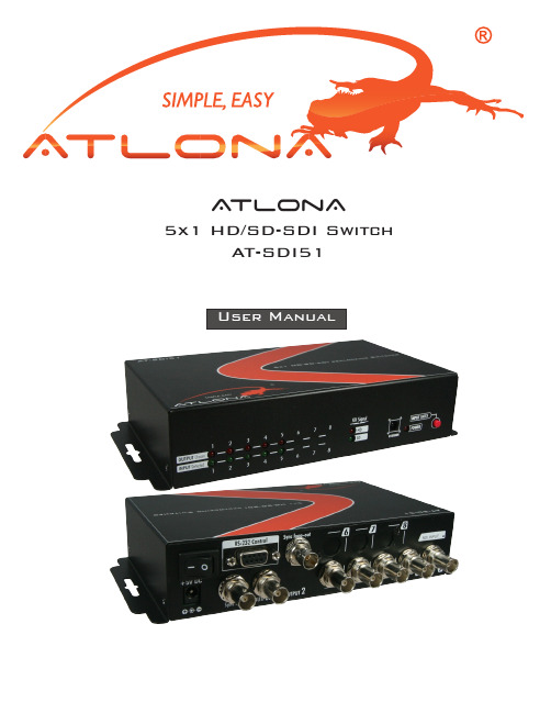
A tlonA5x1 HD/SD-SDI SwitchAT-SDI511. Introduction (1)2. Features (1)3. Specifications & Package Contents (2)4. Panel Descriptions (3)4.1. Front Panel (3)4.2. Rear Panel (3)5. IR Remote Control (4)6. Hardware Installation (4)7. Safety Information (5)8. Warranty (6)9. Atlona Product Registration (7)This AT-SDI51 receives, equalizes, and reclocks* up to 8 SDI inputs, perfectly switches the desired input to SDI equipped monitors or receivers. The switch supports both HD/SD-SDI bit rates, and the re-transmitted quality is guaranteed. Through RS-232, IR remote, or front panel push button, the control of the SDI switch becomes versatile and easier. AT-SDI51 offers the most convenient and cost effective means for swift switch and duplication of high quality SDI in the market.• HD/SD-SDI Switch• Up to 5 equalized & re-timing SDI inputs*• Dual Color LED indication of HD/SD of the output SDI • Automatic detection of the SDI Input• Synchronizes input/output (switch after vertical sync)• Provides the equalized and reclocked* transmission path up to 300m (1000ft) at SD-SDI or 150m (500ft) at HD-SDI• Multiple control by RS-232, IR remote, and push button*Optional upon requestHD/SD SDI SourceMax. 5 inputsSDI CableHD/SD SDI SourceMax. 5 inputsHD/SD SDI LCDFront Panel1. Chosen input channel LED2. Input channel auto detection LED3. Output HD/SD detection LED4. IR remote receiver5. Power indicator LED6. Push button for input channel switchRear Panel7. Power switch8. 5V DC power jack9. Synchronized SDI signal input10. RS-232 control port for PC control 11. SDI output12. Synchronized signal loop-out (add 75Ω terminator if not connect) 13. SDI inputIReservedTo the rightChannel 5ReservedChannel 1Channel 6ReservedChannel 2Channel 7ReservedChannel 3Channel 8To the leftChannel 41. Connect SDI enable equipments to the output of AT-SDI51.2. Connect the SDI input sources to the inputs of AT-SDI51.3. Plug power adapter cable into 5V DC power jack.4. Use IR remote, RS-232, or front panel push button to switch between input channels.HD/SDHD/SD SDI Recorder HD/SD SDI CameraRS232 control portSafeguardsTo reduce the risk of electric shock, do not expose this product to rain or moisture.If the wall plug does not fit into your local power socket, hire an electrician to replace your obsolete socket.Do not modify the wall plug.Doing so will void the warranty and safety features.This equipment should be installed near the socket outlet and the device shouldbe easily accessible in case it requires disconnection.PrecautionsFCC Regulations state that any unauthorized changes or modifications to this equipment not expressly approved by the manufacturer could void theuser’s authority to operate this equipment.Operate this product using only the included external power supply. Use of other power supplies could impair performance, damage the product or cause fires.In the event of an electrostatic discharge, this device may automatically turn off. If this occurs, unplug the device, and plug it back in.Protect and route power cords so they will not be stepped on or pinched by anything placed on or against them. Be especially careful of plug-ins, or cord exit points from this product. Avoid excessive humidity, sudden temperature changes or temperature extremes.Keep this product away from wet locations such as bathtubs, sinks, laundries, wet basements and swimming pools.Use only accessories recommended by ATLONA to avoid fire, shock or other hazards.Unplug the product before cleaning. Usea damp cloth for cleaning. Do not use cleaning fluid or aerosols, which could enter the unit and cause damage, fire or electrical shock. Some substances may also mar the finish of the product.Never open or remove unit panels or make any adjustments not described in this manual. Attempting to do so could expose you to dangerous electrical shock or other hazards. It may also cause damage to your AT-SDI51. Opening the product will void the warranty.Do not attempt to service the unit. Instead disconnect it and contact your Authorized ATLONA reseller or contact ATLONA directly.1. LIMITED WARRANTYAtlona Technologies warrants that (a) its products (the “Product”) will perform substantially in accordance with the accompanying written materials for a period of 3 YEARS from the date of receipt and (b) that the Product will be free from defects in materials and workmanship under normal use and service for a period of 3 years. In the event applicable law imposes any implied warranties, the implied warranty period is limited to 3 years from the date of receipt. Some jurisdictions do not allow such limitations on duration of an implied warranty, so the above limitation may not apply to Customer.2. CUSTOMER REMEDIESAtlona Technologies and its suppliers’ entire liability and Customer’s exclusive remedy shall be, at Atlona Technolo-gies’ option, either return of the price paid for the Product, or repair or replacement of the Product that does not meet this Limited Warranty and which is returned to Atlona Technologies with a copy of Customer’s receipt. This Limited Warranty is void if failure of the Product has resulted from accident, abuse, or misapplication. Any replacement Prod-uct will be warranted for the remainder of the original warranty period or 3 year, whichever is longer.3. NO OTHER WARRANTIESTO THE MAXIMUM EXTENT PERMITTED BY APPLICABLE LAW, ATLONA TECHNOLOGIES AND ITS SUPPLI-ERS DISCLAIM ALL OTHER WARRANTIES, EITHER EXPRESS OR IMPLIED, INCLUDING, BUT NOT LIMITED TO IMPLIED WARRANTIES OF MERCHANTABILITY AND FITNESS FOR A PARTICULAR PURPOSE, WITH REGARD TO THE PRODUCT AND ANY RELATED WRITTEN MATERIALS. THIS LIMITED WARRANTY GIVES CUSTOMER SPECIFIC LEGAL RIGHTS. CUSTOMER MAY HAVE OTHER RIGHTS DEPENDING ON THE JU-RISDICTION.4. NO LIABILITY FOR DAMAGESTO THE MAXIMUM EXTENT PERMITTED BY APPLICABLE LAW, IN NO EVENT SHALL ATLONA TECHNOLO-GIES OR ITS SUPPLIERS BE LIABLE FOR ANY DAMAGES WHATSOEVER (INCLUDING WITHOUT LIMITA-TION, SPECIAL, INCIDENTAL, CONSEQUENTIAL, OR INDIRECT DAMAGES FOR PERSONAL INJURY, LOSS OF BUSINESS PROFITS, BUSINESS INTERRUPTION, LOSS OF BUSINESS INFORMATION, OR ANY OTHER PECUNIARY LOSS) ARISING OUT OF THE USE OF OR INABILITY TO USE THIS PRODUCT, EVEN IF ATLONA TECHNOLOGIES HAS BEEN ADVISED OF THE POSSIBILITY OF SUCH DAMAGES. IN ANY CASE, ATLONA TECHNOLOGIES’ AND ITS SUPPLIERS’ ENTIRE LIABILITY UNDER ANY PROVISION OF THIS AGREEMENT SHALL BE LIMITED TO THE AMOUNT ACTUALLY PAID BY YOU FOR THE PRODUCT. BECAUSE SOME JU-RISDICTIONS DO NOT ALLOW THE EXCLUSION OR LIMITATION OF LIABILITY FOR CONSEQUENTIAL OR INCIDENTAL DAMAGES, THE ABOVE LIMITATION MAY NOT APPLY TO YOU.ATLONA2151 O’toole Ave, Ste DSan Jose CA 95131Toll Free: 1-877-536-3976International: 408-954-8782FAX: 408-954-8792Website: E-MAIL:***************Thank you for purchasing this Atlona product — we hope you’ll enjoy it.We also hope that you’ll take a few moments to register your new purchase. Registration creates an ownership record if your product is lost or stolen and helps ensure you’ll receive notification of performance issues and firm-ware updates.At Atlona, we respect and protect your privacy and assure you that your registration information is completely secure. Of course, Atlona product registration is totally voluntary and failure to register will not diminish your limited warranty rights.To register go to /registration。
(V2.3)SDI5209_5219_5220_Datasheet_May28_14

FLASH_DATA FLASH_ADDL *** SGADCON WDCON SGADCON2 SBUF EXIF TMOD SP 1 *** SGADC3 WD_TA * PD_CON PWMF_H P0M1 TL0 DPL 2
FLASH_ENA * FLASH_ENB * *** SGADC1 SARDATA PWM0 P1M1 TH0 DPL(1) 4 *** *** PWM1 P1M1 TH1 DPH(1) 5
芯易德科技(深圳)有限公司
SOLIDIC
数据手册
SDI5209/5219/520
SDI5209/SDI5219/SDI5220系列
V2.3
本次更新: 1: Flash 操 作 说 明 ( 操 作 前 , 最 好 清 除 安 全 状 态 , 请 注 意 最 新 的 样 例 代 码 ) 2: 在 配 置 PCON进 入 休 眠 前 , 最 好 加 一 条 空 指 令 “ NOP” 。 3: 在 采 用 “ STOP1/2 进 入 指 令 ” 的 程 序 中 , 最 好 将 “ 非 唤 醒 中 断 ” 优 先 级 设 置 为 低 ( 复 位 默 认 ) , 用 作 唤 醒 的 中 断 设 置 为 高 优 先 级 ! ! ( 10.4 MCU 工 作 模 式 )
Bit‐1 P11 Bit‐1 P1M01 Bit‐1 P1M11
Bit0 P10 Bit0 P1M00 Bit0 P1M10
P2口:默认配置“标准51输出模式”
P2(0xA0): P2 口数据寄存器 (默认值:0xFF) Bit‐7 Bit‐6 Bit‐5 Bit‐4 Bit‐3 Bit‐2 P25 P24 P23 P22 P2M0(0x96): P2 口模式配置寄存器 0(默认值:0x00) Bit‐7 Bit‐6 Bit‐5 Bit‐4 Bit‐3 Bit‐2 P2M04 P2M03 P2M02