
机械专业外文文献翻译--论药品包装机械的概念设计
中英文翻译原文:Comment on medicines and chemical reagents package machineryconceptual designIn recent years, Carry out GMP (medicines and chemical reagents produces specifications of quality) attestation system because of sustained our country economic situation rise and country to pharmacy industry mandatory. Medicines and chemical reagents package machinery has got quite great progress. The new product increases by gradually. Engineering level has had very big improvement. But be returning very big gaps back to existence compared with international standards. Level being close to 60%'s product cannot to reach upper developed country century eighties. Large-scale advanced equipment is dependent on entrance mainly. Low our country medicines and chemical reagents package machinery engineering level is that the design designing personnel low level from our country enterprise arouses to a great extent.One, our country medicines and chemical reagents package machinery current situation analysesOur country medicines and chemical reagents package machinery still has bigger gap compared with advanced international level. What time is insufficient on domestic medicines and chemical reagents package machinery design under main existence1) Backward domestic mechanical performance medicines and chemical reagents package machinery mostly, accuracy low velocity, is slow, stationarity dispatches package machinery travel process to contain large amount of dyadic complicated intermittence motion. Come to come true mainly from the cam, the connecting rod. But, many design that the personnel is unable to require that the independence designs the parameter calculating cam bar linkage kinematics and dynamics according to job cycle picture and accuracy. Be only the surveying and mapping carrying out a piecemeal that the abroad model machine cam connecting rod part is dismantled down simplely. Bring about actuating mechanism error is very big. That domestic medicines and chemical reagents package machinery runs speed mostly is more general than hanging down according to cutting frequency if the aluminium moulds bubble coverpacker's for 100 one 300 mins, full-automatic medicine box packer dress box speed 50- 200 boxes/ ms in. But, on the international, the advanced aluminium moulds rushing steeping cover packer cutting frequency be able to reach 600 mins. Full-automatic medicine box packer dress box speed is able to reach 600 ~ 800 box/ mins. Not only working speed of domestic medicines and chemical reagents package machinery is slow. And, the partner has bigger noise.2) Is under the control of horizontal backward. Domestic medicines and chemical reagents package machinery controls low, automation of level difference mostly , the malfunction leads height. (Main package machinery finger box dress controls domestic medicines and chemical reagents with drinking wine holding machinery with) adopt PLC to do a scene mostly. But, advanced medicines and chemical reagents package machinery realizes supervisory control abroad mostly from computer system. Under the control of horizontal relatively backward. Great majority domestic medicines and chemical reagents package machinery automation sex is relatively poor. Adopt a single to produce a pattern first commonly. The full-automatic production line is few. Two is that full-automation works cannot to achieve. Require that the manpower feeds in raw material. Hand movement enchases. If in a little paper box packer, Page, paper box all needs medicine board , specifications paper to move charging personally. And require specially-assigned person to pay attention to if specifications, medicine board, paper box already finish using at any time. Happen to avoid bringing about machine racing or bringing about incomplete specifications, medicine board, and medicine box phenomenon. Other, domestic medicines and chemical reagents package mechanic failure rates are higher. Control a component (if the relay, electromagnetic valve, contactor, breaker etc.) etc. are often easy to damage. Halt also to frequently occur the malfunction.3) Functions are unitary, expansion sex is bad. Medicines and chemical reagents package machinery is that the form designs that specifically for specially appointed package. The general specification range inner in regulation is adjustable. But, a lot of our country medicines and chemical reagents package machinery considers insufficiency when designing that. Be not that reforming going a step further sets apart sufficient space. Cause the machinery designing that to be able to only adapt to the form board in several kinds simplicities. Change not adapting to wrapping material or the form board dimension. Fit in with even. The package finished product mass giving birth to a child is neither nice.4) Considers deficiency synthetically. Resource does not fully utilize. Our country medicines and chemical reagents there exists the chaos phenomenon in package machinery design. A lot of machinery designs that the personnel drags to the electric motor moving the synchrony technology, the servo drive technology do not knows. The problem simple electrical equipment available is resolved uses complicated mechanism to come to come true but. Some though the control organ works to come having adopt the synchrony electric motor to wait for a device. But choose block of wood ding-dang. The maximum having brought about resource not only wastes this condition. And make machinery function designing that low.5) Model is inflexible. Model seldom considering machinery time medicines and chemical reagents of our country package machinery design. Many machine molding that the manufacturer produces is not beautiful do not have model even. Give person feeling to rigid, to inflexible, not to have vigor. A few medicine box packers are middle. The nut all assembles screw on the machine outside board. But, the oil cup and flow nipple that a little lubrication uses also can be seen everywhere. Be stained fully with a greasy dirt easy to use machine everywhere time oiling. Impression is rough to person. No beautiful.Two, medicines and chemical reagents package machinery conceptual design contentPeople long-term study passes. Define conceptual design being: "Have been ascertaining the mission queen. Pass abstract-relation. Design the function structure. Explore appropriate effect principle and their combination waiting. Ascertain out basic finding the solution approach. Reach find the solution scheme. This part of the conceptual design designing that the job is called conceptual design is referred to make the queen who designs purpose and now has condition clear. The designer searches for many-sided knowledge. Analysis abstracts the solution on generating dyadic broad frame significance the day after tomorrow. Medicines and chemical reagents package machinery conceptual design demands according to each product life cycle stages. Carrying out the product function creates , the function breaks up as well as the function and son are functional physical design: That conception and systematization carrying out the scheme satisfying the operating principle that the function and structure demand finding the solution and carrying out the operating principle carrier realizing the function structure's design the conceptual design process is that one finds the solution realizing a function's , satisfies the various technologyand various there existing in economic target's , possibility scheme well ultimate for sure synthetically optimum scheme process. The conceptual design effect embodies in the product design early phase stage mainly. Chief architect is based on functional need of product but primitive conception and impulsion sprouting out form the product main body frame. And, it responds to every main module and module including. In order to accomplishing overall layout and the exterior, the first step designs that. And then carry out the optimization appraising a sum. Ascertain the overall design plan. Design that the personnel carries out the chief architect design thought going to designing middle concretely again from every part. Detail designs realization. The conceptual design putting medicines and chemical reagents package machinery into practice demands to design that the personnel reinforces the cognition to medicines and chemical reagents package first. Deepen the connotation understanding medicines and chemical reagents packages. Introduce modern package idea. Be in line with the international conventions actively. Modern package is to ensure the product safety not only. Make product transportation convenient. And be getting up propagate, environmental protection, defends against false. Attractive looks waits for the many-sided effect. Wrap up contents additional information. The medicines and chemical reagents package machinery design personnel should show solicitude for development of package system closely. Go deep into the handicraft studying package. Know demand of development of wrapping material and the person to machinery product very well. Only when such ability designs that out satisfy the high tone machinery product that the consumer demands. Medicines and chemical reagents package machinery conceptual design content has mainly:1) Makes the design mission clear. Be ready for feasibility analysis. The designer designs initial stage working in being in progress. Respond to the feasibility considering a product sufficiently. One aspect is the marketplace thinking. Include the production marketing, product raw material, the fabricating cost thinking: Another aspect is thinking that the product processes. Include thinking now having a working ability, processing handicraft, processing the function and periphery supporting industry. Periphery supporting environment thinking points to the local enterprise working ability mainly processes level, heat treatment handicraft and the infrastructural facilities construction etc.2) Function design. Great majority our country medicines and chemical reagents package machinery is the same kind model copying to abroad. But peculiar nationalconditions because of our country existence. Must carry out appropriate reforming on the product. To satisfy request of our country. But fault blindly copy blindly. The machinery designing that is packed in, irrigates the dress function outside except needing to satisfy a box. We must consider the additional function packing machinery. If in package box should add a counting cup. The medicine spoon waits an utensil down. Be put into use with convenience of customers. In machine, kind of aspect developing can design comparatively advanced machinery. If sterile pack machinery, the package machinery retaining freshness etc.Can develop the corollary equipment selling complete sets of equipment and the post-processing at reduced prices in the medicines and chemical reagents package front.3) Functions decomposition. Medicines and chemical reagents package machinery belongs to the integration of machinery with electronics product. Should consider every function all round time design. Sort Er Yan. The medicines and chemical reagents package machinery function may divide 3 major parts being that organization moves, monitors biography feel, the information processing and controlling a function basically. The function subdivides organization motion according to may not kind with machine , packer may be molding , heat-seal , pressure trace mark, according to cutting 4 big functions if the aluminum moulds bubble cover. But, paper box package machinery may be that the box opens, paper box transfers, breaks tongue , functions such as inserting tongue , flattening and putting a batch number up mark poison board under paper folding, deducing paper feed. Want to consider machinery lubrication, safe functions such as running, packing hygiene of machinery too in the process of design. This demands the technology designing that the personnel considers detecting sufficiently. Brightness, machine, electricity integration technology, computer art. Intersection between the pneumatic technology, the logistics technology connection.4) Organization is designed. Be to realize the predetermined function. We need to use different organization. This needs the part synthesizing each considering a complete machine among one process. Use the product designing that while satisfying the usage request. Structure is simple, pragmatic. Medicines and chemical reagents package machinery organization designs time. Respond to the principle choosing appropriate organization motion and constituting. Think sufficiently to realize what specially appointed motion needs organization. If cam organization. Bar linkage. Cam bar linkage. Respond to the technology wielding separation drive at the same time.Think that the transmission shaft designs a problem (if castellated shaft and ladder axis etc.) and drive are systematic synthetically. Design that process middle should cut down the effect that the uncertainty factor brings about to the full. Messenger organization operation is stable. Design that machinery carries out kinetic methods of analysis answering now and then. With lifting, machinery runs speed and stationarity. Should think that various packing machinery, adjustable, holds the mistake, but expansion, stationarity as well as beautiful-rization besides. Run after machinery is deft but stable. Design process but consult package machinery design of all kinds strong point. Draw other machinery (if plastic machinery, prints machinery) merit at the same time. Design the outside except carrying out organization. Return approach back to the realization should think that every function is other. If vacuum, electrical equipment waits under the control of. To expect that optimum combination is a product's turn.5) System under the control of schemes design. In medicines and chemical reagents package machinery, a very important part is that real time detecting is back-off to every organization. To ensure that equipment operation is smooth. Now many machinery products has selected and used large amount of photo electricity switch being the detecting component. Equipment has such as PC detecting bubble cover system on some machinery and the like system. This need all designs that meticulously. And, the general naval company is an integral whole.Three, concluding remarksThe thought a concept is designed melts to enter medicines and chemical reagents package machinery design being able to fall off designing a fault. Shorten a design cycle. Accelerate the product exploitation. Make the product designing that more rational, have affinity, more suitable man-machine project more. It is also that the main means costing down and improving enterprise competition is short of passive competition aspect backward for improving medicines and chemical reagents package machinery design at the same time. To adapt to the challenge that "queen GMP times" brings about. Design that the personnel must take product conceptual design seriously. Deepen the significance understanding conceptual design's.译文论药品包装机械的概念设计近年来,由于我国经济形势的持续高涨和国家对制药行业强制性推行GMP(药品生产质量规范)认证制度,药品包装机械取得了长足的进步。
论药品包装机械的概念设计外文文献翻译、外文翻译、中英文翻译
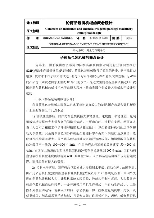
译文标题论药品包装机械的概念设计原文标题Comment on medicines and chemical reagents package machineryconceptual design作者BRIAN HUGH W ARNER译名布莱恩·休·沃纳国籍美国原文出处JOURNAL OF DYNAMIC SYSTEMS MEASUREMENT& CONTROL动力系统,测量与控制杂志论药品包装机械的概念设计近年来,由于我国经济形势的持续高涨和国家对制药行业强制性推行GMP(药品生产质量规范)认证制度,药品包装机械取得了长足的进步。
新产品日益增多,技术水平有了很大的改进。
但与国际水平相比还存在着很大的差距,近60%的产品达不到发达国家上世纪80年代的水平,先进大型的设备主要依赖进口。
我国药品包装机械的低技术水平在很大程度上是由我国企业设计人员低水平设计引起的。
一、我国药品包装机械现状分析我国药品包装机械与国际先进水平相比尚有较大的差距.国产药品包装机械设计上主要存在以下几点不足:1) 机械性能落后,国产药品包装机械大多精度低、速度慢、平稳性差。
包装机械运转过程包含大量复杂的间歇式运动,主要由凸轮、连杆来实现。
然而许多设计人员不会根据工作循环图和精度要求独立设计计算凸轮连杆机构的运动学和动力学参数,只是简单的把国外样机的凸轮连杆零件拆卸下来进行逐点测绘,造成执行机构误差很大。
国产药品包装机械大多运行速度较低,如铝塑泡罩包装机的冲裁频率一般为100~300个/min,全自动药盒包装机的装盒速度50~200盒/min,而国际上先进的铝塑泡罩包装机的冲裁频率能够达到600个/min,全自动药盒包装机的装盒速度能够达到600~ 800盒/min。
国产药品包装机械不仅运行速度慢,而且还伴有较大的噪音。
2) 控制水平落后。
国产药品包装机械大多控制水平低、自动性差、故障率高。
国产药品包装机械(主要指盒装和灌装机械)大多采用PLC作现场控制,而国外先进的药品包装机械大多由计算机系统实现监控,控制水平相对落后。
机械外文翻译文献翻译包装机械的发展

中文译文包装机械的发展包装是必要的产品进入流通领域,包装是主要的手段,包装机械包装是产品进入流通领域的必要条件,而实现包装的主要手段是包装机械。
简单来说,包装机就是把产品包装起来的机器,起着保护,美观的作用。
包装机主要分为两个方面,一是流水线式的整体生产包装,二是产品外围包装设备随着时代的发展,科技的进步,包装机械在包装领域中正起着越来越大的作用。
我国包装机行业起步于20世纪70年代,在80年代末和90代中期的到了迅速发展。
已经成为机械行业中的10大行业之一,无论产量,还是品种上,都取得了令人瞩目的成就,为我我国的包装工业的快速发张提供了有力的保障目前。
目前,我国已成为世界包装机械工业生产和消费十大国之一。
新型包装机往往是机、电、气、一体化的设备.充分利用信息产品的最新成果,采用气动执行机构、伺服电机驱动等分离传动技术,可使整机的传动链大大缩短,结构大为化简,工作精度和速度大大提高。
机电一体化的实质就是从系统观点出发,运用过程控制原理,将机械、电子与信息、检测等有关技术进行有机组合,实现整体最佳化。
21世纪包装机发展趋势1.高生产率。
包装机的生产效率已经从每分钟数件发展到数10件,热成型-充填-封口机的生产率可达500件每分钟以上。
2.自动化。
3.单机多功能。
在单机上实现多功能,可方便地扩大使用范围,代表性的是德国BOSCH 公司所属的HESSER厂生产的心轴轮多工位制袋真空包装,其制袋、称重、充填、抽真空、封口等多功能可在一台单机上完成。
4.组成生产线。
当需要的功能越来越多是,将所有的功能集中在一个单机上结构非常复杂,这是可以把功能不同、效率相比配的几种机器组合成功铰齐全的生产线上。
外国包装机的发展现状:德国:德国的包装机械在计量、制造、技术性能方面均属于世界一流。
该国生产的啤酒、饮料灌装成套设备生产速率快、自动化程度高、可靠性好。
主要体现在:工艺流程的自动化、生产效率高,满足了交货期短和降低工艺流程成本的要求;设备具有更高的柔性和灵活性。
打包机论文中英文对照资料外文翻译文献
中英文对照资料外文翻译文献打包机打包机是一种农业机械,它用于压缩已切割和倾斜的作物(如草、稻草或青贮饲料)成易于处理、运输和储存的小包。
常用的打包机有几个不同类型,分别生产不同类型的包-矩形的、圆柱形的,大小各不相同,用麻绳、网或金属丝缠绕起来。
工业打包机还可以用在材料回收设备上,主要用于包装需要运输的金属、塑料或纸。
圆形打包机在工业化国家最常用的打包机是这种又大又圆的打包机。
它生产圆柱状的“圆”或“筒状”的包。
草在打包机内被捲起,使用橡胶带、固定滚筒,或两者的组合。
当包达到规定尺寸时,用网或麻绳裹住它,以保持其固有的形状。
打包机的后面打开,包被排出。
包在这个阶段完成,但也可以用塑料薄膜包裹,当在室外储存时能保持干草的干燥或者将潮湿的草变成青贮饲料。
可变仓打包机通常生产直径为48至72英寸(120~ 180厘米)、宽达60英寸(150厘米)的包。
无论在任何地区,这些包可以重达1100至2200磅(500-1000公斤),包的重量取决于大小,材料,和水分含量。
最初,圆形打包机的构思由Ummo Luebbens于大约1910年提出,第一台圆形打包机才生产出来,一直到1947年Allis-Chalmers 引进了旋转打包机之后。
由于它的干草包脱水干燥和重量轻的特点从而得以推向市场,到1960年生产结束时,AC已经销售了近70000台接下来的一个重大创新是在1972年,当时Vermeer公司开始出售其型号为605的第一台现代圆形打包机。
以前,圆的干草包仅仅是干草缚在一起的肿块,但Vermeer设计使用皮带将干草紧密结合起来形成一个圆柱体,正如今天所看到的样子。
大型矩形打包机另一种常用类型的打包机生产大型的矩形包,每个包缠绕半打左右的麻绳,然后再打结。
这样的包非常紧凑,重量又普遍比圆形的包大几分。
在加拿大的草原,它们被称为草原猛禽。
小型矩形打包机这种打包机现今是不常见的,但在许多国家却是相当流行,如新西兰和澳大利亚,除了大型包的生产,还生产小型矩形 (通常被称为“正方形的”) 包。
机械类外文文献及翻译
机械类外文文献及翻译(文档含中英文对照即英文原文和中文翻译)原文:GEAR AND SHAFT INTRODUCTIONAbstract:The important position of the wheel gear and shaft can't falter in traditional machine and modern machines.The wheel gear and shafts mainly install the direction that delivers the dint at the principal axis box. The passing to process to make them can is divided into many model numbers, using for many situations respectively. So we must be the multilayers to the understanding of the wheel gear and shaft in many ways .Key words: Wheel gear; ShaftIn the force analysis of spur gears, the forces are assumed to act in a single plane. We shall study gears in which the forces have three dimensions. The reason for this, in the case of helical gears, is that the teeth are not parallel to the axis of rotation. And in the case ofbevel gears, the rotational axes are not parallel to each other. There are also other reasons, as we shall learn.Helical gears are used to transmit motion between parallel shafts. The helix angle is the same on each gear, but one gear must have a right-hand helix and the other a left-hand helix. The shape of the tooth is an involute helicoid. If a piece of paper cut in the shape of a parallelogram is wrapped around a cylinder, the angular edge of the paper becomes a helix. If we unwind this paper, each point on the angular edge generates an involute curve. The surface obtained when every point on the edge generates an involute is called an involute helicoid.The initial contact of spur-gear teeth is a line extending all the way across the face of the tooth. The initial contact of helical gear teeth is a point, which changes into a line as the teeth come into more engagement. In spur gears the line of contact is parallel to the axis of the rotation; in helical gears, the line is diagonal across the face of the tooth. It is this gradual of the teeth and the smooth transfer of load from one tooth to another, which give helical gears the ability to transmit heavy loads at high speeds. Helical gears subject the shaft bearings to both radial and thrust loads. When the thrust loads become high or are objectionable for other reasons, it may be desirable to use double helical gears. A double helical gear (herringbone) is equivalent to two helical gears of opposite hand, mounted side by side on the same shaft. They develop opposite thrust reactions and thus cancel out the thrust load. When two or more single helical gears are mounted on the same shaft, the hand of the gears should be selected so as to produce the minimum thrust load.Crossed-helical, or spiral, gears are those in which the shaft centerlines are neither parallel nor intersecting. The teeth of crossed-helical fears have point contact with each other, which changes to line contact as the gears wear in. For this reason they will carry out very small loads and are mainly for instrumental applications, and are definitely not recommended for use in the transmission of power. There is on difference between a crossed heli : cal gear and a helical gear until they are mounted in mesh with each other. They are manufactured in the same way. A pair of meshed crossed helical gears usually have the same hand; that is ,a right-hand driver goes with a right-hand driven. In the design of crossed-helical gears, the minimum sliding velocity is obtained when the helix angle areequal. However, when the helix angle are not equal, the gear with the larger helix angle should be used as the driver if both gears have the same hand.Worm gears are similar to crossed helical gears. The pinion or worm has a small number of teeth, usually one to four, and since they completely wrap around the pitch cylinder they are called threads. Its mating gear is called a worm gear, which is not a true helical gear. A worm and worm gear are used to provide a high angular-velocity reduction between nonintersecting shafts which are usually at right angle. The worm gear is not a helical gear because its face is made concave to fit the curvature of the worm in order to provide line contact instead of point contact. However, a disadvantage of worm gearing is the high sliding velocities across the teeth, the same as with crossed helical gears.Worm gearing are either single or double enveloping. A single-enveloping gearing is onein which the gear wraps around or partially encloses the worm.. A gearing in which each element partially encloses the other is, of course, a double-enveloping worm gearing. The important difference between the two is that area contact exists between the teeth of double-enveloping gears while only line contact between those of single-enveloping gears. The worm and worm gear of a set have the same hand of helix as for crossed helical gears, but the helix angles are usually quite different. The helix angle on the worm is generally quite large, and that on the gear very small. Because of this, it is usual to specify the lead angle on the worm, which is the complement of the worm helix angle, and the helix angle on the gear; the two angles are equal for a 0-deg. Shaft angle.When gears are to be used to transmit motion between intersecting shaft, some of bevel gear is required. Although bevel gear are usually made for a shaft angle of 0 deg. They may be produced for almost any shaft angle. The teeth may be cast, milled, or generated. Only the generated teeth may be classed as accurate. In a typical bevel gear mounting, one of the gear is often mounted outboard of the bearing. This means that shaft deflection can be more pronounced and have a greater effect on the contact of teeth. Another difficulty, which occurs in predicting the stress in bevel-gear teeth, is the fact the teeth are tapered.Straight bevel gears are easy to design and simple to manufacture and give very good results in service if they are mounted accurately and positively. As in the case of squr gears, however, they become noisy at higher values of the pitch-line velocity. In these cases it is often go : od design practice to go to the spiral bevel gear, which is the bevel counterpart of thehelical gear. As in the case of helical gears, spiral bevel gears give a much smoother tooth action than straight bevel gears, and hence are useful where high speed are encountered.It is frequently desirable, as in the case of automotive differential applications, to have gearing similar to bevel gears but with the shaft offset. Such gears are called hypoid gears because their pitch surfaces are hyperboloids of revolution. The tooth action between such gears is a combination of rolling and sliding along a straight line and has much in common with that of worm gears.A shaft is a rotating or stationary member, usually of circular cross section, having mounted upon it such elementsas gears, pulleys, flywheels, cranks, sprockets, and other power-transmission elements. Shaft may be subjected to bending, tension, compression, or torsional loads, acting singly or in combination with one another. When they are combined, one may expect to find both static and fatigue strength to be important design considerations, since a single shaft may be subjected to static stresses, completely reversed, and repeated stresses, all acting at the same time.The word “shaft” covers numerous v ariations, such as axles and spindles. Anaxle is a shaft, wither stationary or rotating, nor subjected to torsion load. A shirt rotating shaft is often called a spindle.When either the lateral or the torsional deflection of a shaft must be held to close limits, the shaft must be sized on the basis of deflection before analyzing the stresses. The reason for this is that, if the shaft is made stiff enough so that the deflection is not too large, it is probable that the resulting stresses will be safe. But by no means should the designer assume that they are safe; it is almost always necessary to calculate them so that he knows they are within acceptable limits. Whenever possible, the power-transmission elements, such as gears or pullets, should be located close to the supporting bearings, This reduces the bending moment, and hence the deflection and bending stress.Although the von Mises-Hencky-Goodman method is difficult to use in design of shaft, it probably comes closest to predicting actual failure. Thus it is a good way of checking a shaft that has already been designed or of discovering why a particular shaft has failed in service. Furthermore, there are a considerable number of shaft-design problems in which the dimension are pretty well limited by other considerations, such as rigidity, and it is only necessary for the designer to discover something about the fillet sizes, heat-treatment,and surface finish and whether or not shot peening is necessary in order to achieve the required life and reliability.Because of the similarity of their functions, clutches and brakes are treated together. In a simplified dynamic representation of a friction clutch, or brake, two in : ertias I and I traveling at the respective angular velocities W and W, one of which may be zero in the case of brake, are to be brought to the same speed by engaging the clutch or brake. Slippage occurs because the two elements are running at different speeds and energy is dissipated during actuation, resulting in a temperature rise. In analyzing the performance of these devices we shall be interested in the actuating force, the torque transmitted, the energy loss and the temperature rise. The torque transmitted is related to the actuating force, the coefficient of friction, and the geometry of the clutch or brake. This is problem in static, which will have to be studied separately for eath geometric configuration. However, temperature rise is related to energy loss and can be studied without regard to the type of brake or clutch because the geometry of interest is the heat-dissipating surfaces. The various types of clutches and brakes may be classified as fllows:. Rim type with internally expanding shoes. Rim type with externally contracting shoes. Band type. Disk or axial type. Cone type. Miscellaneous typeThe analysis of all type of friction clutches and brakes use the same general procedure. The following step are necessary:. Assume or determine the distribution of pressure on the frictional surfaces.. Find a relation between the maximum pressure and the pressure at any point. Apply the condition of statical equilibrium to find (a) the actuating force, (b) the torque, and (c) the support reactions.Miscellaneous clutches include several types, such as the positive-contact clutches, overload-release clutches, overrunning clutches, magnetic fluid clutches, and others.A positive-contact clutch consists of a shift lever and two jaws. The greatest differences between the various types of positive clutches are concerned with the design of the jaws. To provide a longer period of time for shift action during engagement, the jaws may be ratchet-shaped, or gear-tooth-shaped. Sometimes a great many teeth or jaws are used, and they may be cut either circumferentially, so that they engage by cylindrical mating, or on the faces of the mating elements.Although positive clutches are not used to the extent of the frictional-contact type, they do have important applications where synchronous operation is required.Devices such as linear drives or motor-operated screw drivers must run to definite limit and then come to a stop. An overload-release type of clutch is required for these applications. These clutches are usually spring-loaded so as to release at a predetermined toque. The clicking sound which is heard when the overload point is reached is considered to be a desirable signal.An overrunning clutch or coupling permits the driven member of a machine to “freewheel” or “overrun” bec ause the driver is stopped or because another source of power increase the speed of the driven. This : type of clutch usually uses rollers or balls mounted between an outer sleeve and an inner member having flats machined around the periphery. Driving action is obtained by wedging the rollers between the sleeve and the flats. The clutch is therefore equivalent to a pawl and ratchet with an infinite number of teeth.Magnetic fluid clutch or brake is a relatively new development which has two parallel magnetic plates. Between these plates is a lubricated magnetic powder mixture. An electromagnetic coil is inserted somewhere in the magnetic circuit. By varying the excitation to this coil, the shearing strength of the magnetic fluid mixture may be accurately controlled. Thus any condition from a full slip to a frozen lockup may be obtained.齿轮和轴的介绍摘要:在传统机械和现代机械中齿轮和轴的重要地位是不可动摇的。
机械设计类英文文献及翻译

The Sunflower Seed Huller and Oil PressBy Jeff Cox-- from Organic Gardening, April 1979, Rodale PressIN 2,500 SQUARE FEET, a family of four can grow each year enough sunflower seed to produce three gallons of homemade vegetable oil suitable for salads or cooking and 20 pounds of nutritious, dehulled seed -- with enough broken seeds left over to feed a winter's worth of birds.The problem, heretofore, with sunflower seeds was the difficulty of dehulling them at home, and the lack of a device for expressing oil from the seeds. About six months ago, we decided to change all that. The job was to find out who makes a sunflower seed dehuller or to devise one if none were manufactured. And to either locate a home-scale oilseed press or devise one. No mean task.Our researches took us from North Dakota -- hub of commercial sunflower activity in the nation -- to a search of the files in the U.S. Patent Office, with stops in between. We turned up a lot of big machinery, discovered how difficult it is to buy really pure, unrefined vegetable oils, but found no small-scale equipment to dehull sunflowers or press out their oil. The key to success, however, was on our desk the whole time. In spring 1977, August Kormier had submitted a free-lance article describing how he used a Corona grain mill to dehull his sunflower seeds, and his vacuum cleaner exhaust hose to blow the hulls off the kernels. A second separation floated off the remaining hulls, leaving a clean product. We'd tried it, but because some kernels were cracked and the process involved drying, we hadn't been satisfied. Now we felt the best approach was to begin again with what we learned from Mr. Kormier and refine it.Staff Editor Diana Branch and Home Workplace Editor Jim Eldon worked with a number of hand- and electric-powered grain mills. While the Corona did a passable job, they got the best results with the C.S. Bell #60 hand mill and the Marathon Uni Mill, which is motor-driven. "I couldn't believe my eyes the first time I tried the Marathon," Diana says. "I opened the stones to 1/8th inch, and out came a bin full of whole kernels and hulls split right at the seams. What a thrill that was!"She found that by starting at the widest setting,and gradually narrowing the opening, almost every seed was dehulled. The stones crack the hulls open, then rub them to encourage the seed away from the fibrous lining. The Bell hand mill worked almost as well. "As long as the stones open at least as wide as the widest unhulled seed, any mill will work," she says.Because the seed slips through the mill on its flat side, grading is an important step to take before dehulling. We made three sizing boxes. Thefirst is 1/4-inch hardware cloth [wire screen]. The second is two layers of1/4-inch cloth, moved slightly apart to narrow the opening in one direction, and the third is two layers of screen adjusted to make a still-smaller opening. Since the smallest unhulled seeds are about the size of the largest hulled kernels, the grading step prevents these undersized seeds from passing through unhulled. Processed together at a closer setting, the smallest seeds hulled out.Jim Eldon's workshop is littered with strange-looking pieces of apparatus. They represent initial attempts to build a workable winnowing box, using Kormier's vacuum exhaust idea for a source of air. Jim, Fred Matlack and Diana finally made a box with a Plexiglas front, through which they could observe what was happening.They cut a hole in the back of the box with a sliding cover to regulate the air pressure, and fiddled with various arrangements of baffles. The result was a stream of hulls exiting through one hole while the kernels fell to the bottom of the box. Now they were ready to try a five-pound sample of unhulled sunflower seeds to see how much they could recover.The five pounds were graded and dehulled, then winnowed. We got about one hull for every ten kernels in the final, winnowed product. These are easily picked out. They usually contain kernels still held behind the fibrous strings of the hull. Their weight prevents them from blowing out with the empty hulls. We found that bug-eaten seeds do blow away with the chaff, which was a bonus for cleanliness of the final product. Toss the hulls to the birds, who will find broken seeds among them.Starting with 80 ounces of unhulled seed, we ended up with 41-1/4 ounces of edible whole seeds, 1.8 ounces of damaged seeds suitable for animal feed, and 36.6 ounces of hulls. It took us about an hour. Notbad.Sunflower seeds store perfectly in the hulls, but they deteriorate more rapidly when shelled out. The grain mill dehuller and winnowing box give the gardener a way to have the freshest possible seeds for eating at all times of the year. With the construction of one more piece of equipment -- the oil press -- he can have absolutely fresh, unrefined, polyunsaturated sunflower oil for salads, mayonnaise and cooking.Most light, refined vegetable oils have been extracted using hexane, a form of naphtha. The oil is then heated to boil off the hexane. Lye is dumped into it. It's washed with steam, then heated to remove odors and taste before being laced with preservatives and stabilizers. It may feel oily in the mouth, but you might as well taste air. No so with fresh-made sunflower oil -- it's deliciously yet subtly nutty in flavor, adding unsurpassed flavor to salads.There's good reason to believe that sunflower oil may become the #1 vegetable oil in the U.S. in a few years. It's already #1 in health-conscious Europe. Corn oil has already caught on here for health reasons, and sunflower oil is so much better. Sunflower oil's 70 percent polyunsaturate is just under safflower, with corn oil bringing up the rear with 55 percent. And sunflowers yield 40 percent oil, soybeans only 20 percent.Our oil press isrelatively simple, but it must be welded together. Check the construction directions for details. The press consists of a welded tubular frame which accepts a three-ton hydraulic jack. You may already have one. If not, it can be purchased at most auto and hardware stores for about $16. A metal canister with holes drilled in its sides and one end welded shut holds the mashed sunflower seeds. A piston is inserted in the canister and then inverted and slipped over a pedestal on the frame. The jack is set in place, and the pressure gradually increased over half an hour. The oil drips from the sides of the canister into a tray -- the bottom of a plastic jug slipped over the pedestal works fine -- which empties the oil into a cup. You can filter the oil with a coffee filter to remove pieces of seed and other fine particles that would burn if the oil were used for cooking. If it's for salads or mayonnaise, there's no need to filter it.We first tried using "confectionary" sunflower seeds for oil. These are the regular eating kernels we're used to seeing. They give less than half as much oil as the oilseed types of sunflower. Although you can use confectionary types such as MAMMOTH RUS- SIAN for oil, don't expect to get more than an ounce and a half from a pound of seed. Oilseed produces three or more ounces of oil from a pound of seed and is well worth planting along with confectionary-type seeds. Oilseed has another big advantage -- to prepare it, you can put the whole, unhulled seed into a blender and whiz it until it forms a fine meal, while confectionary seeds must be dehulled first. The entire sequence of grading, dehulling and winnowing is avoided with oilseed.Oil types produce about a tenth of a pound of seed per head in commercial production. Gardeners, with their better soil and care, invariably do better than that. Our conservative estimate is that 1,280 plants will be enough for three gallons of oil. Spaced one foot apart in rows two feet apart, 1,280 oilseed plants will take a space 40-by-56 feet, or 80-by-28 if you want a more rectangular patch to face south.We worked in pound batches, since the canister just holds one pound of mash. After blending, we heated it to 170 degrees F. (77 deg C) by placing it in a 300-degree F. (149 deg C) oven and stirring it every five minutes for 20 minutes. Heating gets the oil flowing and doubles the yield of oil. In case you're wondering,"cold-pressed" oils sold commercially are also heated, and some are subjected to the entire chemical process. The term has no firm meaning within the industry, according to the literature we've surveyed.Heating does not change the structure of fats. It will not turn polyunsaturated fats into saturated fats. In fact, Dr. Donald R. Germann in his book, "TheAnti-Cancer Diet", says that "... an unsaturated fat must be heated to high temperatures -- above 425 degrees F. or 200 degrees C. -- at least 8 or 10 times before any shift toward saturation occurs..." Dean C. Fletcher, Ph.D., of the American Medical Association Department of Foods and Nutrition in Chicago, says, "It's true that either high temperature or repeated heatingdoes change the nature of some of the unsaturated oil molecules. (But) the flavor of the oil changes as these chemical changes occur, spoiling its taste. This effect is probably more profound than any of the physiological changes the altered oil might produce within the body."From 500 gm. of heated mash, we pressed 89 gm. of oil, 89 percent of the entire amount available and twice as much as we could press from unheated oil! The decision is up to you whether or not to heat the mash, but that extra 50 percent seems like an awful lot, especially when the whole technique is so labor intensive. The oil should be stored in the refrigerator, and it's probably best to use it within a month, since it has no preservatives. Mayonnaise made with such fresh oils should be kept refrigerated and used within two weeks. The leftover cake, still containing 50 percent of its oil, is a nutritious addition to your dishes, and makes excellent feed for animals or winter birds. Store the pressed cake in the freezer.We're talking then about a sunflower patch with two kinds of plants -- confectionary such as MAMMOTH RUSSIAN and oilseed such as PEREDOVIK. The oilseed plants should be grown 12 inches apart in rows two feet apart. Four average confectionary heads yield about a pound of unhulled seed. You'll need about 35 pounds of unhulled seed, or 140plants-worth, to yield 20 pounds of hulled kernels, about what a family of four will use in a year. That many plants can be grown in an area 26-by-10 feet. That's 260 square feet. Put that together with the 2,240 square feet for the oilseed sunflowers, and you need a patch about 2,500 square feet -- 25 100-foot rows -- to keep yourself supplied year-round with super nutrition and unsurpassable taste.Winnowing Machine For Sunflower SeedsThe winnowing machine operates on the age-old principle of blowing the chaff away from the heavy grain with a controlled current of air.The unit uses a household or shop-type vacuum cleaner for its air supply. A vacuum cleaner was used as a power source because it can supply a large volume of air over an extended period of time, and most homes and farms have a vacuum cleaner.A cloth bag has been attached to the chaff chute to catch the chaff as it is separated from the seed. The bag allows the hulls to be collected and greatly reduces the amount of waste material normally blown into the air by conventional systems.The unit has been constructed in such a way that the cloth bag and cleaner box can be placed inside the seed box, making a compact package for storage.Tools Required1. Table Saw2. Drill Press3. Band Saw4. Saber SawProcedure (cleaner box)1 . Cut out the two sides of the cleaner box from 1/4-inch plywood.2. Cut out the six interior pieces of the cleaner box from 3/4 x 3-1/2-inch select pine.3. Assemble the cleaner box elements with glue and nails.4. Cut four 1/4-inch square strips of pine four inches long.5. Glue the strips around the end of the chaff chute.6. Sand all surfaces and edges.7. Finish with clear lacquer finish.Procedure (seed box)1. Cut two pieces of pine /34" x 5 /12 x 15 inches for the sides.2. Cut two pieces of pine 3/4 x 5-1/2 x inches for the top and bottom.3. Plow a /14 x 1/4 groove for the front and back panels in all four pieces.4. Rip the top board to 5 inches so that the front panel can slide into the grooves in the side boards.5. Rabbet both ends of each 15-inch side piece to accept the top and bottom boards.6. Drill a hole in the left side board 2-1/2 inches from the top. The size of the hole is determined by the vacuum cleaner hose fitting.7. Cut a 3-1/4 x 4 inch hole in the top 1/2 inch from the right end. This hole will accept the cleaner box.8. Cut two pieces of pine for the baffle.9. Drill two 1-inch holes in the bottom of the baffle box.10. Cut a piece of 1/4 x 8-1/2 x 14 inch plywood for the back panel.11. Cut a 3-inch hole, centered 1-7/8 inches from the top and left sides of the plywood back.12. Assemble the sides, baffles, top, bottom, and back panel with glue and nails.13. Cut an 8-7/16 x 15-3/4-inch piece of Plexiglas for the front.14. Cut a one-inch radius on the top corners of the front.and sand the edges.15. Drill a one-inch thumb hole centered 7/8 inch from the top edge.16. Cut a 3-1/2-inch disk of 1/4-inch plywood for the vent cover.17. Drill a 3/16-inch hole 3/8 inch from the edge of the disk.18. Mount the disk over the vent with a #10 x 1-inch screw.19. Sand all surfaces and edges of the, box.20. Finish with clear lacquer finish.MaterialsCleaner Box2 -- 7-3/4 x 7-1/2 x 3/4" plywood (sides)6 -- 3/4 x 3-1/2 x 24" for all members (baffles)4 -- 1/4 x 1/4 x 4" pine (chute cleats)22 -- 1" x 18 ga. headed nailsWhite vinyl glueClear lacquer finishSeed Box2 -- 3/4' x 5-1/2 x 15" select pine (sides)2 -- 3/4 x 5-1/2 x 8-1/2" select pine (top and bottom)1 -- 3/4 x 3-1/2 x 4-1/2" select pine (baffle)1 -- 3/4 x 4-1/2 x 4-1/2" select pine (baffle)1 -- 1/4 x 8-1/2 x 14" plywood (back)1 -- 1/4 x 3-1/2" dia. plywood (control valve)1 -- 1/4' x 8-7/16 x 15-1/4" Plexiglas (front)1 - #10 x 1" flat head screw18 - 4d finish nailsWhite vinyl glueClear lacquer finish1 -- 17 x 31" cloth laundry bagSunflower Seed Oil PressThe press was designed so that homesteaders can produce sunflower oil from their own seeds. The oil can be pressed as is or heated to 170 degrees F., which doubles oil yield.Both methods require the seed to be ground to fine powder. If you are pressing the oil seed variety, a meat grinder or electric blender will do an excellent job of grinding the seed. The confectionary type of seed will require the seed to be hulled and winnowed before it is ground. A food mill with the stones set at the coarse setting can be used to accomplish this step. The ground kernels are placed in the cylinder with the piston closing the bottom portion of the cylinder.The cylinder is mounted in the press frame and a three-ton hydraulic jack is used to supply the pressure.Because of the great pressures created by the hydraulic jack, it is important that the frame be properly constructed and firmly mounted to the work surface before the pressing operation begins. The following instructions can be given to a welder.Tools Required1. Power Hacksaw2. Metal Band Saw3. Metal Lathe4. Drill Press5. Belt or Disk Grinder6. Arc Welder7. Hand ClampsProcedure (Frame)1. Cut two pieces of 1-3/4" O.D. x 1-3/8" I.D. x 24-1/2 inch long tubing for the uprights.2. Cut one piece of 1-3/4" O.D. x 1-3/8" I.D. x 6-1/2 inch long tubing for the center tube.3. Cut one 3/4" x 2-3/4 x 5-1/2 inch steel bar for the top cross member.4. Cut two pieces of 1-3/4 x 1-3/4 x 8 inch angle iron for the base members.5. Drill two 9/32-inch holes in each base member 1/2 inch from the outer edges.6. Weld the base members, tubes and cross member together as per the drawing.7. Grind all edges to remove any burrs.8. Paint the frame.9. If a mounting board is desired, cut a piece of pine 1-1/4 x 6-1/2 x 12 inches long.10. Center the frame on the board and mark the location of the four mounting holes.11. Drill four 7/8-inch holes 1/4-inch deep to accept the T-nuts.12. Drill four 5/16-inch holes through the mounting board using the same centers created by the 7/8-inch holes.13. Round the edges of the base and sand all surfaces.14. Install four 1/4-20 T-nuts.15. Finish the base with clear lacquer finish.16. Assemble the base to the frame using four 1/4-20 x 1-1/4-inch round head bolts.Procedure (Cylinder)1. Cut a piece of 3-1/2" O.D. x 3-1/4" I.D. tubing 5-3/8 inches long.2. Face both ends on the lathe.3. Cut out a 3-1/2-inch round disk from 1/4-inch plate steel.4. Weld the disk to one end of the tube.5. Drill a series of 3/32-inch holes around the side of the tube on 1/2-inch centers.6. Remove all burrs on the inside and outside of the tube.Procedure (Piston)1. Cut out a 3-3/8-inch disk of 1/4-inch plate steel.2. Cut a 1-3/8" O.D. x 1-1/8" I.D. piece of tubing 1-1/8 inches long.3. Face both ends of the tube.4. Weld the tube in the center of the 3-3/8-inch disk. All welds should be made on the inside of the tube.5. Mount the piston in the lathe and turn the disk to fit the inside diameter of the cylinder. This will be about 3-15/64 inches in diameter.6. Remove any sharp edges.Procedure (Collector Ring)1. Cut the bottom out of a one-gallon plastic bottle. The cut line should be approximately 1-1/2 inches from the bottom of the bottle.2. Make a 1/8 x 1 inch slot at one edge of the bottom outside ring. This will allow the oil to pour into a receiving cup.3. Cut a 1-3/4-inch hole in the center of the bottom, so that the unit will fit over the center tube in the frame.MaterialsFrame2 -- 1-3/4 O.D. x 1-3/8 I.D. x 24-1/2" long H.R.S. (frame tubes)1 -- 1-3/4 O.D. x 1-3/8 I.D. x 6-1/2 inch long H.R.S. (center tube)1 -- 3/4 x 2-3/4 x 5-1/2" flat bar H.R.S. (top cross member)2 -- 1-3/4 x 1-3/4 x 8" angle iron H.R.S. (base members)1 -- 1-1/4 x 6-1/2 x 12" #2 white pine (wood base)4 -- 1/4-20 x 1-1/4 R.H. mounting bolts4 -- 1/4-20 T-nutsBlack enamel for frame (finishing material)Clear lacquer finish for wood base3 -- 1/8" dia. welding rodsCylinder1 -- 1/4 x 3-1/2" dia. C.R.S. disk (top)1 -- 3-1/2 O.D. x 3-1/4 I.D. C.R.S. tube (cylinder)1 -- 1/8 dia. welding rodPiston1 -- 1/4 x 3-3/8 D.A. C.R.S. disk (piston top)1 -- 1-1/4 O.D. x 1 I.D. x 1" long H.R.S. (piston tube)1 -- 1/8 dia. welding rodCollector Ring1 -- Bottom from a one-gallon plastic bottle (oil collector ring)葵花籽脱壳机和油压机由Jeff考克斯-从有机园艺,1979年4月,罗代尔新闻2,500平方尺,一个四口之家每年可以长到足以产生三种葵花籽国产蔬菜沙拉或烹调油和20磅的营养丰富,适合脱皮加仑种子 - 与遗留养活一个冬天的产值,破碎的种子鸟类。
机械外文文献及翻译
与机械相关的外文及翻译Multidisciplinary Design Optimization of Modular Industrial Robots by Utilizing High Level CAD Templates1、IntroductionIn the design of complex and tightly integrated engineering products, it is essential to be able to handle interactions between different subsystems of multidisciplinary nature [1]. To achieve an optimal design, a product must be treated as a complete system instead of developing subsystems independently [2]. MDO has been established as a convincing concurrent design optimization technique in development of such complex products [3,4].Furthermore, it has been pointed out that, regardless of discipline, basically all analyses require information that has to be extracted from a geometry model [5]. Hence, according to Bow-cutt [1], in order to enable integrated design analysis and optimization it is of vital importance to be able to integrate an automated parametric geometry generation system into the design framework. The automated geometry generation is a key enabler for so-called geometry-in-the-loop[6] multidisciplinary design frameworks, where the CAD geometries can serve as framework integrators for other engineering tools.To eliminate noncreative work, methods for creation and automatic generation of HLCt have been suggested by Tarkian [7].The principle of high HLCts is similar to high level primitives(HLP) suggested by La Rocca and van Tooren [8], with the exception that HLCts are created and utilized in a CAD environment.Otherwise, the basics of both HLP and HLCt can, as suggested byLa Rocca, be compared to parametric LEGOV Rblocks containing a set of design and analysis parameters. These are produced and stored in libraries, giving engineers or a computer agent the possibility to first topologically select the templates and then modify the morphology, meaning theshape,of each template parametrically.2、Multidisciplinary Design FrameworkMDO is a “systematic approach to design space exploration”[17], the implementation of which allows the designer to map the interdisciplinary relations that exist in a system. In this work, the MDO framework consists of a geometry model, a finite element(FE) model, a dynamic model and a basic cost model. The geometry model provides the analysis tools with geometric input. The dynamic model requires mass properties such as mass, center of gravity, and inertia. The FE model needs the meshed geometry of the robot as well as the force and torque interactions based on results of dynamic simulations.High fidelity models require an extensive evaluation time which has be taken into account. This shortcoming is addressed by applying surrogate models for the FE and the CAD models. The models are briefly presented below. 2.1 High Level CAD Template—Geometry ModelTraditionally, parametric CAD is mainly focused on morphological modifications of the geometry. However, there is a limit to morphological parameterization as follows:•The geometries cannot be radically modified.•Increased geometric complexity greatly increases parameterization complexity.The geometry model of the robot is generated with presaved HLCts, created in CATIA V5. These are topologically instantiated with unique internal design variables. Topological parameterization allows deletion, modification, and addition of geometricelements which leads to a much greater design space captured.Three types of HLCts are used to define the industrial robot topologically; Datum HLCt which includes wireframe references required for placement for the Actuator HLCTs and Structure HLCts, as seen Fig.2.Fig. 2 An industrial robot (left) and a modular industrial robot(right) The names of the references that must be provided for each HLCt instantiation are stored in the knowledge base (see Appen-dix A.4), which is searched through by the inference engine. In Appendix A, pseudocode examples describes how the references are retrieved and how they are stored in the knowledge base.The process starts by the user defining the number of degrees of freedom (DOF) of the robot (see Fig. 3) and is repeated until the number of axis (i) is equal to the user defined DOF.In order to instantiate the first Structure HLCt, two Datum and two actuator instances are needed. References from the two Datum instances help orienting the structure in space, while the geometries of the actuator instances, at both ends of the link, are used to construct the actuator attachments, as seen in Figs. 2 and 3. For the remaining links, only one new instance of both datum and actuator HLCts are required, since the datum and actuator instances from adjacent links are already available.Appendix A.2 shows a pseudocode example of an instantiation function. The first instantiated datum HLCt is defined with reference to the absolute coordinate system. The remaining datum HLCt instances are placed in a sequential order, where the coordinate system of previous instances is used as reference for defining the position in space according to user inputs (see also AppendixA.3). Furthermore, the type of each actuator and structure instance is user defined.Fig. 3 The high level CAD template instantiation process Since it is possible to create new HLCts in the utilized CAD tool, the users are not forced to merely choose from the templates available. New HLCts can be created, placed in the database and parametrically inserted into the models.2.2 Dynamic ModelThe objective of performing dynamic simulation of a robot is to evaluate system performance, such as predicting acceleration and time performance, but it also yields loads on each actuated axis, needed for actuator lifetime calculations and subsequent stress analysis based on FE calculations. Thedynamic model in the outlined framework is developed in Modelica using Dymola, and it constitutes a seven-axis robot arm based on the Modelica Standard library [18].The dynamic model receives input from the geometry model,as well as providing output to the FE model, which is further described in Sec. 2.3. However, to better understand the couplings between the models, the Newton –Euler formulation will be briefly discussed. In this formulation, the link velocities and acceleration are iteratively computed, forward recursivelyWhen the kinematic properties are computed, the force and torque interactions between the links are computed backward recursively from the last to the first link2.3 FE Surrogate ModelTo compute the structural strength of the robot, FE models for each robot link is created utilizing CATIA V5, see Fig. 4. For each HLCt, mesh and boundary conditions are manually preprocessed in order to allow for subsequent automation for FE-model creation. The time spent on preprocessing each FE-model is thus extensive. Nonetheless, the obtained parametric FE-model paves way for automated evaluation of a wide span of concepts. Each robot link is evaluated separately with the load conditions extracted from the dynamicmodel. The force (fi-11and fi) and torque (ţi-1and ti) are applied on the surfaceswhere the actuators are attached.2.4 Geometric Surrogate Models.Surrogate models are numerically efficient models to determine the relation between inputs and o utputs of a model [19]. The input variables for the proposed application are the morphological variables thickness and link height as well as a topological variable actuator type. The outputs of the surrogate models are mass m, Inertia I, and center of gravity ri,ci.To identify the most suitable type of surrogate model for the outlined problem, a range of surrogate models types are created and evaluated using 50 samples. The precision of each surrogate model is compared with the values of the original model with 20 new samples. The comparison is made using the relative average absolute error (RAAE) and relative maximum absolute error (RMAE) as specified by Shan et al. [20], as well as the normalized root mean square error (NRMSE), calculated as seen in Eq. (3). All precision metrics are desired to be as low as possible, since low values mean that the surrogate model is accurateThe resulting precision metrics can be seen in Appendix B and the general conclusion is that anisotropic kriging [21], neural networks [22], and radialbasis functions [23] are the most promising surrogate models. To investigate the impact of increasing number of samples, additional surrogate models of those three are fitted using 100 samples, and the results compiled in Appendix B. The resulting NRMSEs for 50 and 100 samples for anistotropic kriging, neural networks, and radial basis functions can be seen in Fig.5. The figures inside the parentheses indicate the number of samples used to fit the surrogate models.Fig. 5 Graph of the NRMSEs for different surrogate models,fitted using 50 and 100 samplesAccording to Fig. 5, anisotropic kriging outperforms the other surrogate models and the doubling of the number of samples usedfor fitting the surrogate model increases the precision dramatically.2.5 FE Surrogate ModelsFor generating FE surrogate models, the anisotropic kriging was also proven to be the most accurate compared to the methods evaluated in Sec. 2.4. Here, one surrogate model is created for each link. Inputs are thickness,actuators, force (fi-11and fi) and torque (ţi-1and ti). The output for eachsurrogate model is maximum stress (MS).A mean error of approximately 9% is reached when running 1400 samples for each link. The reason for the vast number of samples, compared to geometry surrogate models, has to do with a much larger design space.利用高水平CAD模板进行模块化工业机器人的多学科设计优化1 介绍指出,除了规则,基本上所有的分析都需要信息,而这些信息需要从一个几何模型中提取。
现代包装机械设备毕业课程设计外文文献翻译、中英文翻译
1 英文文献翻译1.1 Modern PackagingAuthor:Abstract1. Changing Needs and New RolesLooking back, historical changes are understandable and obvious. That all of them have had an impact on the way products are brought, consumed and packaged is also obvious. What is not so obvious is what tomorrow will bring. Yet, it is to the needs, markets, and conditions of tomorrow that packaging professionals must always turn their attention.The forces that drove packaging during the Industry Revolution continue to operate today. The consumer society continues to grow and is possibly best described by a 1988s bumper sticker, “Born to Shop”. We consume goods today at a rate 4 to 5 times greater than we did as recently as 1935. Most of these goods are not essential to survival; they constitute what we may call “the good life”.In the second half of the 20th century, the proliferation of goods was so high that packaging was forced into an entirely new role, that of providing the motivation rather than presenting the goods itself. On a shelf of 10 competing products, all of them similar in performance and quality, the only method of differentiating became the package itself. Marketer aimed at lifestyles, emotional values, subliminal images, features, and advantages beyond the basic product rather than the competitor’s. In some in instances, the package has become the product, and occasionally packaging has become entertainment.A brand product to carry the product manufacturer or product sales of theretailer’s label, usually by the buyer as a quality assessment guidance. In some cases, competing brands of product quality is almost no difference, a difference is the sale of its packaging. An interesting visually attractive packaging can give a key marketing advantage and convince impulse spending. However, the packaging should accurately reflect the quality of products/brand value in order to avoid the disappointment of consumers, encourage repeat purchases and build brand loyalty. Ideally, the product should exceed customer expectations.2. Packaging and the Modern Industrial SocietyThe importance of packaging to a modern industrial society is most evident when we examine the food-packaging sector. Food is organic in nature, having an animal or plant source. One characteristic of such organic matter is that, by and large, it has a limited natural biological life.A cut of meat, left to itself, might be unfit for human consumption by the next day. Some animal protein products, such as seafood, can deteriorate within hours.The natural shelf life of plant-based food depends on the species and plant involved. Pulpy fruit portions tend to have a short life span, while seed parts, which in nature have to survive at least separated from the living plant are usually short-lived.In addition to having a limited natural shelf life, most food is geographically and season-ally specific. Thus, potatoes and apples are grown in a few North American geographical regions and harvest during a short maturation period. In a world without packaging,we would need to live at the point of harvest to enjoy these products, and our enjoyment of them would be restricted to the natural biological life span of each. It is by proper storage, packaging and transport techniques that we are able to deliver fresh potatoes and apples, or the products derived from them, throughout the year and throughout the country. Potato-whole,canned, powdered, flaked, chipped, frozen, and instant is available, anytime, anywhere. This ability gives a society great freedom and mobility. Unlike less-developed societies, we are no longer restricted in our choice of where to live, since we are no longer tied to the food-producing ability of an area. Food production becomes more specialized and efficient with the growth of packaging. Crops and animal husbandry are moved to where their production is most economical, without regard to the proximity of a market. Most important, we are free of the natural cycles of feast and famine that are typical of societies dependent on natural regional food-producing cycles.Central processing allows value recovery from what would normally be waste by products of the processed food industry from the basis of other sub-industries. Chicken feathers are high in protein and, properly mill and treated, can be fed back to the next generation of chickens. Vegetable waste is fed to cattle or pigs. Bagasse, the waste cane from sugar pressing, is a source of fiber for papermaking. Fish scales are refined to make additives for paints and nail polish.The economical manufacture of durable goods also depends on good packaging.A product's cost is directly related to production volume. The business drive to reduce costs in the supply chain must be carefully balanced against the fundamental technical requirements for food safety and product integrity, as well as the need to ensure an. efficient logistics service. In addition, there is a requirement to meet the aims of marketing to protect and project brand image through value-added pack design. The latter may involve design inputs that communicate distinctive, aesthetically pleasing, ergonomic, functional and/or environmentally aware attributes. But for a national or international bicycle producer to succeed, it must be a way of getting the product to a market, which may be half a world away. Again, sound packaging, in this case distributionpackaging, is a key part of the system.Some industries could not exist without an international market. For example, Canada is a manufacturer of irradiation equipment, but the Canadian market (which would account for perhaps one unit every several years) could not possibly support such a manufacturing capability. However, by selling to the world, a manufacturing facility becomes viable. In addition to needing packaging for the irradiation machinery and instrumentation, the sale of irradiation equipment requires the sale packaging and transport of radioactive isotopes, a separate challenge in itself. In response to changing consumer lifestyles, the large retail groups and the food service industry development. Their success has been involved in a competition fierce hybrid logistics, trade, marketing and customer service expertise, all of which is dependent on the quality of packaging. They have in part led to the expansion of the dramatic range of products offered, technology innovation, including those in the packaging. Supply retail, food processing and packaging industry will continue to expand its international operations. Sourcing products around the world more and more to assist in reducing trade barriers. The impact of the decline has been increased competition and price pressure. Increased competition led to the rationalization of industrial structure, often in the form of mergers and acquisitions. Packaging, it means that new materials and shapes, increased automation, packaging, size range extension of lower unit cost. Another manufacturer and mergers and acquisitions, the Group's brand of retail packaging and packaging design re-evaluation of the growing development of market segmentation and global food supply chain to promote the use of advanced logistics and packaging systems packaging logistics system is an integral part of, and played an important role in prevention in the food supply or reduce waste generation.3. World Packaging.This discussion has referred to primitive packaging and the evolution of packaging functions. However, humankind's global progress is such that virtually every stage in the development of society and packaging is present somewhere in the world today. Thus, a packager in a highly developed country will agonize over choice of package type, hire expensive marketing groups to develop images to entice the targeted buyer and spend lavishly on graphics. In less-developed countries, consumers are happy to have food, regardless of the package. At the extreme, consumers will bring their own packages or will consume food on the spot, just as they did 2000 years ago.Packagers from the more developed countries sometimes have difficulty working with less-developed nations, for the simple reason that they fail to understand that their respective packaging priorities are completely different. Similarly, developing nations trying to sell goods to North American markets cannot understand our preoccupation with package and graphics.The significant difference is that packaging plays a different role in a market where rice will sell solely because it is available. In the North American market, the consumer may be confronted by five different companies offering rice in 30 or so variations. If all the rice is good and none is inferior, how does a seller create a preference for his particular rice? How does he differentiate? The package plays a large role in this process.The package-intensive developed countries are sometimes criticized for over packaging, and certainly over-packaging does exist. However, North Americans also enjoy the world's cheapest food, requiring only about 11 to 14% of our disposable income. European food costs are about 20% of disposable income, and in the less-developed countries food can take 95%of family income.4. The status and development trend of domestic and international packaging machineryWorldwide, the history of the development of the packaging machinery industry is relatively short, science and technology developed in Europe and America in general started in the 20th century until the 1950s the pace greatly accelerated.From the early 20th century, before the end of World War II World War II,medicine,food, cigarettes,matches,household chemicals and other industrial sectors, the mechanization of the packaging operations; the 1950s, the packaging machine widely used common electric switches and tube for the main components of the control system to achieve the primary automation; 1960s, Electrical and optical liquid-gas technology is significantly increased in the packaging machine, machines to further expand on this basis a dedicated automated packaging line; the 1970s, the micro- electronic technology into the automation of packaging machines and packaging lines, computer control packing production process; from the 1980s to the early 1990s, in some field of packaging, computer, robot application for service, testing and management, in preparation for the over-flexible automatic packaging lines and "no" automatic packaging workshop.Actively promoted and strong co-ordination of all aspects of society, and gradually establish a packaging material, packaging, printing, packaging machinery and other production sectors, and corresponding to the research, design, education, academic, management and organization, and thus the formation of independent and complete. The packaging of light industrial system, and occupies an important place in the national economy as a whole.Based on recent years data that members of the World Packaging Alliance output value of the packaging industry accounts for about 2% of the total output value of the national economy; in which the proportion of packaging machinery, though not large, but the rapid development of an annual average of almost growing at a rate of about 10%. Put into use at the packaging machine is now more than thousand species of packaging joint machines and automated equipment has been stand-alone equate. According to the new technological revolution in the world development trend is expected to packaging materials and packaging process and packaging machinery will be closely related to obtain the breakthrough of a new step, and bring more sectors into the packaging industry.China Packaging Technology Association was established in 1980. Soon, the China National Packaging Corporation have been born. Since then, one after another in the country organized a national and international packaging machinery exhibition, seminars, also published I had the first ever "China Packaging Yearbook and other packaging technology books. All this indicates that China is creating a new packaging historical perio d.1.2中文翻译现代包装1、不断变化的需求和新的角色,回顾以往,包装所带来明显的历史性变化是可以理解的, 一个产品包装方式的给他们的销量带来的影响也是显而易见的。
药物自动包装机外文文献翻译
药物自动包装机外文文献翻译(含:英文原文及中文译文)文献出处:英文原文Automatic medicine packaging machineKim HTechnical field of inventionThe latest invention is a pharmaceutical packaging instrument. It can give drug packaging alone at each use. It is like the equipment used in hospitals and pharmacies for tablet packaging, powdered medicine packaging. More specifically, this instrument has storage drugs that distinguish between the same drugs on the shelf: pills, capsules. Description of Background ArtAs is well known, conventional medicine packaging devices classify medicines on the basis of species, and absorb the medicines in the medicine containers, and any one of a plurality of shelves is related to medicines in each container. In this type of drug packaging device, according to the shelf number of each shelf, the desired drug is taken out of the corresponding drug container and packaged.For example, Japan has examined the automatic packaging apparatus for a medicine disclosed in Patent No. 1-14081, in which the codes in the apparatus are allotted to the respective medicine containers, and thedesired medicines are obtained by operating an operation key on the apparatus. Put in a predetermined location to make a selection.Japanese Examined Patent No. 3-41208 discloses a tablet feeding device that determines position information based on identification information of each piece in the device, specifies a desired sheet feeder and a corresponding tablet supply.Japanese Examined Patent Publication No. 2-933837 discloses a pharmaceutical packaging device which, once a medicine container is installed, reads its medical data and stores its link address. Therefore, according to the link address of each drug, the desired drug supply and packaging can be achieved.However, in the above-described conventional medicine packaging apparatus, the operability on the exchange medicine container has not been sufficiently considered. In other words, although each medication's own information is important, using the maintenance screen will change the medication shelf number, which of course makes it impossible to directly change the match between each shelf number and the corresponding medication. In the actual situation, as a pharmacist, it is necessary to know the corresponding relationship between each shelf and the corresponding drug, and this seriously reinforces the burden on the operator. In addition, the operation and maintenance screen is also complicated, and it often results in an input error. As a result, thedispensing and packaging process of the pharmacist's medicine becomes difficult. In addition, it also makes it difficult for pharmacists to accurately operate the process of installing or disassembling a drug container from a corresponding shelf. Because of this, it is more necessary to have a drug packaging device that can distinguish drugs that appear in a region to illustrate which drugs are affiliated and which drugs are used singly.In particular, in a small-sized drug packaging device, since the drug containers on some drug supply racks are small, the exchange of the drug containers is frequently performed, resulting in taking the drug containers from the drug holders. Will produce a higher error rate.Summary of the invention:Therefore, it is an object of the present invention to invent a drug packaging device and to allow it to perform additional operations, such as disassembling and exchanging drug containers during drug packaging operations.In order to achieve the above object, the pharmaceutical packaging device of the present invention, wherein the various drugs are respectively connected to a plurality of shelves according to their respective types, this is to facilitate the supply and packaging of the corresponding drugs from the corresponding drug containers, including a storage unit , Various numbers for various drug containers for storingindividual shelves and placing medicines. A control unit controls the storage unit to store the corresponding relationship between the drug container where the drug is located and the shelf on which the drug container is installed, and the process of removing the drug container from the shelf after wiping out the corresponding relationship from the storage unit.With this arrangement, merely mounting or disassembling the drug containers from their respective shelves will not affect the relationship between the shelf number and the corresponding drug. It is therefore possible to perform additional operations, such as displacing the drug container during drug packaging operations. For this reason, even in the case where the number of various medicines exceeds the number of existing shelves, it can handle such a situation by exchanging the medicine containers during the packing process.In addition, when a display element showing the relationship between the shelf number and the part where the medicine is stored or the relationship between the shelf number and the medicine retrieval part is added to the apparatus, it makes confirmation that the medicine container is installed and disassembled from the respective shelf part. The operation becomes possible. This arrangement makes it possible for the operator to prevent confusion during installation and disassembly.In this arrangement, the display unit sequentially displays thenumber of shelves of the shelf portion of the drug container, including the data connection of the shelf portion containing the prescription drug and the data connection of the shelf portion of the non-prescription drug shelf, so that the drug container of the shelf portion can be easily designated and replaced. It is possible to improve operability.Adding detection elements in the drug container can detect the presence or absence of a portion of the shelf of a drug container, and further add this arrangement. According to the detection signal of the drug container detection unit, the control unit commands the display unit to show that the drug container is connected to the shelf. It has been removed from the shelves. Therefore, it can automatically detect the mounting and dismounting operation of the drug container, and thus improve operability, while preventing erroneous installation operations.In this case, the unit is read out from the identification information of the identification information reading unit and the identification information of a medicine, and the medicine corresponding to the read identification information is in the rack with the medicine container, and further adds this. According to an arrangement, the control unit causes the display unit to display the corresponding medicine and the shelf number of the partial shelf according to the detection signal generated from the medical identification information reading unit. Therefore, it can automatically identify various drugs, thereby further improvingoperability.The drug packaging device includes a supply device (unit 1), a packaging device (unit 2), a display device (unit 3) such as a liquid crystal display or a CRT (cathode ray tube) display, and an input device (unit 4) such as a keyboard A mouse or a touch panel, and a storage device (unit 5) such as a hard disk or flash memory, and a medicine packaging device (unit 6) controlled by a central processing unit (CPU) as a whole, which are denoted by reference numeral 11 here A host computer.The medicine supply device (unit 1) is provided with medicines and containers for containing medicines such as tablets and capsules, and there are many supply racks from which the medicine containers can be freely installed and disassembled. In addition, a manual medicine supply unit (not shown) is also prepared to provide medicine without a medicine container. The medication supply and the corresponding shelf portion are specified so that a specified number of medications are selected from the medication container by the supplied medication packaging device within the time of each application. Here, the medicine supply rack can be made into various shapes such as a flat shape and a cylindrical shape.The drug packaging device (unit 2) is based on a piece of medically effective packaging paper with thermal fusion properties taken from the wrapping paper roll, and is determined by the length and widthdimensions of the packaging according to the amount of drug contained in the packaging bag.The display unit (3) and the input unit (4) are used to operate the operation of inputting the entire drug packaging device, inputting prescription data and various master files, such as operations of the drug master file.The display unit (3) displays a prescription data and a drug container installation and removal process on the screen. As shown in FIG. 4, the prescription data shows the current date as a period of drug manufacture through a calendar clock input screen installed in the central processing unit (CPU). The required prescription data is the patient number entered by the operator (pharmacist) below the box. For example, when the keyboard enters the patient number "9803 8671", the corresponding patient's name (kana character, Chinese character), gender (male = 1, female = 2), and date of birth (time of the name: Meiji = 1, Taisho = 2, Showa = 3, Heisei = 4) Read the patient's master file and display it. In terms of age, the corresponding age is calculated and displayed based on the current date and date of birth. The date of the prescription prescribed by the doctor is the prescription date. Although the current date is displayed first, any desired date can be overridden and entered. When the code is entered into the respective medical institutions, the respective name data such as the medical department, the doctor, the ward and theprescription room will be read and displayed from the respective master files. For example, when "01" is the code entered into the healthcare section, "Medical" is displayed. Outpatient/hospitalization (outpatient=1, hospitalization=2) is a patient's classification code. The "pharmaceutical exchange card", that is, the number of expenses required to be paid after the outpatient accounting process is completed. Since this example shows the outpatient prescription, the ward code and the ward number of the hospitalization site are blank.The "prescription" serial number of a combination of a drug and an application is entered into the table "prescription number". Most of the "prescriptions" can be entered. Then, drug packaging is mainly based on the “prescription”, that is, the basis for drug packaging is based on the data of the prescription number. The "Code" box is used to enter the drug code or application code. When these codes are entered, reading each data in the master file or application master file of the cervical plexus medicine is the first love. Although the "code" box is usually used to enter the drug code (for example, "tag.A"), when you enter the "/" symbol at the head of the box, you can enter the application code in the following section (for example, "301" ). Here, the drug name corresponds to the drug code and the corresponding application code "301", which is the name of the application displayed after "breakfast/lunch and dinner". With regard to the “dosage/day” box, the drug code for the daily dose ofthe drug has been entered at China Pharmaceuticals China. Read the unit (T, CAP, g, etc.) from the drug master file and display it. Here, the program code of the application program of the production line has been input, including the input of days (for example, "three days"). About the “Dosage Usage and Dosing” box, the dosage for one course of treatment, according to the situation (after waking up, morning, noon, evening, before going to bed, midnight, seventh, eighth), enter the result into the box.中文译文药物自动包装机研究Kim H技术领域最新的发明是一个药物包装仪器。
机械设计外文文献翻译、中英文翻译
机械设计外文文献翻译、中英文翻译unavailable。
The first step in the design process is to define the problem and XXX are defined。
the designer can begin toXXX evaluated。
and the best one is XXX。
XXX.Mechanical DesignA XXX machines include engines。
turbines。
vehicles。
hoists。
printing presses。
washing machines。
and XXX and methods of design that apply to XXXXXX。
cams。
valves。
vessels。
and mixers.Design ProcessThe design process begins with a real need。
Existing apparatus may require XXX。
efficiency。
weight。
speed。
or cost。
while new apparatus may be XXX。
To start。
the designer must define the problem and XXX。
ideas and concepts are generated。
evaluated。
and refined until the best one is XXX。
XXX.XXX。
assembly。
XXX.During the preliminary design stage。
it is important to allow design XXX if some ideas may seem impractical。
they can be corrected early on in the design process。
机械类英语论文及翻译
机械类英语论文及翻译Mechanical design involves the n of machines。
which are composed of mechanisms and other components that can transform and transmit ___ machines include engines。
turbines。
vehicles。
hoists。
printing presses。
washing machines。
and ___ and methods of design that apply to machines also apply to ___。
the term "mechanical design" is used in a broader sense than "machine design" to include their design.When ___。
___ to take into account。
The n and structural aspects of the device。
as well as the ___。
___ apply not only to machines but also to other mechanical devices。
such as switches。
cams。
valves。
vessels。
and mixers.Mechanical design is a critical field in ___ disciplines。
It plays an essential role in the ___ the success of a mechanical design project。
it is essential to follow a set of rules for design。