Arduino中ATMega328P固件烧写方法
arduino入门教程--第二十三课--使用io口内部上拉功能

arduino入门教程--第二十三课--使用io口内部上拉功能
有人会问,如果我们去掉这个下拉电阻,有没有办法达到和之前一样的效果呢?
答案是肯定的。
ATmega328P芯片内部其实有上拉的功能,我们可以使用ATmega328P内部的上拉功能替代外部上拉。
ATmega328P Datasheet中有内部上拉的结构介绍,如下图:介绍一下上拉电阻
在数字电路中,上拉电阻(英语:Pull-up resistors)是当某输入端口未连接设备或处于高阻抗的情况下,一种用于保证输入信号为预期逻辑电平的电阻元件。
他们通常在不同的逻辑器件之间工作,提供一定的电压信号。
上拉电阻的作用
在上拉电阻所连接的导线上,如果外部组件未启用,上拉电阻将“微弱地”将输入电压信号“拉高”。
当外部组件未连接时,对输入端来说,外部“看上去”就是高阻抗的。
这时,通过上拉电阻可以将输入端口处的电压拉高到高电平。
如果外部组件启用,它将取消上拉电阻所设置的高电平。
通过这样,上拉电阻可以使引脚即使在未连接外部组件的时候也能
保持确定的逻辑电平。
本次实验你将可能会用到如下器件
器件数量5MM红色LED1220Ω电阻1超大微动开关1标准面包板1Arduino mango控制板1面包板专用跳线盒1引脚整形器1。
arduino nano的at指令

Arduino Nano的AT指令1. 简介Arduino Nano是一款基于ATmega328P芯片的微控制器开发板,它具有小巧的尺寸和丰富的功能,非常适合用于各种物联网项目和嵌入式系统开发。
在Arduino Nano上,我们可以通过AT指令与其进行通信,实现各种功能。
本文将详细介绍Arduino Nano的AT指令,并提供一些常用的示例代码。
2. AT指令简介AT指令是一种用于与调制解调器、移动设备等进行通信的命令集。
它以”AT”(Attention)作为前缀,后面跟随具体的命令和参数。
通过发送AT指令,我们可以控制设备进行各种操作,如查询设备状态、配置参数、发送数据等。
在Arduino Nano中,我们可以通过串口与其进行通信,并发送相应的AT指令来实现对其功能的控制。
接下来将介绍一些常用的Arduino Nano AT指令及其用法。
3. 常用AT指令3.1 AT该指令用于测试与Arduino Nano之间的通信是否正常。
发送该指令后,如果返回”OK”表示通信正常。
示例代码:void setup() {Serial.begin(9600); // 初始化串口}void loop() {Serial.println("AT"); // 发送AT指令delay(1000); // 延时1秒}3.2 AT+VERSION该指令用于查询Arduino Nano的固件版本信息。
发送该指令后,如果返回固件版本号,则表示查询成功。
示例代码:void setup() {Serial.begin(9600); // 初始化串口}void loop() {Serial.println("AT+VERSION"); // 发送AT+VERSION指令delay(1000); // 延时1秒}3.3 AT+LED该指令用于控制Arduino Nano上的LED灯的状态。
发送”AT+LED=ON”可以将LED 灯打开,发送”AT+LED=OFF”可以将LED灯关闭。
浅谈arduino的bootloader

浅谈arduino的bootloader在arduino的板⼦上,作为核⼼的avr单⽚机往往都会烧录⼀个bootloader,这个叫做bootloader的东东其实是arduino研发团队针对arduino板⼦开发的⼀⼩段代码,借助于这段代码,我们可以在不⽤外部烧录⼯具的情况下来把我们⾃⼰的代码下载到AVR单⽚机中。
为了使⼀些朋友更容易理解,不妨打个⽐⽅,bootloader类似于我们电脑中的windows操作系统,⽽我们的代码则类似于运⾏于windows上的各种程序。
⼀般⽽⾔,arduino板的卖家都会把每块板的bootloader都烧好后再出售,这样买家直接收到板后就能够把⾃⼰在arduinoIDE中编写的程序借助PC的USB⼝来下载到arduino单⽚机内。
当然,下载bootloader是需要借助于外部下载器的,可⽀持的下载器不少,基中⽐较具有性价⽐的是usbtinyisp,在淘宝上很多店家都有出售,⽐如易捷机器⼈电路的价格就只有38元。
对于⼀般⽤户,因为在下载⾃⼰代码的时候偶尔会出现破坏bootloader的情况,就像PC的windows系统突然之间崩溃了⼀样。
这时候,就会需要⽤外部下载器来恢复这个bootloader,就相当于PC重装系统。
在arduinoIDE的菜单中有⼀项是Burnbootloader,专门是⽤来烧bootloader⽤的,在连接好下载器和arduino板的ISP接⼝后,选择"Burnbootloader",以⽬前主流的uno板为例,这时程序会按以下步骤⾃动操作:(1)确认采⽤stk500的通讯协议。
bootloader.atmega328P-<BOARD>.programmer(default value: stk500) is the protocal used by thebootloader.(2)允许对相应内存地址空间操作。
基于Arduino和三轴加速度传感器的跌倒检测报警系统

随着人类生活水平的不断提高,人口老龄化成为一个全球性的发展趋势。
目前,我国已经进入了老龄化社会,老年人的身心健康问题得到人们更多的关注。
老年人因生理结构衰老和身体机能减退,发生意外跌倒的概率和频率非常高。
跌倒可以导致老年人身体组织挫伤、骨折甚至危及生命,并从心理上给老年人造成了压力和恐惧感。
实际上很多伤亡并不是由于意外跌倒本身造成的,而是由于跌倒发生后,老年人没有得到及时的救治造成的。
尤其现在社会上存在很多讹诈现象,导致人们不敢轻易伸出援助之手。
因此,在老年人发生跌倒后,如何尽早被发现,并发出求救信号进行及时救治变得格外重要。
为了老年人更健康地生活,研究设计一个老年人的跌倒检测与报警系统具有十分重要的研究价值和实际意义。
目前,研究开发人体跌倒检测系统方面的技术有很多种,最常见的是图像分析和加速度分析法。
都是基于视频图像分析的室内跌倒自动检测系统,这种技术准确性高,人体动作清晰可见,但需要多部摄像机同时工作,且暴露了用户的个人隐私,监测范围有限,受环境的影响也很大。
另一种加速度分析方法,主要基于微机电系统(Micro-Electromechanical System,MEMS)传感器。
MEMS 技术近几年得到了快速发展,广泛应用在跌倒检测、状态检测、运动检测等方面。
文献[7-9]都是利用MEMS技术进行人体跌倒检测的,目前国内一些基于MEMS 技术的跌到检测虽可较好实现跌倒检测,但大多计算量较大、设计复杂、价格昂贵,难以得到广泛的应用。
设计一种基于Arduino和三轴加速度传感器的跌倒检测报警系统,实时采集人体加速度参数和地理位置信息,应用于老年人意外跌倒后及时报警,兼具了性价比高、设计简单、实时性高、低功耗、可扩展的特点,实验证明了该系统的可行性和准确性。
1 系统总体设计跌倒检测报警系统由Arduino最小系统、加速度参数采集模块、GPS定位模块、GSM通信模块组成,其系统框图如图1所示。
图1 跌倒检测报警系统框图Arduino实时接收加速度参数采集模块传来的人体加速度参数值,单片机通过接收来的加速度值,经过跌倒检测算法来判断穿戴者的体态,如果检测出跌倒的发生,便触发跌倒报警机制。
基于USBASP烧写Arduino bootloader和application固件
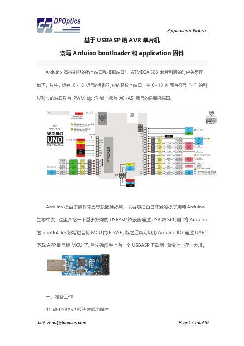
基于USBASP给AVR单片机烧写Arduino bootloader和application固件 Arduino 微控制器的数字端口和模拟端口与 ATMEGA 328 芯片引脚的对应关系图如下。
其中,标有 0~13 标号的引脚对应的是数字端口;在 0~13 前面有符号“~”的引脚对应的端口具有 PWM 输出功能;标有 A0~A5 标号的是模拟端口。
Arduino板由于操作不当导致固件损坏,或者想把自己开发的板子用到Arduino 生态中去,这里介绍一下基于外购的USBASP烧录器通过USB转SPI接口将Arduino 的bootloader烧写进目标MCU的FLASH,就之后就可以用Arduino IDE通过UART 下载APP到目标MCU了。
首先确保手上有一个USBASP下载器,淘宝上一搜一大堆。
一、准备工作:1)给USBASP板子装驱动程序注意选择好驱动程序所在名所以拒绝安装驱动程序,此名信息》一文,设置window 然后再尝试安装驱动程序。
电子”淘宝店买的下载板,但实太老了,结果智峰固件下载下载板到目标板连线错误,USBasp-win-driver-x86-文件到目标MCU。
下图是2)连接USBASP 到Ard注意USBASP 下载接口是插针,需要按下图的管脚定义序所在目录之后,win10可能会弹窗报错,说INF 序,此刻请参考《解决Win10安装驱动时,INF ndows 系统有条件重启,需选择“禁用驱动程序强序。
注意USBasp 的驱动程序也讲究版本,我图便宜板,但店家提供的驱动程序libusb0.dll 的版本是下载软件PROGISP V1.72运行时会报错说没有找误,我只得将驱动程序换成其他店家提供的V1.2.4-x64-ia64-v1.2.4,这之后才能成功下载bootlo 图是安装好驱动程序之后的“设备管理器”截屏:Arduino UNO 接口是10PIN 插针,而Arduino UNO 板载的下载脚定义用杜邦线飞线连接。
基于Arduino平台的微小型四轴飞行器设计与飞行控制系统实现

PB 0( IC P ) P B 1(0C 1 A) PB 2( SS /0 C1 B) PB 3( M 0SI /0 C2 ) PB 4(M IS 0) PB 5( SC K ) PB 6( X TA L 1 / T 0S C 1 ) PB 7( XTAL 2 / T 0SC 2 ) PD 0( RXD) PD 1 ( TXD) PD 2( INT 0 ) P D 3( IN T 1 ) PD 4( X CK / T0 ) PD 5( T1 ) PD 6( A IN 0 ) PD 7( A IN 1 )
i f — D ^ Z r c H w
ii
p
_s \,LED1 LED4
li 歷 E
H I—
|I " G
GND
SDA
" 1
— I~lH
GND 'I | P . O.luF GND
R ll 680
LED5
1+Q72
S
GND
GND LED2
LED6
LED7
图
3
总体硬件电路图
46 1 . 3 器件选型和电路设计
简单易用的 件 平台, 的 ArduinoIDE 是 是高性能、 低功耗的 8 位 AY5 单片机, 有 6 个 PWM 通道, 行器的各种动作, 其控制电路如图 4 所示。
U1
C
的, 易掌握。 ATMEGA328P 的 PWM , 从而控制四轴飞 + 3 .3 Y
Y1 XTAL
1 2 PW M 2 1 3 P M3 1 4 PW M 4 1 5 M IS 0 1 6 SCK 1 7 8 RXD 30 TXD 3 1 T H R 0TTLE 32 PW M 1 1 RO LL 2 PITC H r <i> 1 0 YAW
atmega328p晶体仪表的制作与程序
主题:atmega328p晶体仪表的制作与程序1. 简介atmega328p是一款由Atmel推出的低功耗、高性能的8位微控制器芯片,广泛应用于嵌入式系统和电子产品中。
通过合理的设计和程序编写,可以实现各种应用,比如晶体仪表。
下面将介绍如何制作atmega328p晶体仪表,并编写相应程序。
2. 材料准备- atmega328p芯片- 晶体振荡器- 电容- 电阻- LED数码管- 键盘- 电源及连线3. 硬件制作3.1 搭建电路连接3.2 确定晶体振荡器频率3.3 连接LED数码管3.4 键盘的连接3.5 完成整体电路连接4. 程序编写4.1 引用必要的库文件4.2 定义端口4.3 初始化程序4.4 程序编写流程及实现4.5 调试及优化5. 演示与调试5.1 上电演示5.2 程序功能演示5.3 调试过程及优化6. 总结atmega328p晶体仪表制作完成,并通过程序编写实现相应功能。
在制作过程中,需要严格按照电路连接图及引脚定义进行搭建,并注意电路的稳定性。
在程序编写时,需注重流程的合理性及代码的简洁性,以及功能的实现。
在演示与调试阶段,及时处理因硬件或软件方面的问题,并不断优化程序,以达到准确显示晶体信息的目的。
7. 参考资料- atmega328p数据手册- avr-gcc编程手册- 电路原理图及引脚定义通过上述步骤,我们可以很好的制作出atmega328p晶体仪表,并编写相应的程序,达到预期的功能。
希望以上内容对您有所帮助。
8. 扩展内容在制作atmega328p晶体仪表的过程中,除了搭建电路连接和编写程序外,还需要注意一些细节和技巧,以确保仪表的稳定性和准确性。
接下来,我们将深入探讨一些扩展内容,包括电路设计原则、程序优化技巧和应用场景的拓展。
8.1 电路设计原则在搭建电路连接过程中,电路设计是至关重要的一环。
为了确保atmega328p晶体仪表的稳定性和可靠性,需要遵循一些电路设计的原则:要合理设计电源部分。
Arduino UNO R3 产品参考指南说明书

Product Reference ManualSKU: A000066DescriptionThe Arduino UNO R3 is the perfect board to get familiar with electronics and coding. This versatile microcontroller is equipped with the well-known ATmega328P and the ATMega 16U2 Processor.This board will give you a great first experience within the world of Arduino.Target areas:Maker, introduction, industriesFeaturesATMega328P ProcessorMemoryAVR CPU at up to 16 MHz32KB Flash2KB SRAM1KB EEPROMSecurityPower On Reset (POR)Brown Out Detection (BOD)Peripherals2x 8-bit Timer/Counter with a dedicated period register and compare channels1x 16-bit Timer/Counter with a dedicated period register, input capture and compare channels1x USART with fractional baud rate generator and start-of-frame detection1x controller/peripheral Serial Peripheral Interface (SPI)1x Dual mode controller/peripheral I2C1x Analog Comparator (AC) with a scalable reference inputWatchdog Timer with separate on-chip oscillatorSix PWM channelsInterrupt and wake-up on pin changeATMega16U2 Processor8-bit AVR® RISC-based microcontrollerMemory16 KB ISP Flash512B EEPROM512B SRAMdebugWIRE interface for on-chip debugging and programmingPower2.7-5.5 volts444445556677777789910101111111212131313CONTENTS1 The Board1.1 Application Examples 1.2 Related Products 2 Ratings2.1 Recommended Operating Conditions 2.2 Power Consumption 3 Functional Overview3.1 Board Topology 3.2 Processor 3.3 Power Tree 4 Board Operation4.1 Getting Started - IDE4.2 Getting Started - Arduino Web Editor 4.3 Getting Started - Arduino IoT Cloud 4.4 Sample Sketches 4.5 Online Resources 5 Connector Pinouts5.1 JANALOG 5.2 JDIGITAL5.3 Mechanical Information5.4 Board Outline & Mounting Holes 6 Certifications6.1 Declaration of Conformity CE DoC (EU)6.2 Declaration of Conformity to EU RoHS & REACH 211 01/19/20216.3 Conflict Minerals Declaration 7 FCC Caution8 Company Information 9 Reference Documentation 10 Revision History1 The Board1.1 Application ExamplesThe UNO board is the flagship product of Arduino. Regardless if you are new to the world of electronics or will use the UNO as a tool for education purposes or industry-related tasks.First entry to electronics: If this is your first project within coding and electronics, get started with our most used and documented board; Arduino UNO. It is equipped with the well-known ATmega328P processor, 14 digital input/output pins, 6 analog inputs, USB connections, ICSP header and reset button. This board includes everything you will need for a great first experience with Arduino.Industry-standard development board: Using the Arduino UNO board in industries, there are a range of companies using the UNO board as the brain for their PLC’s.Education purposes: Although the UNO board has been with us for about ten years, it is still widely used for various education purposes and scientific projects. The board's high standard and top quality performance makes it a great resource to capture real time from sensors and to trigger complex laboratory equipment to mention a few examples.1.2 Related ProductsStarter KitTinkerkit Braccio RobotExample2 Ratings2.1 Recommended Operating ConditionsSymbol Description Min Max Conservative thermal limits for the whole board:-40 °C (-40°F)85 °C ( 185°F) NOTE: In extreme temperatures, EEPROM, voltage regulator, and the crystal oscillator, might notwork as expected due to the extreme temperature conditions2.2 Power ConsumptionSymbol Description Min Typ Max Unit VINMax Maximum input voltage from VIN pad6-20V VUSBMax Maximum input voltage from USB connector- 5.5V PMax Maximum Power Consumption--xx mA 3 Functional Overview3.1 Board TopologyTop viewBoard topologyRef.Description Ref.DescriptionX1Power jack 2.1x5.5mm U1SPX1117M3-L-5 RegulatorX2USB B Connector U3ATMEGA16U2 ModulePC1EEE-1EA470WP 25V SMD Capacitor U5LMV358LIST-A.9 ICPC2EEE-1EA470WP 25V SMD Capacitor F1Chip Capacitor, High DensityD1CGRA4007-G Rectifier ICSP Pin header connector (through hole 6)J-ZU4ATMEGA328P Module ICSP1Pin header connector (through hole 6)Y1ECS-160-20-4X-DU Oscillator3.2 ProcessorThe Main Processor is a ATmega328P running at up tp 20 MHz. Most of its pins are connected to the external headers, however some are reserved for internal communication with the USB Bridge coprocessor.3.3 Power TreePower tree4 Board Operation4.1 Getting Started - IDEIf you want to program your Arduino UNO while offline you need to install the Arduino Desktop IDE [1] To connect the Arduino UNO to your computer, you’ll need a Micro-B USB cable. This also provides power to the board, as indicated by the LED.4.2 Getting Started - Arduino Web EditorAll Arduino boards, including this one, work out-of-the-box on the Arduino Web Editor [2], by just installing a simple plugin.The Arduino Web Editor is hosted online, therefore it will always be up-to-date with the latest features and support for all boards. Follow [3] to start coding on the browser and upload your sketches onto your board.4.3 Getting Started - Arduino IoT CloudAll Arduino IoT enabled products are supported on Arduino IoT Cloud which allows you to Log, graph and analyze sensor data, trigger events, and automate your home or business.4.4 Sample SketchesSample sketches for the Arduino XXX can be found either in the “Examples” menu in the Arduino IDE or in the “Documentation” section of the Arduino Pro website [4]4.5 Online ResourcesNow that you have gone through the basics of what you can do with the board you can explore the endless possibilities it provides by checking exciting projects on ProjectHub [5], the Arduino Library Reference [6] and the online store [7] where you will be able to complement your board with sensors, actuators and more5 Connector PinoutsPinout5.1 JANALOGPin Function Type Description1NC NC Not connected2IOREF IOREF Reference for digital logic V - connected to 5V 3Reset Reset Reset4+3V3Power+3V3 Power Rail5+5V Power+5V Power Rail6GND Power Ground7GND Power Ground8VIN Power Voltage Input9A0Analog/GPIO Analog input 0 /GPIO10A1Analog/GPIO Analog input 1 /GPIO11A2Analog/GPIO Analog input 2 /GPIO12A3Analog/GPIO Analog input 3 /GPIO13A4/SDA Analog input/I2C Analog input 4/I2C Data line14A5/SCL Analog input/I2C Analog input 5/I2C Clock line5.2 JDIGITALPin Function Type Description1D0Digital/GPIO Digital pin 0/GPIO2D1Digital/GPIO Digital pin 1/GPIO3D2Digital/GPIO Digital pin 2/GPIO4D3Digital/GPIO Digital pin 3/GPIO5D4Digital/GPIO Digital pin 4/GPIO6D5Digital/GPIO Digital pin 5/GPIO7D6Digital/GPIO Digital pin 6/GPIO8D7Digital/GPIO Digital pin 7/GPIO9D8Digital/GPIO Digital pin 8/GPIO10D9Digital/GPIO Digital pin 9/GPIO11SS Digital SPI Chip Select12MOSI Digital SPI1 Main Out Secondary In13MISO Digital SPI Main In Secondary Out14SCK Digital SPI serial clock output15GND Power Ground16AREF Digital Analog reference voltage17A4/SD4Digital Analog input 4/I2C Data line (duplicated)18A5/SD5Digital Analog input 5/I2C Clock line (duplicated)5.3 Mechanical Information5.4 Board Outline & Mounting HolesBoard outline6 Certifications6.1 Declaration of Conformity CE DoC (EU)We declare under our sole responsibility that the products above are in conformity with the essential requirements of the following EU Directives and therefore qualify for free movement within markets comprising the European Union (EU) and European Economic Area (EEA).ROHS 2 Directive 2011/65/EUConforms to:EN50581:2012Directive 2014/35/EU. (LVD)Conforms to:EN 60950-1:2006/A11:2009/A1:2010/A12:2011/AC:2011 Directive 2004/40/EC & 2008/46/EC & 2013/35/EU,EMFConforms to:EN 62311:20086.2 Declaration of Conformity to EU RoHS & REACH 211 01/19/2021Arduino boards are in compliance with RoHS 2 Directive 2011/65/EU of the European Parliament and RoHS 3 Directive 2015/863/EU of the Council of 4 June 2015 on the restriction of the use of certain hazardous substances in electrical and electronic equipment.Substance Maximum limit (ppm)Lead (Pb)1000Cadmium (Cd)100Mercury (Hg)1000Hexavalent Chromium (Cr6+)1000Poly Brominated Biphenyls (PBB)1000Poly Brominated Diphenyl ethers (PBDE)1000Bis(2-Ethylhexyl} phthalate (DEHP)1000Benzyl butyl phthalate (BBP)1000Dibutyl phthalate (DBP)1000Diisobutyl phthalate (DIBP)1000Exemptions: No exemptions are claimed.Arduino Boards are fully compliant with the related requirements of European Union Regulation (EC) 1907 /2006 concerning the Registration, Evaluation, Authorization and Restriction of Chemicals (REACH). We declare none of the SVHCs (https://echa.europa.eu/web/guest/candidate-list-table), the Candidate List of Substances of Very High Concern for authorization currently released by ECHA, is present in all products (and also package) in quantities totaling in a concentration equal or above 0.1%. To the best of our knowledge, we also declare that our products do not contain any of the substances listed on the "Authorization List" (Annex XIV of the REACH regulations) and Substances of Very High Concern (SVHC) in any significant amounts as specified by the Annex XVII of Candidate list published by ECHA (European Chemical Agency) 1907 /2006/EC.6.3 Conflict Minerals DeclarationAs a global supplier of electronic and electrical components, Arduino is aware of our obligations with regards to laws and regulations regarding Conflict Minerals, specifically the Dodd-Frank Wall Street Reform and Consumer Protection Act, Section 1502. Arduino does not directly source or process conflict minerals such as Tin, Tantalum, Tungsten, or Gold. Conflict minerals are contained in our products in the form of solder, or as a component in metal alloys. As part of our reasonable due diligence Arduino has contacted component suppliers within our supply chain to verify their continued compliance with the regulations. Based on the information received thus far we declare that our products contain Conflict Minerals sourced from conflict-free areas.7 FCC CautionAny Changes or modifications not expressly approved by the party responsible for compliance could void the user’s authority to operate the equipment.This device complies with part 15 of the FCC Rules. Operation is subject to the following two conditions:(1) This device may not cause harmful interference(2) this device must accept any interference received, including interference that may cause undesired operation. FCC RF Radiation Exposure Statement:1. This Transmitter must not be co-located or operating in conjunction with any other antenna or transmitter.2. This equipment complies with RF radiation exposure limits set forth for an uncontrolled environment.3. This equipment should be installed and operated with minimum distance 20cm between the radiator &your body.English: User manuals for license-exempt radio apparatus shall contain the following or equivalent notice in a conspicuous location in the user manual or alternatively on the device or both. This device complies with Industry Canada license-exempt RSS standard(s). Operation is subject to the following two conditions:(1) this device may not cause interference(2) this device must accept any interference, including interference that may cause undesired operation of the device.French: Le présent appareil est conforme aux CNR d’Industrie Canada applicables aux appareils radio exempts de licence. L’exploitation est autorisée aux deux conditions suivantes :(1) l’ appareil nedoit pas produire de brouillage(2) l’utilisateur de l’appareil doit accepter tout brouillage radioélectrique subi, même si le brouillage est susceptible d’en compromettre le fonctionnement.IC SAR Warning:English This equipment should be installed and operated with minimum distance 20 cm between the radiator and your body.French: Lors de l’ installation et de l’ exploitation de ce dispositif, la distance entre le radiateur et le corps est d ’au moins 20 cm.Important: The operating temperature of the EUT can’t exceed 85℃ and shouldn’t be lower than -40℃. Hereby, Arduino S.r.l. declares that this product is in compliance with essential requirements and other relevant provisions of Directive 2014/53/EU. This product is allowed to be used in all EU member states.8 Company InformationCompany name Arduino S.r.lCompany Address Via Andrea Appiani 25 20900 MONZA Italy9 Reference DocumentationReference LinkArduino IDE(Desktop)https:///en/Main/SoftwareArduino IDE (Cloud)https:///editorCloud IDE Getting Started https:///projecthub/Arduino_Genuino/getting-started-with-arduino-web-editor-4b3e4aArduino Pro Website https:///proProject Hub https:///projecthub?by=part&part_id=11332&sort=trending Library Reference https:///reference/en/Online Store https:///10 Revision HistoryDate Revision Changesxx/06/20211Datasheet release。