deviation固件说明书解析
VaultGard Firmware升级说明说明书

VaultGard Firmware Upgrade ProcedureDownload the latest VaultGard firmware from the Network Protector web site at:/nwp, and save it to your hard drive.When upgrading to the latest VaultGard firmware from version 1.1.11 or later, skip the following instructions (a to d) and start with step 1 below. It is always a good idea to save the VaultGard configuration prior to upgrading firmware.Important steps to follow before starting the VaultGard firmware upgrade from 1.0.x:a. It is critical to follow the steps provided exactly as stated and to wait as specified on power up. Failureto do so may cause VaultGard to stop working. Also note that Firmware version 1.1.x will not workproperly with Internet Explorer 6. Please use IE7 or IE8.b. All configuration information will be lost during the firmware upgrade from 1.0.x to 1.1.x. Copy anyconfiguration information you will need from your existing 1.0.x VaultGard to a Word file for reference.You can select data on the VaultGard web pages, copy it, and paste it into a Word file if desired. Be sure to record your network settings!c. You must use the serial port cable for this upgrade, as the static IP address and other networkconfiguration information will be erased. It is only the initial firmware upgrade from version 1.0.x to1.1.x that will cause a loss of the IP address and associated network information.d. Before you load the new firmware, please go to the VaultGard Firmware web page and click <Reset> toclear the current configuration information.New Firmware upload:1. Browse to the VaultGard Firmware web page, and select the Control tab.2. Click <Upload Firmware> and select the firmware file 1.1.x.bin from your hard drive.3. The upload and update will take 5 to 10 minutes. The following messages will be displayed:“Uploading...do not change page or close browser”, followed by“Uploaded file, commencing update...”4. When the new firmware is loaded a pop-up message will report “Successful update”. Click <OK>, and the web page will transition back to the About tab, with the Status “New firmware applied, please reboot to use”5. Select the Control tab and click the <Reboot> button. Click <OK> to confirm the reboot.6. Wait about 5 minutes for VaultGard to reset and register the new 1.1.x firmware. Progress can be monitored on the serial port. Do not try to do any configuration until all the activity has completed on the serial port.If updating from firmware version 1.1.11 or later, the update process is complete at this step. Continue with step 7 when updating from firmware versions prior to 1.1.11.7. Using the serial port interface, press <Enter> to begin configuration. Select “Clear all config data” to reset the configuration from the older firmware database. This will cause VaultGard to reboot.8. Once again wait until all the activity has completed on the serial port.9. Now you may set the VaultGard IP address via the serial port.10. You may need to cycle power to VaultGard to get it to boot properly with the new firmware and IP address.11. Wait 1 to 2 minutes for VaultGard IP address to be registered, and then open Internet Explorer to the VaultGard IP address and log in.12. Browse to the Date/Time web page under VaultGard Configuration.•Click the Locale tab, select the correct time zone, and then click <Apply Settings>.•Click the Synchronization tab to select the time source for your network. If there is no NTP server or SCADA time server available select <Use Manual>.•Verify the correct time in the black rectangle on the right side of the header.。
DEVO系列遥控器在线升级使用手册中文
使用手册如何使用Devention DfuSe USB升级工具―――――――――――――――――――――――――――――――――――――――――――――――――――――――――――――1. 目录1. 目录 (1)2. 介绍 (1)3. 系统要求 (2)4. 如何进入程序升级 (3)4.1 devention DfuSe USB升级工具安装 (3)5. 用户使用界面详解 (7)5.1 固件升级界面 (7)5.2 固件升级操作 (9)5.3 配置升级界面 (13)5.4 配置升级操作 (14)5.5 库文件升级界面 (18)5.6 库文件升级操作 (19)5.7 重要提示 (26)6. 修正历史 (26)2. 介绍devention DfuSe USB升级包分为三类:固件、配置、库文件。
“固件”是指基于控制器的程序文件;“配置”是指各个模型模块的配置参数;“库文件”是指主要的图标、语言包以及语言文本。
本工具主要用于升级devention 2.4G遥控器产品的固件、配置和库文件。
本文详细描述如何安装devention DfuSe USB的驱动,以及如何使用此升级工具。
devention DfuSe USB升级包可在官方网站下载。
3. 系统要求为了在Windows操作系统上使用devention DfuSe USB升级工具,您必须在电脑上安装常用的Windows版本,如Windows 98SE,Millennium,2000,XP,或VISTA。
您可以在桌面上右击“我的电脑”,然后点击弹出菜单的“属性”,查看Windows操作系统的版本。
在“系统属性”的“常规”中显示操作系统类型。
如图1。
图1:系统属性对话框4. 如何进入程序升级4.1 devention DfuSe USB升级工具安装l软件安装运行DevoDfuSe_V1.0_Setup.exe 文件:安装向导将指导您安装Devention DfuSe USB 升级工具。
DeviceDrive Wi-Fi模块说明书

U S E R M A N U A LDeviceDrive clickDeviceDrive click is a complete Cloud-on-M odule solution with Wi-Fi functionality and an integrated PCB antenna. The onboard WRF01-M 24A module comes preloaded with DeviceDrive firmware.To our valued customersI want to express my thanks to you for being interested in our products and for having confidence in Mikroelektronika.The primary aim of our company is to design and produce high quality electronic products and to constantly improve the performance thereof in order to better suit your needs.Nebojsa MaticCEOTable of ContentsIntroduction 4 1. Set up your product in the cloud 59SimulatortheClient2. InstallingDeviceDrive10clickup3. Set103.1. Connect DeviceDriveclick3.2 Connecting to PC over USB/UART converter113.3 Setting up DeviceDrive click with LinkUp 134. Device Simulator 15polling 16 Data4.1.5. Advanced 176. Upgrade demo board 19IntroductionWRF01 is a Wi-Fi (802.11B/G/N) module from DeviceDrive. By using the DeviceDrive click, you can connect it to your PC and simulate real device behaviour, to learn how the device works and how it communicates to the cloud and to the app.This document introduces the WRF01 Client Simulator and aims at giving you a quick start for developing with the DeviceDrive click. The program communicates with the DeviceDrive click trough the serial ports and is suited for acting as a client and for prototyping IoT-Products.The following sections give the steps how to get started:∫ Section 4: Set up your product in the cloud∫ Section 5: Installing the software∫ Section 6: Set up DeviceDrive click∫ Section 7: Simulate IoT device∫ Section 8: Send custom DeviceDrive click messages∫ Section 9: Upgrading your WRF011. Set up your product in the cloudIn order to use the DeviceDrive click with the DeviceDrive cloud and the client simulator you need to sign up on the DeviceDrive management portal. If you already have an account, you can just sign in and create a new product on your account. Goal: Get a valid product key to use with this tutorialProcedure for signing up:1.S ign up at https://2.P ress email signup3. E nter your email address and press“Send verification code”4. Y ou will receive an email with your verification code. Copy this code to your clipboard and paste into the registration form. Then click “Verify code”.5. E nter your preferred password and your name.Then press “Create”.6. R egister your company name. This is the name of your DeviceDrive management account. It can contain several users and several products.7. R egister your test product. Enter a name for your product and select “Internal agent”. Then copy the product key to your clip board and press“Save”.8. P aste the product key somewhere (e.g. Notepad) so that you can use it later.2. Installing the Client SimulatorIf your Antivirus complains that the software package is not signed, please ignore and run the install anyway. Download the software from https:///downloadsRun the installer. This will install the software and add the examples folder to the program folder. After the install is finished, you can launch the program from the start menu or the desktop icon.3. Set up DeviceDrive clickThis section describes how to connect your DeviceDrive click to the network and configure your product key.3.1 Connect DeviceDrive clickConsidering that DeviceDrive click is a board withUART interface you will need additional board to make it working. There are severals ways that you can put in use your DeviceDrive click board.Option 1 – click USB adapter (or any USB to UART converter)Option 2 – clicker 2 (or any other development system with mikroBUS™ socket). 2 13.2 Connecting to PC over USB/UART converter Array Your computer will recognize the device, and designate a COM port for it. As soon this is done, will see the COM port in the dropdown (1) in the picture above.If the connection is successful, the color of the Connection Status Indicator (2) will change from Red to Green. The Host port communication window will give you the exact communication log between the Simulator and WRF01. Use this to learn about how the WRF01 behaves in a normaloperating cycle.It is possible to mix up the host port and the log port in the two windows. It is recommended to plug in the HOST port first, and then select the port in the host communication window before connecting the log port.When DeviceDrive click is connected, enter the product key (the one from the management portal) in to the field marked “Product Key” (3). If you want the device online right away enter the network ssid and password in their fields. If your product key is defined as a “Forwarding product”, you can enter these right away, and start sending data, but if you have an “Internal product” and wish to use the mobile app SDK’s, you should LinkUp using the app. In addition, you can attach the log port to your computer with an USB mini cable. This will also register as a COM port in your system. In the “Log port Output” window, select the new COM port. Check the status indicator on the right-hand side to see that the connection is successful.When you are ready, press “Init” (4). This will initiate the WRF01. You should see the message “Response OK” in the Serial output window, and if you attached the Log port, you should see the WRF01 internal workings while connecting to your access point (router).Hold your mouse over the quick commands to get more information about them.3.3 Setting up DeviceDrive click with LinkUpLinkup is only required if your device is an “Internal product” in the DeviceDrive system.To make the DeviceDrive click ready for LinkUp, use the “Show Device” (1)button to enable the local AP.You can also use SmartLinkup to initiate the SmartLinkup procedure. This procedure lets the user connect the device withouthaving to use the Soft AP.The DeviceDrive Playground App is available on Apple Store and Android Play. When you are using the LinkUp procedure, the SSID and password for your network is sent, along with the security token for your device. This is the reason that you need to use the LinkUp system when working with Internal Products. For more information about how to use the DeviceDrive Playground app and the internal product, please see this video and the documentation.The screenshots below show how the Playground app lets you link up your new device and show the simulated data from the device simulator.The device state is shown in the app after the introspect and current state have been sent to the cloud. The next section describes how to simulate device behavior.4. Device Simulator Array On the top of the DeviceDrive WRF01 Client Simulator, you will find the Device Simulator tab. This tab gives you the opportunity to test the introspection functionality and lets you integrate the DeviceDrive click with an app with our SDK or the DeviceDrive Playground app.Before you can start simulation, please make sure that you followed the steps in chapter Feil! Fant ikke referansekilden., 6.1 and 6.2.To be able to send a status update, first press the “Send Introspect” (1) button. This sends a message to the cloud with the “capabilities” of your product. See the Serial specification documentation or this video about more information about the introspection document. This is a prerequisite for the APP you’re using to control your device.When the introspection document is sent you can click the temperature or light controller to send devicedata to the cloud. The app will automatically updatewith the new device data.4.1 Data pollingapp to the device. If you are using the DeviceDrivePlayground app, try to flip the button marked“Light”.Press the “Poll” (1) button to read pending statusupdates from the app. You can check “Auto poll” tolet this happen automatically at the given interval.The simulated state will be updated according tothe received messages.∫ Polling requires SSL to be enabled on the WRF01 (versions below 4.0). Please press “Init” again if the system does not receive messages.∫ Version 4.0 supports MQTT, so if the WRF01 is already connected to the server, the messages from the app will appear asynchronously without polling.∫ There is no queue system in this software, so if you try to send or receive a lot of messages in rapid succession, you might experience the “System busy” error message. To resolve this, wait for the WRF01 to complete the current operation. This can be seen in the Log window. In a real application you can use our client SDK source code where a queue is implemented.5. Advanced Array Use the Advanced screen to send custom messages and choose from a set of predefined message templates.This screen is suited for those who wish to tweak the messages sent to the server, or to test the whole range of the available commands for the WRF01. By default, the two drop-down menus should point to the folder that came bundled with the installation. To use the WRF01 commands, select “wrf01 commands” (1) in the first dropdown. In the second, you will be able to see the available commands. These match the “Serial specification documentation” and you can enter, or change the properties / values in the text field below.Before pressing send, make sure that there is an EOT character at the end of your transmission. Itwill be marked with a small rectangle after yourlast bracket.If there is no EOT char, press the “Add EOT” button.command to the device.In addition to all of the available WRF01 commands,this software comes with some examples ofintrospection and status messages you can try.In the text field you can add your own text or messagesand send to the WRF01. If you are using your owncloud and require special messages, this is where youcan send them.The “Browse” (2) button lets you select the base folderto show template messages from.This software strips your message of all <CR> <LF> characters before sending them to the WRF01. In a real-world application, do not use these characters in a WRF01 command. They have to comply exactly with the serial specification. If a command does not start with exactly {"devicedrive": the message will be interpreted as a cloud message transfer, and not a WRF01 command.6. Upgrade demo board The upgrade pane lets you easily experiment with upgrading and downgrading your WRF01 module on DeviceDrive click.Notice that the upgrade itself has to be defined in the management portal.Perform each of the steps manually or just press “Do all” (1) to upgrade automatically (but you still need to define the upgrade in the managementportal).Define the upgrade in the management portal (click the link in point 1) (2).Click each of point 2-4 or just press “Do all” to run automatically.You should see that the current version field updates to the selected version (3).DISCLAIMERAll the products owned by MikroElektronika are protected by copyright law and international copyright treaty. Therefore, this manual is to be treated as any other copyright material. No part of this manual, including product and software described herein, may be reproduced, stored in a retrieval system, translated or transmitted in any form or by any means, without the prior written permission of MikroElektronika. The manual PDF edition can be printed for private or local use, but not for distribution. Any modification of this manual is prohibited. MikroElektronika provides this manual ‘as is’ without warranty of any kind, either expressed or implied, including, but not limited to, the implied warranties or conditions of merchantability or fitness for a particular purpose. MikroElektronika shall assume no responsibility or liability for any errors, omissions and inaccuracies that may appear in this manual. In no event shall MikroElektronika, its directors, officers, employees or distributors be liable for any indirect, specific, incidental or consequential damages (including damages for loss of business profits and business information, business interruption or any other pecuniary loss) arising out of the use of this manual or product, even if MikroElektronika has been advised of the possibility of such damages. MikroElektronika reserves the right to change information contained in this manual at any time without prior notice, if necessary.HIGH RISK ACTIVITIESThe products of MikroElektronika are not fault – tolerant nor designed, manufactured or intended for use or resale as on – line control equipment in hazardous environments requiring fail – safe performance, such as in the operation of nuclear facilities, aircraft navigation or communication systems, air traffic control, direct life support machines or weapons systems in which the failure of Software could lead directly to death, personal injury or severe physical or environmental damage (‘High Risk Activities’).MikroElektronika and its suppliers specifically disclaim any expressed or implied warranty of fitness for High Risk Activities.TRADEMARKSThe MikroElektronika name and logo, mikroC, mikroBasic, mikroPascal, Visual TFT, Visual GLCD, mikroProg, Ready, MINI, mikroBUS™, EasyPIC, EasyAVR, Easy8051, Click boards™ and mikromedia are trademarks of MikroElektronika. All other trademarks mentioned herein are property of their respective companies.All other product and corporate names appearing in this manual may or may not be registered trademarks or copyrights of their respective companies, and are only used for identification or explanation and to the owners’ benefit, with no intent to infringe.The FTDI Chip® and Windows® logos and product names are trademarks of FTDI Chip and Microsoft® in the U.S.A. and other countries.Copyright © 2019 MikroElektronika. All Rights Reserved.If you want to learn more about our products, please visit our website at If you are experiencing some problems with any of our products or just need additional information, please place your ticket at /supportIf you have any questions, comments or business proposals, do not hesitate to contact us at*****************Designed by Mikroelektronika Ltd.。
MGate MB3660系列固件发布说明书
Firmware for MGate MB3660 Series Release NotesSupported Operating SystemsNotesChangesApplicable ProductsBugs Fixed• Vulnerability issues (higher level or above) have been fixed, following a Nessus and Defensics scan.• Supports MXconfig v2.6 and MXview v3.1.8.• Enhanced the System Log display.• Strengthened the TLS cipher suite for security enhancement.• Enhanced MOXA commands under the account login process.• Adjusted Telnet default settings from enable to disable.• Disabled unsecure TLS 1.0 and TLS 1.1.• Enhanced Accessible IP List feature.• Added CSRF attack protection for login webpage.• Serial parameters might have been incorrect when switching between ASCII and RTU modes.• Fixed the incomplete display in the web console.• Fixed SNMPv3 issues.• Fixed the MGate's failure to get an IP address under DHCP mode.• Fixed https connections that might have caused the web service to stop working.EnhancementsN/AN/AN/ANew FeaturesN/AN/ASupported Operating SystemsNotesChangesApplicable ProductsBugs FixedN/AN/AEnhancementsN/AN/ASupports MGate MB3660I-8-2AC and MGate MB3660I-16-2AC new hardware version v1.1.New FeaturesN/AN/ASupported Operating SystemsNotesChangesApplicable ProductsBugs Fixed• Accessible IP List supports denying Web/Telnet console access.• In Agent mode as a Modbus ASCII master, MGate would hang after plugging and unplugging a serial cable.EnhancementsN/AMGate MB3660-8-J-2AC, MGate MB3660I-16-2AC, MGate MB3660-16-J-2AC, MGate MB3660-8-2AC, MGate MB3660-8-2DC, MGate MB3660I-8-2AC, MGate MB3660-16-2AC, MGate MB3660-16-2DC• Supports security features based on IEC-62443.New FeaturesN/AN/ASupported Operating SystemsNotesChangesApplicable ProductsBugs Fixed• Enhanced the complexity of token generation to protect against CSRF attacks.• Enhanced the complexity of the key for password encryption in the web console login process.• Encrypts sensitive information in exported configuration file.• Enhanced the display of auto detection results in MODBUS transparent mode.• Firmware version check problem when upgrading firmware for MGate MB3660I-16-2AC, MB3660-8-J-2AC, and MB3660-16-J-2AC.• Modbus RTU communication would fail if FIFO was disabled.• The FIFO setting would not be activated after clicking the “Submit” button.• Stack-based buffer overflow issue in web console which may cause web service corruption.• Challenge ID generation problem which may cause web console login failure.EnhancementsN/AMGate MB3660-8-J-2AC, MGate MB3660I-16-2AC, MGate MB3660-16-J-2AC, MGate MB3660-8-2AC, MGate MB3660-8-2DC, MGate MB3660I-8-2AC, MGate MB3660-16-2AC, MGate MB3660-16-2DCN/ANew FeaturesN/AN/ASupported Operating SystemsNotesChangesApplicable ProductsBugs Fixed• Improved security of the TCP sequence number.• Improved beeper behavior in DHCP mode.• Modbus RTU diagnose error in agent mode.• Initial error relay state when powered on.EnhancementsN/AMGate MB3660-8-J-2AC, MGate MB3660I-16-2AC, MGate MB3660-16-J-2AC, MGate MB3660-8-2AC, MGate MB3660-8-2DC, MGate MB3660I-8-2AC, MGate MB3660-16-2AC, MGate MB3660-16-2DC• Supports MGate MB3660I-16-2AC, MGate MB3660-8-J-2AC, MGate MB3660-16-J-2AC models.New FeaturesN/AN/ASupported Operating SystemsNotesChangesApplicable ProductsBugs Fixed• The Modbus master in agent mode supports up to 256 commands for each serial port.• Supports multi-master in "routing by IP address" and "routing by TCP port" modes.• Supports sorting of commands in the I/O mapping page.• Supports auto internal memory assign in the command page.• Supports Modbus slave ID 255 in transparent mode.• User password and SNMP community name may be exposed by a buffer overflow issue.EnhancementsN/AMGate MB3660-8-2AC, MGate MB3660-8-2DC, MGate MB3660I-8-2AC, MGate MB3660-16-2AC,MGate MB3660-16-2DC• Supports Auto Device Routing in Modbus transparent mode.• Supports Modbus TCP traffic logs.New FeaturesN/AN/ASupported Operating SystemsNotesChangesApplicable ProductsBugs FixedN/A• Bug in Modbus Master mode which may cause the MGate to reboot under some conditions.EnhancementsN/AMGate MB3660-8-2AC, MGate MB3660-8-2DC, MGate MB3660I-8-2AC, MGate MB3660-16-2AC,MGate MB3660-16-2DCN/ANew FeaturesN/AN/ASupported Operating SystemsNotesChangesApplicable ProductsBugs FixedN/A• Initial delay issue which would stop Modbus communication.EnhancementsN/AMGate MB3660-8-2AC, MGate MB3660-8-2DC, MGate MB3660I-8-2AC, MGate MB3660-16-2AC,MGate MB3660-16-2DCN/ANew FeaturesN/AN/ASupported Operating SystemsNotesChangesApplicable ProductsBugs FixedN/A• Fix the algorithm which may cause Modbus transparent mode to stop communication.• Serial port 13 interface initialization problem.• Modbus traffic exceptions in the serial port are not handled well, which might cause the serial port to stop transmitting data.• When the "Read memory address" is greater or equal to 8192 for the "01 - Read Coils" or "02 -Read Discrete Inputs" functions, data will be written to the wrong internal memory address.EnhancementsN/AMGate MB3660-8-2AC, MGate MB3660-8-2DC, MGate MB3660I-8-2AC, MGate MB3660-16-2AC,MGate MB3660-16-2DCN/ANew FeaturesN/AN/ASupported Operating SystemsNotesChangesApplicable ProductsBugs FixedN/AN/AEnhancementsN/AMGate MB3660-8-2AC, MGate MB3660-8-2DC, MGate MB3660I-8-2AC, MGate MB3660-16-2AC,MGate MB3660-16-2DC• First release.New FeaturesN/AN/A。
意法半导体DFUSe USB设备固件升级入门说明书
UM0412User manualDfuSe USB设备固件升级意法半导体扩展入门引言本文档介绍了演示用户界面,该界面专为介绍STMicroelectronics设备固件升级库的开发而设计。
该库的描述(包括其应用编程接口)包含在“DfuSe应用编程接口”文档中,并随DfuSe软件一起安装。
2019年3月Doc ID 13379 Rev 1 [English Rev 4]1/22目录UM0412目录1入门指南 . . . . . . . . . . . . . . . . . . . . . . . . . . . . . . . . . . . . . . . . . . . . . . . . . . . 51.1系统要求 . . . . . . . . . . . . . . . . . . . . . . . . . . . . . . . . . . . . . . . . . . . . . . . . . . . 51.2演示程序的组成部分 . . . . . . . . . . . . . . . . . . . . . . . . . . . . . . . . . . . . . . . . . . 61.3DfuSe演示程序安装 . . . . . . . . . . . . . . . . . . . . . . . . . . . . . . . . . . . . . . . . . . 61.3.1软件安装 . . . . . . . . . . . . . . . . . . . . . . . . . . . . . . . . . . . . . . . . . . . . . . . . . 61.3.2硬件安装 . . . . . . . . . . . . . . . . . . . . . . . . . . . . . . . . . . . . . . . . . . . . . . . . . 62DFU文件 . . . . . . . . . . . . . . . . . . . . . . . . . . . . . . . . . . . . . . . . . . . . . . . . . . 123用户界面说明 . . . . . . . . . . . . . . . . . . . . . . . . . . . . . . . . . . . . . . . . . . . . . . . 133.1DfuSe演示 . . . . . . . . . . . . . . . . . . . . . . . . . . . . . . . . . . . . . . . . . . . . . . . . 133.2DFU文件管理器 . . . . . . . . . . . . . . . . . . . . . . . . . . . . . . . . . . . . . . . . . . . . 153.2.1“想要执行”对话框 . . . . . . . . . . . . . . . . . . . . . . . . . . . . . . . . . . . . . . . . . . 153.2.2“文件生成”对话框 . . . . . . . . . . . . . . . . . . . . . . . . . . . . . . . . . . . . . . . . . . 163.2.3“文件提取”对话框 . . . . . . . . . . . . . . . . . . . . . . . . . . . . . . . . . . . . . . . . . . 174分步流程 . . . . . . . . . . . . . . . . . . . . . . . . . . . . . . . . . . . . . . . . . . . . . . . . . . 194.1DfuSe演示步骤 . . . . . . . . . . . . . . . . . . . . . . . . . . . . . . . . . . . . . . . . . . . . . 194.1.1如何上传DFU文件 . . . . . . . . . . . . . . . . . . . . . . . . . . . . . . . . . . . . . . . . . 194.1.2如何下载DFU文件 . . . . . . . . . . . . . . . . . . . . . . . . . . . . . . . . . . . . . . . . . 194.2DFU相关文件生成步骤 . . . . . . . . . . . . . . . . . . . . . . . . . . . . . . . . . . . . . . . 204.2.1如何从S19/Hex/Bin文件生成DFU文件 . . . . . . . . . . . . . . . . . . . . . . . . . . 204.2.2如何从DFU文件提取S19/Hex/Bin文件 . . . . . . . . . . . . . . . . . . . . . . . . . . 20 5版本历史 . . . . . . . . . . . . . . . . . . . . . . . . . . . . . . . . . . . . . . . . . . . . . . . . . . 212/22Doc ID 13379 Rev 1 [English Rev 4]UM0412表格索引表格索引表1.“DfuSe演示”对话框说明 . . . . . . . . . . . . . . . . . . . . . . . . . . . . . . . . . . . . . . . . . . . . . . . . . . . 14表2.“文件生成”对话框说明. . . . . . . . . . . . . . . . . . . . . . . . . . . . . . . . . . . . . . . . . . . . . . . . . . . . . 16表3.“Multi bin injection”对话框说明 . . . . . . . . . . . . . . . . . . . . . . . . . . . . . . . . . . . . . . . . . . . . . . 17表4.“文件提取”对话框说明. . . . . . . . . . . . . . . . . . . . . . . . . . . . . . . . . . . . . . . . . . . . . . . . . . . . . 18表5.文档版本历史 . . . . . . . . . . . . . . . . . . . . . . . . . . . . . . . . . . . . . . . . . . . . . . . . . . . . . . . . . . . 21表6.中文文档版本历史. . . . . . . . . . . . . . . . . . . . . . . . . . . . . . . . . . . . . . . . . . . . . . . . . . . . . . . . 21Doc ID 13379 Rev 1 [English Rev 4]3/22图片索引UM0412图片索引图1.系统属性对话框. . . . . . . . . . . . . . . . . . . . . . . . . . . . . . . . . . . . . . . . . . . . . . . . . . . . . . . . . . . 5图2.选择安装位置 . . . . . . . . . . . . . . . . . . . . . . . . . . . . . . . . . . . . . . . . . . . . . . . . . . . . . . . . . . . . 7图3.驱动选择选项 . . . . . . . . . . . . . . . . . . . . . . . . . . . . . . . . . . . . . . . . . . . . . . . . . . . . . . . . . . . . 8图4.驱动选择. . . . . . . . . . . . . . . . . . . . . . . . . . . . . . . . . . . . . . . . . . . . . . . . . . . . . . . . . . . . . . . . 9图5.从磁盘安装 . . . . . . . . . . . . . . . . . . . . . . . . . . . . . . . . . . . . . . . . . . . . . . . . . . . . . . . . . . . . . 10图6.进度消息. . . . . . . . . . . . . . . . . . . . . . . . . . . . . . . . . . . . . . . . . . . . . . . . . . . . . . . . . . . . . . . 10图7.警告消息. . . . . . . . . . . . . . . . . . . . . . . . . . . . . . . . . . . . . . . . . . . . . . . . . . . . . . . . . . . . . . . 11图8.安装完成. . . . . . . . . . . . . . . . . . . . . . . . . . . . . . . . . . . . . . . . . . . . . . . . . . . . . . . . . . . . . . . 11图9.“DfuSe演示”对话框. . . . . . . . . . . . . . . . . . . . . . . . . . . . . . . . . . . . . . . . . . . . . . . . . . . . . . . 13图10.“编辑选项字节”对话框. . . . . . . . . . . . . . . . . . . . . . . . . . . . . . . . . . . . . . . . . . . . . . . . . . . . . 15图11.“想要执行”对话框 . . . . . . . . . . . . . . . . . . . . . . . . . . . . . . . . . . . . . . . . . . . . . . . . . . . . . . . . 15图12.“生成”对话框. . . . . . . . . . . . . . . . . . . . . . . . . . . . . . . . . . . . . . . . . . . . . . . . . . . . . . . . . . . . 16图13.“Multi bin injection”对话框. . . . . . . . . . . . . . . . . . . . . . . . . . . . . . . . . . . . . . . . . . . . . . . . . . 17图14.“提取”对话框. . . . . . . . . . . . . . . . . . . . . . . . . . . . . . . . . . . . . . . . . . . . . . . . . . . . . . . . . . . . 17 4/22Doc ID 13379 Rev 1 [English Rev 4]UM0412入门指南Doc ID 13379 Rev 1 [English Rev 4]5/221入门指南1.1 系统要求为了在Windows 操作系统上使用DfuSe 演示程序,PC 上的Windows 必须是较新的版本,例如Windows 98SE 、Millennium 、2000、XP 或VISTA 。
deviation固件说明书解析

DEVIATION说明书第一版前言年初购入devo10,那个论坛成为神控的遥控器。
神控处了这个控的硬件可圈可点外,最重要的一点就是刷入deviation(官网,英文的)这个固件后兼容dsm2等多种主流的制式,实现一控多种接收共用。
而且其开放的平台,能够不断升级增加功能,更有suv等大大的不断奉献,至此deviation 版本走了3.1版,链接/thread-241130-1-1.html感谢各位模友大大的无私奉献,我有幸用上这个神器。
经过一番专研,翻阅说明书后终于大概了解如何设置和运用,deviation的自由度很高,各个通道均可以自定义,让你打造属于自己的控,用起来随心所欲。
里面的混控器是属于底层的混控,自由度很高,不过的确需要一段时间来理解,如果学会了会觉得很好用的,想怎混就怎混。
由于官方说明书是英文的,而且不是说得很明白,加上经常有模友问及如何设置,于是本人萌生出写一下中文说明书的念头,再加点应用例子,务求各位模友更易明白上手,而且通过大家的讨论还能加深本人对这个固件的认识,达到共同进步的目的。
一下都是本人自己的认识跟见解,如有问题请提出来大家切磋讨论。
hilitiQ群:2954863552013年8月22日主界面这个是开机后的主界面,在这里吐槽一下我见过的devo10屏幕贴上都是有灰的,难道厂里贴膜的那个车间就在矿里?至少这一点学一下天地飞吧,出厂膜漂亮得很。
以下是菜单设置,首先是主菜单,这个没什么好说的,很简单明白通用模式进入模型设置,如果之前接触过遥控的话,这些名词也是很清楚明白的,如果还没有搞明白的话,潜水去吧骚年~~好了,现在进入模型设置里面的模型设置菜单(控上是这样写的,不要怪我),第一个模型文件那里,看到黑色部分左右会有箭头的是可以进行左右选择,这里会有读取,复制,模板,重置4个选项。
读取完后不用重启就可以马上工作了。
复制就是把现有模型设置拷贝到另一个模型文件,模板是控自带的设置模板,里面已经有一些预先调好的参数,重置就是格式化~~这个模型文件恢复出厂设定模型类型那个选项可以选择固定翼跟直升机,如果选择直升机的话可以按ent 进入进行斜盘设置跟斜盘的混控比率调节功率调节,越大就越远(傻子都懂),原厂最大好像是100mw,华科尔提供的小日本版本固件的最大10mw。
GALEEDEVO7E固件刷机指南
GALEEDEVO7E固件刷机指南GALEE DEVO7E 是我为华科尔DEVO7E 遥控器编写的中⽂固件,之所以写这个固件,是为了弥补官⽅固件限制功率,⽽DEVIATION 固件⼜没有7E 的中⽂版本。
当然,固件的操作⽅式完全按照我⾃⼰对模型的理解来设计,可能与市⾯上现有的遥控器有所不同,也许会引起您的使⽤不适,请⽂明评价。
本固件的编写,⼤量使⽤了DEVIATION 的源码,我的最主要⼯作是重写了整个⽤户操作界⾯,使得固件体积⼤⼤缩减,⾼频头、U 盘这两部分代码沿⽤了DEVIATION 的开源成果。
同时,根据GPL 协议,GALEE 固件也是开源的,源码下载将另⾏提供。
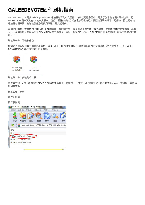
刷机第⼀步:下载软件包你需要下载华科尔官⽅的刷机⼯具包,以及GALEE DEVO7E.RAR(当然你能看到此⽂档说明已经下载到了),把GALEE DEVO7E.RAR 解压缩到某个⽬录备⽤。
刷机第⼆步:安装刷机⼯具打开官⽅的zip 包,双击执⾏DEVO DFU SE ⼯具软件,安装它,⼀路“下⼀步”就装好了,最后勾选”Launch...”复选框,直接运⾏刷机软件。
配置⽂件:刷机固件:刷机第三步⽤到刷机第三步:刷将你的遥控器⽤USB 线接上电脑(标准MINI USB 线都可以),然后按住“遥控器的EXT 键”打开“遥控器的电源”。
电脑会提⽰安装驱动程序等等,很快就装好了,这时候刷机软件的设备列表会显⽰“STM Device in DFU Mode”,按下图步骤操作。
点了"Upgrade”以后还有个确认过程,点“是(Y)”,然后就开始刷了1.这⾥亮了2.点这⾥浏览选择⽂件3.这个提⽰表明固件包没错 4.确认⼀下是GALEE 固件5.⼤胆点下去吧,反正这控便宜!等看到这个绿⾊的提⽰,意思是“升级成功”,就说明刷机完成,接着进⼊下⼀步操作。
刷机第四步:格式化遥控器不要拔掉遥控器上的USB线,关掉遥控器的电源,然后按住“遥控器的ENT键”打开“遥控器的电源”,可以看到遥控器的屏幕上显⽰⼀个USB的图标(此处偷懒不截图),电脑上则开始安装驱动,最后出现⼀个U盘,容量是2M左右。
DeviceNet Adapter 22-COMM-D 固件 v1.011 发布说明书
Release Note22-COMM-D DeviceNet Adapter Firmware v1.011This release note describes major revision 1, minor revision 11 of firmware for 22-COMM-D DeviceNet adapters.IntroductionThe following information is included in this document: EnhancementsThis section describes the enhancements provided in this revision of firmware:•Improved the reliability of the DSI communication between the adapter and the drive(s).•Improved the reliability of fragmented explicit message transactions on the network.Corrected AnomaliesThis section describes the anomaly corrected in this revision of firmware:•In Multi-Drive mode, corrected an issue with the integrity of the I/O data transferred between the network and the drive.For information about:See page:Enhancements 1Corrected Anomalies 1Determining Firmware Revision 2Firmware Flashing 4Restrictions 7Compatible Revisions 8Rockwell Automation Support 8Product Satisfaction Return 8222-COMM-D DeviceNet Adapter Firmware v1.011Determining Firmware Revision This section describes procedures to determine the firmware revision of your 22-COMM-D DeviceNet adapter.Using the Optional, External LCD HIM (22-HIM-**)22-COMM-D DeviceNet Adapter Firmware v1.0113Using DriveExplorer Lite/Fullunch DriveExplorer and go online (via 1203-USB or 22-SCM-232converter) with the drive that is connected to the adapter.2.In the DriveExplorer treeview, click on 22-COMM-D DeviceNetModule as shown in Figure 1.3.Click the information icon to display the adapter’s properties screen.4.The “Revision:” field shows the present revision (for example, 1.010) ofthe adapter firmware.Figure 1 Information Icon in DriveExplorer WindowTIP: When clicking on the 22-COMM-D adapter using version 5.01 orhigher DriveExplorer Lite/Full, the adapter firmware revision is also shownin the right pane of the DriveExplorer window.Step 4422-COMM-D DeviceNet Adapter Firmware v1.011Using DriveExecutive unch DriveExecutive and go online with the drive that is connected to the adapter.2.In the DriveExecutive treeview, click on 22-COMM-D as shown in Figure 2.3.Click the information icon to display the adapter’s Properties screen.4.The “Revision:” field shows the present revision (for example, 1.010) of the adapter firmware.Figure 2 Information Icon in DriveExecutive Window Firmware FlashingThis section describes procedures to flash upgrade your adapter firmware. Flash kits for drives, communications adapters, and peripherals are provided on the Allen-Bradley Web Updates site located at /support/abdrives/webupdate . Flashing can only be performed using a 1203-USB or 22-SCM-232 converter. For information about how to connect to your drive, please refer to the 1203-USB or 22-SCM-232 User Manual. They can be viewed/downloaded on the Literature Library web site located at .Step 4ATTENTION: Risk of permanent equipment damage exists. Once a flash update has been started, do not remove power from the drive (or the 22-XCOMM-DC-BASE External Comms Kit, if used) until after the download has completed and the adapter MOD status indicator starts FLASHING GREEN. If power is removed before this occurs, the adapter may be permanently damaged. An adapter that has been damaged in this22-COMM-D DeviceNet Adapter Firmware v1.0115Installing the Flash Kit1.Install the flash kit utility from the Allen-Bradley Web Updates site forthe 22-COMM-D adapter. (This also automatically installs theControlFLASH utility and deploys the firmware files for use withHyperTerminal on your computer.)2.You are now ready to use DriveExplorer, DriveExecutive,ControlFLASH or HyperTerminal to update the adapter. Refer to the respective section below and follow the instructions.Using DriveExplorer Lite/Full to Flash Update1.With the Flash Kit installed (see Installing the Flash Kit), launchDriveExplorer and go online (via a 1203-USB or 22-SCM-232converter) with the drive that is connected to the adapter.2.In the DriveExplorer treeview, click on 22-COMM-D DeviceNetModule. Then click the information icon as shown in Figure 1 todisplay the adapter’s Properties screen.3.On the 22-COMM-D Properties screen, click the Details tab.Important:This update may cause the adapter parameters to revert to their default values. You may want to save yourconfiguration using DriveExplorer or the HIM CopyCatfeature before upgrading.4.To start the flash update, click the Flash Update… button. Then select“v1.011.xx Full” from the list of available updates and click Next >.Follow the remaining screen prompts until the flash update procedure completes and displays the new firmware version (v1.011).Using DriveExecutive to Flash Update1.With the Flash Kit installed (see Installing the Flash Kit), launchDriveExecutive and go online (via a 1203-USB or 22-SCM-232converter) with the drive that is connected to the adapter.2.In the DriveExecutive treeview, click on 22-COMM-D adapter. Thenclick the information icon as shown in Figure 2 to display the adapter’s Properties screen.3.On the 22-COMM-D Properties screen, click the Component Detailstab.Important:This update may cause the adapter parameters to revert to their default values. You may want to save yourconfiguration using DriveExecutive or the HIM CopyCatfeature before upgrading.4.To start the flash update, click the Flash Update button. Then select the22-COMM-D from the list of available devices and click Next >.622-COMM-D DeviceNet Adapter Firmware v1.0115.Select “v1.011.xx Full” from the list of available updates and clickNext >. Follow the remaining screen prompts until the flash updateprocedure completes and displays the new firmware version (v1.011).Using ControlFLASH to Flash Update1.With the Flash Kit installed (see Installing the Flash Kit on page5),launch ControlFLASH by selecting Start > (All) Programs > FlashProgramming Tools > ControlFLASH.2.On the ControlFLASH Welcome screen, click Next >.3.Choose the appropriate 22-COMM-D update from the list of availableupdates and click Next >.Important:This update may cause the adapter parameters to revert totheir default values. You may want to save yourconfiguration using the HIM CopyCat feature,DriveExplorer or DriveExecutive before upgrading.4.Expand the treeview for the communication path you are using, andselect the drive icon that represents the drive with the 22-COMM-Dadapter you are updating. Then click OK.5.With the Multiple Assemblies Found window displayed, select“Port X - 22-COMM-D” from the list and click OK.6.With the Firmware Revision window displayed, select “1.011.xx Full”from the list of available updates and click Next >. Follow theremaining screen prompts until the flash procedure completes anddisplays the new firmware revision (v1.011).Using HyperTerminal to Flash Update1.Verify that adapter jumper J2 is set to Single operating mode.2.With the Flash Kit installed (see Installing the Flash Kit on page5),launch HyperTerminal and go online (via a 1203-USB or 22-SCM-232converter) with the powered drive that is connected to the adapter.3.Press the Enter key until the main menu (Figure 3) appears.Figure 3 Main MenuMain Menu - Enter Number for Selection1> Display Setup Parameters2> Display Event Queue3> Flash Upgrade4.In the main menu, press 3 to flash upgrade. Then press the number keythat corresponds to the “22-COMM-D” in the list, and press Y (for Yes)to update the flash code. The terminal program will start displaying theletter “C”. This signals the XMODEM protocol that the download mayproceed. You then have one minute to start the transfer.22-COMM-D DeviceNet Adapter Firmware v1.01175.Select Transfer > Send File to display the Send File screen (Figure 4).6.Click Browse and navigate to the flash file located in:C:\ Program Files\ControlFLASH\0001\0079\8100Figure 4 Send File Screen7.In the Select File to Send window list, click on the “22-COMM-D_1_011_01_Full.bin” file. Then click Open . This file name now appears in the Filename box in the Send File screen.8.In the Protocol box, select “Xmodem.”9.Click Send . A dialog box appears and reports the progress of the update. When it is complete, the message “Flash Complete” appears. Press any key to continue.Important:Keep the device powered for 15 seconds after the operation has completed or until the adapter MOD status indicator starts flashing green. 10.Press the Enter key to return to the main menu.11.After the flash successfully completes, set adapter jumper J2 to the desired Single or Multi-Drive operating mode position.RestrictionsNo restrictions apply to this revision of firmware.ATTENTION: Risk of injury or equipment damage exists. When you perform a flash update, the drive will fault if it is receiving control I/O from the adapter. Verify that the drive has stopped safely or is receiving controlI/O from an alternate source before beginning a flash update.TIP: To cancel the flash update at any time, press CTRL-X .U.S.Allen-BradleyDrivesTechnicalSupport-Tel:(1)262.512.8176,Fax:(1)262.512.2222,Email:*****************,Online:/support/abdrivesCompatible Revisions To use this revision of firmware, update your system tools as follows:Rockwell AutomationSupport Rockwell Automation provides technical information on the web to assist you in using our products. At , youcan find technical manuals, a knowledge base of Frequently AskedQuestions (FAQs), technical and application notes, sample code and links tosoftware service packs, and a MySupport feature that you can customize tomake the best use of these tools.Rockwell Automation also provides complimentary phone support fordrives, communication adapters, and peripherals. If you experience aproblem with the adapter, please review the information in its User Manual.For further help in getting your adapter operational, contact a CustomerSupport representative:For an additional level of technical phone support for installation, configuration and troubleshooting, we offer TechConnect Support programs. For more information, contact your local distributor or Rockwell Automation representative, or visit . Product Satisfaction Return Rockwell Automation tests all products to ensure that they are fully operational when shipped from the manufacturing facility. However, if your product is not functioning and needs to be returned: Update this:To this version or later:DriveExplorer Lite/Full4.01DriveExecutive3.01PowerFlex 4-Class Driveall versions compatible External LCD HIM (22-HIM-**)all versions compatible RSLinx Classic 2.43United States (1) 262.512.8176Monday – Friday, 7am – 6pm CSTOutside United States Please contact your local Rockwell Automationrepresentative for any technical support issues.United States Contact your distributor. You must provide a Customer Support case number (see phone number above to obtain one) to your distributor to complete the return process.Outside United States Please contact your local Rockwell Automation representative for return procedure.。
- 1、下载文档前请自行甄别文档内容的完整性,平台不提供额外的编辑、内容补充、找答案等附加服务。
- 2、"仅部分预览"的文档,不可在线预览部分如存在完整性等问题,可反馈申请退款(可完整预览的文档不适用该条件!)。
- 3、如文档侵犯您的权益,请联系客服反馈,我们会尽快为您处理(人工客服工作时间:9:00-18:30)。
DEVIATION说明书第一版前言年初购入devo10,那个论坛成为神控的遥控器。
神控处了这个控的硬件可圈可点外,最重要的一点就是刷入deviation(官网,英文的)这个固件后兼容dsm2等多种主流的制式,实现一控多种接收共用。
而且其开放的平台,能够不断升级增加功能,更有suv等大大的不断奉献,至此deviation 版本走了3.1版,链接/thread-241130-1-1.html感谢各位模友大大的无私奉献,我有幸用上这个神器。
经过一番专研,翻阅说明书后终于大概了解如何设置和运用,deviation的自由度很高,各个通道均可以自定义,让你打造属于自己的控,用起来随心所欲。
里面的混控器是属于底层的混控,自由度很高,不过的确需要一段时间来理解,如果学会了会觉得很好用的,想怎混就怎混。
由于官方说明书是英文的,而且不是说得很明白,加上经常有模友问及如何设置,于是本人萌生出写一下中文说明书的念头,再加点应用例子,务求各位模友更易明白上手,而且通过大家的讨论还能加深本人对这个固件的认识,达到共同进步的目的。
一下都是本人自己的认识跟见解,如有问题请提出来大家切磋讨论。
hilitiQ群:2954863552013年8月22日主界面这个是开机后的主界面,在这里吐槽一下我见过的devo10屏幕贴上都是有灰的,难道厂里贴膜的那个车间就在矿里?至少这一点学一下天地飞吧,出厂膜漂亮得很。
以下是菜单设置,首先是主菜单,这个没什么好说的,很简单明白通用模式进入模型设置,如果之前接触过遥控的话,这些名词也是很清楚明白的,如果还没有搞明白的话,潜水去吧骚年~~好了,现在进入模型设置里面的模型设置菜单(控上是这样写的,不要怪我),第一个模型文件那里,看到黑色部分左右会有箭头的是可以进行左右选择,这里会有读取,复制,模板,重置4个选项。
读取完后不用重启就可以马上工作了。
复制就是把现有模型设置拷贝到另一个模型文件,模板是控自带的设置模板,里面已经有一些预先调好的参数,重置就是格式化~~这个模型文件恢复出厂设定模型类型那个选项可以选择固定翼跟直升机,如果选择直升机的话可以按ent 进入进行斜盘设置跟斜盘的混控比率调节功率调节,越大就越远(傻子都懂),原厂最大好像是100mw,华科尔提供的小日本版本固件的最大10mw。
官网有下载,喜欢的可以去试一下。
教练功能暂缺,没有试过,不会用也就不会教了,见谅。
欢迎补充。
再下面是重点功能之一,通讯协议选择,可以选devo,wk系列,dsm2,ppm 等,选择好对应的协议后对频前把固定id吗那个删掉,我知道的devo接收不删掉是对不上频的。
玩模拟器用ppm模式。
设置界面会有通用模式,高级1,高级2选择,各界面的功能大部分都是共用的,也就是大部分功能你用哪种界面都能设置,只是位置跟设置方式不一样。
喜欢用那个界面就随便了,反正习惯就好。
这里有一个疑问,从高级界面调到通用界面的时候有时候会提示“无效的通用模型设置,是否重设”,选确定的话会有些设置恢复到初始设定,例如飞机类别,通道顺序,所以这个选项一定要小心,我试过调机时按确定后油门马上上来了,幸好是涵道机,否则就会光荣负伤了。
这个是通用模式的舵量/曲线菜单,第一项是通道选择,副翼,升降,方向,往下依次是各个飞行模式下的舵量曲线调节,飞行模式的切换默认是右边角的fmod开关。
通用模式下的混控菜单输入是指信号的输入通道,只可以是摇杆,开关通道,这里有一点,开关通道会有AIL DR0,AIL DR1这些,意思是AIL这个开关在0的位置上,AIL DR0这个输入会是100,而AIL DR1输入是-100,如果AIL开关在1位置上,AIL DR0的输入是-100,AIL DR1输入是100。
也可以这样理解,开关在哪个位置,哪个位置的输入就是100,相同开关的其他位置输入则是-100,刚接触的朋友可能要花点时间理解。
因为一个开关可以映射成2个甚至3个输入通道。
输出通道就是指信号混控后的输出通道,很好理解开关就是指这个混控生效的开关,无就是指一直生效。
保存后到这个界面,曲线有两段跟9点两种。
两段就是把输入信号从0点分开,负数就固定输出一个值,正数就输出另一个值。
屏幕第一行显示输入通道跟输出通道的名称还有相对应的数值。
9点曲线就跟舵量曲线差不多了,可以设置混控的比率,而且比率可以随便调节,不像两段曲线那样是固定的值了。
那个坐标横轴代表输入通道,纵轴表示输出通道,黑点表示当前的位置。
这里输入通道是副翼,我打一下副翼摇杆,坐标点就跟随运动,注意屏幕第一行数值的变化定时器有3种,倒计时是可以设置提醒功能的,差不多了就会响跟振动,秒表跟持续计时的确别好像是秒表能清零(倒计时跟秒表在主界面时按右边的L键就会清零),且持续计时关控再开是不会清零的,清零要到计时器那里按重置。
定制主页面微调有4内,4外,6微调显示,是指微调那个指示器位于主界面的位置。
6微调多出来的2个微调项是什么,我至今仍未搞明白,望赐教。
第一至第八栏就是显示一些通道信息,回传信息,定时器之类的,如果5-8不设置的话右边会显示飞机的图标,如果有设置的话飞机图标就没了,那个位置就显示5-8项的内容。
开关那里可以自己选择需要显示的开关跟对应状态的图标,进去选择菜单那里,up,dn按钮选择开关的状态,L,R按钮选择对应状态的图标。
还有补充一点,那个尾舵的意思是指GEAR那个开关。
刚开始我也搞不懂,什么尾舵0,尾舵1。
就是指GEAR的0跟1状态。
快捷菜单是指屏幕在主菜单时,长按up或者dn键就会直接弹出快捷菜单了,方便大家调用一些常用的设置界面。
高级模式1这里开始就是介绍高级模式1的菜单了首先是混控功能,高级菜单1的混控功能是以输出通道为菜单的,例如升降通道,1-升降那里是调节升降通道的基础参数,如:正反转,内微调,舵机行程等,后面多段式那个是调节混控的,进去后会有:无,一段式,三段式,多段式,ccpm1-3等选择。
本人未曾使用过这个混控,所以不便教授大家。
希望会用的人补充。
高级模式1的微调,我这里拿出来说是因为我发现有一个特别的功能。
有模友说刷固件后微调好像不起作用。
其实微调作用是有的,只是微调的幅度太小了,一直微调打到底行程仍然未够,如果觉得微调幅度小的朋友吧这个微调幅度调大,我习惯调到0.5,就会发现微调好很多了。
高级模式2混控我这个比较上手,就拿这个来说,左边的通道是输出通道,devo接收对应的是升降,副翼,油门方向;dsm2接收对应的是油门,副翼,升降,方向。
所以如果换接收类型后需要调整通道顺序。
右边的是现在该通道对应的输入,下图是devo接收的默认输入顺序。
选择通道1,进入混控菜单。
默认是有几个混控菜单的,那个是大小舵用的,不喜欢可以删掉。
这里新建一个混控,出现下图的界面,输入通道是指这个通道(下图是指通道1,devo接收的升降通道)的信号源通道,可以是摇杆,开关,也可以是其他输出通道,例如通道2。
为什么会有通道2,后面再用例子讲解。
输出通道是固定的,不能更改,要更改输出通道就请回上一级菜单。
开关是指这个混控生效的开关。
Ccpm应该是直升机斜盘的混控,我没试过。
保存后会到下图的界面,输入,开关也可以重新更改曲线是指混控的比例,有等比例,固定,上下限等很多种,具体要看用途选择作用有替换:如果这个通道上存在其他混控的话,只运行这个混控,其他的失效。
相乘:通道的输出值会是这个混控的值跟上一个混控的值相乘。
附加:通道的输出值是这个混控的值加上上一个混控的值。
最大:通道的输出值取这个混控跟上一个混控的最大那个。
最小:通道的输出值取这个混控跟上一个混控的最小那个。
I/O:实时显示输入跟输出的值是否微调:是的话,输入信号的微调也会应用于输出信号上,否的话,输入信号微调并不影响输出信号。
比例:输入跟输出信号的比率,需要结合曲线,正数是正比例,负数是反比例偏移:整个混控曲线往一个方向移动。
例如:等比例的曲线,比例为50,不偏移的情况下I是-100,0,100 对应的O的值是-50,0,50。
如果偏移25,那么相同的I值对应的O值是-25,0,75。
速率:舵机动作的快慢,0是不改变速率,1舵机动作最慢,250动作最快关于虚拟通道:个人理解,虚拟通道应该是作为混控的一个中间通道来使用,由于虚拟通道并没有实际输出,他的输出值只能是作为其他实体通道的输入数值来使用,也就是两个混控叠加的使用使用的。
我的飞机还没有这么高级别去使用虚拟通道混控啊。
有使用例子的请告诉我。
Devo接收通道2对应副翼的摇杆,那么混控输入选副翼跟选通道2有什么不同呢?这里举一个例子:某飞机的升降舵是分左右两个舵面的,需要2只舵机控制,这两个舵机接的通道1跟通道5,通道5混控通道1来实现。
由于2个舵机安装位置限制,只能采取反向信号,也就是通道1跟通道5的比例需要-100,通道1值是100时通道5的值是-100。
如果用升降作为通道5的输入的话,正常情况下没有问题的。
但如果升降进行微调的话,比如调高10,那么通道1跟通道5都是同时调高10,注意:通道5也是调高10,微调并没有应为通道5跟升降的-100比例而成为微调-10。
这样通道1微调后中位会是10,而通道5也是10。
当通道1满舵数值最大时110(100+微调10),通道5的数值是-90(-100+10)。
具体就是按微调的话左右两个舵面并不会同时上升或下降,而是错开,微调越多,错开越多了。
如果用通道1作为通道5的输入的话,那么通道1微调10后的值是10,通道5跟通道1比例是-100,这样通道5的值会是-10。
满舵时通道1的值是110,对应的通道5的值是-110。
具体就是左右舵面微调时会同时上升跟下降了。
这个例子说明了,微调的数值并不会因为混控的关系而改变,而是单独附加在混控后的数值上的。
通道基本设置的菜单,没什么好说的,只有一点,那个通道2前的感叹号表示的是这个通道是反的。
调整通道顺序,up,dn键调左边,r,l键调右边。
那个通道数表示的是输出的通道,也就是接收机的通道,括号那个是输入信号的通道。
下图表示接收机的1,2通道都是接收副翼的信号。
左边中间那个通道1是指要被复制的输出通道,例子:如果通道1需要改为油门通道作为输入,那么可以把右边光标移到油门,按一下通道1下面的复制,那么通道1的输入就会变成油门了。
不过这样做的话通道1本来的输入通道会没有了。
如果你只想调整通道顺序的话就不要用复制,直接上移下移就可以了。
调好顺序后记得按保存才会生效,不保存退出的话就是白干了。
后话好了,写了这么多,本人懂的已经是奉献完毕了。
不懂的,不对的还望大家赐教。
遥控的设置部分比较通俗易懂,暂不打算写说明了。
不明白的同学潜水去吧。
或者问我也是可以的,我会知无不言,言无不尽。
这是第一版,赶了个晚上搞出来的。