钻杆吊卡说明书-DRILL PIPE ELEVATOR MANUAL
钻杆使用手册

钻杆使用、维修手册一、钻杆的类型1、磨阻式钻杆每节钻杆由管和焊在管上的无台阶的键组成,加压力由各节钻杆的内外键之间的磨擦力进行传递。
具有易操作,加压行程的独立性高,抗耐磨性好,提升性好等优点,缺点是钻硬质地层的性能差。
2、机锁式钻杆每节钻杆由管和焊在上面的带台阶的键组成,台阶间距与加压油缸行程有关,加压力由机械直接传递。
具有钻硬地层性能强的优点,但不易操作,它的加压油缸的独立性比较差。
抗耐磨性和提升性一般。
3、多锁式钻杆每节钻杆由管和焊在上面的具有连续台阶的键组成,向下的力由锁随时传递。
具有钻硬地层的性能高,加压行程的独立性高,操作性一般,缺点它的抗耐磨性和提升性比较差。
二、钻杆安装、使用方法:1、用主卷扬将钻杆缓缓吊起,让随动架导轨面对准桅杆轨道面后,穿过动力头键套,然后放倒桅杆,扣紧滑耳;最后再立桅,安装钻具;2、上车回转,使钻具定位,驱动动力头旋转,带动钻具转动进行钻进,遇到硬土层时,通过给钻杆加压,直到装满钻具的2/3,然后提钻;3、提钻时,动力头反转1~2圈,使斗门关闭;同时提升主卷扬和动力头,将钻具从孔中提出;4、使用机锁式钻杆时,用动力头将钻杆提起0.3~0.5米(主卷扬不动),反转2~3圈后,再用主卷扬提升钻杆,将钻具从孔中提出;5、转动上车至卸土位置,下压动力头,使斗门打开,将土倒出。
三、钻杆安装时的注意事项:1、安装钻杆时动作要慢,不得使钻杆碰撞动力头和桅杆等;2、安装钻具时,不得使用方头推动钻具;3、下护筒时,不得使用方头推动护筒;4、不得将钻杆安装在钻机上长距离运输和转移工地;5、避免在安装钻具时放平桅杆;6、不得猛烈撞击钻杆;7、在提升过程中,发现带杆现象时,应放下钻杆,重新进行解锁操作后,然后再提升钻杆;8、不得在发现带杆时,反向旋转动力头进行强制解锁,以免损伤钻杆。
四、钻杆分解和结合1、分解:a、将钻杆平放在地面,用内六角扳手将钻杆最内节上的半圆挡板螺栓卸下,取下半圆挡板;b、将最内节由方头端直接抽出;c、然后将其余各内节先由方头端顶出一段后,然后再由随动架端抽出。
螺杆钻具中文使用手册

螺杆钻具中文使用手册 Document number:PBGCG-0857-BTDO-0089-PTT1998中成-钻具使用手册大港油田集团中成机械制造有限公司DagangOilfieldGroupZhongchengMachineryManufacturingCo.,Ltd.第一章、序言中成-螺杆钻具是靠泥浆提供动力的井下动力钻具,它与传统转盘带动钻杆钻进方法比较,有很多优点:1.增加钻头的转速。
2.增加钻头扭矩的功率,因而增加进尺率。
3.井底直接提供动力,因而减少钻杆的磨损和损坏。
4.可准确地造斜、定向、纠偏。
5.可钻水平井、从式井,显着提高钻井的经济效益。
6.寿命长,也能进行周期较长的延伸井段和直井钻进。
就是这些优点才促使螺杆钻具得到了迅速发展。
我公司在1985年全套引进美国史密斯公司—SmithDYNA-DRILL三条生产线,即包括生产制造与整机装配生产线、热处理可控气氛生产线,以及定子橡胶生产线。
可生产DYNA-DRILLD500、D1000、F2000三个系列螺杆钻具,在经历了引进、消化和吸收的发展过程后,今天的大港油田集团中成制造有限公司已经能够独立生产和开发适用于各种用途的各种规格系列的螺杆钻具。
在质量体系保障上,是国内螺杆钻具生产厂家最先通过GB/T1900-1994-ISO9001:1994标准的企业,也是通过中国计量局ISO10012计量检测体系认证的企业。
本手册主要介绍我厂螺杆钻具的工作原理、性能、使用要求及注意事项,为用户更好地使用我厂钻具,提供了依据。
第二章操作计划和考虑一螺杆钻具的工作原理螺杆钻具是以油基泥浆、浮化泥浆及粘土泥浆等作动力液,是一种把液体压力能转换为机械能的容积式井下动力钻具。
当泥浆泵产生的高压泥浆流经旁通阀进入马达时,转子在压力泥浆的驱动下绕定子的轴线旋转,马达产生的扭矩和转速通过万向轴和传动轴传递给钻头,从而实现钻井作业。
二中成—螺杆钻具的组成及工作原理中成-钻具主要由四部分组成:(见图1)·旁通阀总成·马达总成·万向轴总成·传动轴总成(旁通阀总成上部的提升短节,未按部件计算,订货时可由用户提出。
螺杆钻具使用手册(中英文对照版)

1、前言上海奥森油田服务有限公司为渤海石油有限公司(天津)钻井部提供螺杆钻具设备服务,与此同时联同各油田、科研院所,在消化国内外先进技术,结合我国国情的基础上,开发和制造出多种型号的螺杆钻具,能为油田提供满意服务。
本手册主要介绍螺杆钻具的性能和使用要求以及注意事项,便于用户更好地了解我公司的钻具,结合钻井的需要,选好、用好、维护好钻具,发挥其应有的技术性能,提高钻井经济效益。
2.螺杆钻具工作原理螺杆钻具是以泥浆为动力的一种井下动力钻具。
泥浆泵泵出的泥浆液流经旁通阀进入马达,在马达进出口处形成一定压差推动马达的转子旋转,并将扭矩和转速通过万向轴和传动轴传递给钻头。
螺杆钻具的性能主要取决于螺杆马达的性能参数。
3.螺杆钻具的组成螺杆钻具由旁通阀、马达、万向轴和传动轴四大总成组成(如图1)表 1 Table 1 5LZ165X7.0Y BH 5LZ165X14.0 BH q = 8.55LZ197X7.0Y BH 5LZ197X14.0 BH q= 14.05LZ120X7.0Y BH q = 5.05LZ95X7.0Y BH q = 2.6按以上推荐计算公式,用户可以根据使用需要随时更换不同直径的喷咀,从而达到理想的效果。
Based on the above recommended equation, the customers can timely change different diameter nozzles according to the actual demand, so as to reach ideal effect.3.3 万向轴总成万向轴的作用是将马达的行星运动转变为传动轴的定轴转动,将马达产生的扭矩及转速传递给传动轴至钻头。
万向轴大多采用瓣形,也有采用挠轴形式的。
渤海启明钻具的瓣型万向轴采用线切割技术制成,切口平行度高,粗糙度可达且不破坏金属化学成分,因此使用寿命高、机械损失小(如图4)。
吊卡

第一章井口工具第一节吊卡一、概述吊卡放在钻台上,是套扣在钻杆接头、油管、套(铣)管接箍下面,用以悬挂、提升和下入钻杆、套(铣)管、油管等管柱的工具。
二、吊卡型号表示方法1、吊卡类型(表1)表1吊卡类型吊卡型式侧开式对开式闭锁环式钻杆吊卡平台阶锥型台阶平台阶锥型台阶套管吊卡油管吊卡平台阶2、吊卡型号表示方法命名方式(SY5041—92)例:侧开式平台阶吊卡,下孔径131mm,上孔径134mm,最大载荷1350kN,则表示为:CD131╳134/1350。
3、现有型号(1)钻杆吊卡(表2)1) 侧开式锥形台阶(斜坡)钻杆吊卡:CDZ18°148/350T(5 1/2")、CDZ18°133/350T (5")、 CDZ18°101/350T(3 1/2")、 CDZ20°101/350T(3 1/2")、 CDZ20°83/250T (2 7/8")。
2) 对开式锥形台阶(斜坡牛头)钻杆吊卡:DDZ18°133/350T(5")。
3) 对开式侧开式: DD 133/350T(5")、DD 101/350T(3 1/2")、DD 83/250T(2 7/8")。
表2 钻杆吊卡规格(2)套管吊卡侧开式平台阶套管吊卡:CD 513/350T(20")、CD 344/350T(13 3/8")、CD 254/350T (9 7/8")、CD 248/350T(9 5/8")、CD 181/350T(7")、CD 130/250T(5")、CD 248/350T (4 1/2")。
见表3。
表3 套管吊卡规格(3)铣管吊卡侧开式平台阶铣管吊卡: CD277/350T(10 3/4")、CD 248/350T(9 5/8")、CD 210/350T (8 1/8")、CD 197/350T(7 5/8")、CD 142/250T(5 1/2")。
钻具使用手册成型版1
凯塔Cat 7495电磁矿钻杆吊车说明书

Cat®7495with Rope Crowd E LECTRIC R OPE S HOVELSpecificationsDimensionsDipper payload (Available dipper payloads up to 109 tonnes [120 tons] when specified) Dipper capacity Length of boomEffective length of dipper handle Overall length of dipper handle100 tonnes 30.6-61.2 m 320.4 m 10.9 m 14.3 m 110 tons 40-80 yd 3 67 ft 35 ft 10 in 47 ftWeightsWorking weight, with dipper and standard links 1 369 246 kg 3,018,670 lb Net weight, domestic, without ballast or dipper988 100 kg 2,173,820 lb General purpose dipper 56 m 3 (73 yd 3) 80 603 kg 177,700 lb Ballast (furnished by customer)302 614 kg667,150 lb• These weights will vary slightly depending upon dipper and optional equipment selection.Main StructuresCrawler MountingOverall width 200.7 cm (79 in) treads, standard 11 m 36 ft Overall length of mounting11.43 m 37 ft 6 in Overall width 259.1 cm (102 in) treads 13.5 m 44 ft 3 inTotal effective bearing area 36.1 m 2388.6 ft 2 (200.7 cm/79 in treads)372 kPa 53.9 psiTotal effective bearing area 46.6 m 2501.7 ft 2 (259.1 cm/102 in treads)288 kPa 41.8 psi Number and diameter of rollers Lower (16) 78 cm 30.7 in Lower rear (2) 106.7 cm 42 in UpperSlides Take-up tumblers diameter 162 cm 63.8 in Number and pitch of treads (94) 50.8 cm20 inPlanetary Propel• Dual-motor independent drive. Revolving Frame (Center Section) Welded, impact-resistant steel Length 8.38 m 27 ft 6 in Width3.68 m 12 ft 1 inMain Structures (cont’d)TurntableForged rim, alloy steel swing rack pitch diameter 5.26 m 17 ft 3 inTeeth external cut (face)24.13 cm 9.5 in Tapered, forged alloy steel roller rails diameter 4.52 m 14 ft 10 inNumber of tapered rollers50 Tapered rollers diameter27.31 cm 10.75 in Swing • Two planetary gearboxes, each driven by a vertically mounted motor, are mounted on either side of the revolving frame. Dual-output pinion shafts from each gearbox engage the swing rack. Hoist • A planetary gearbox with dual-output pinions provides the hoist torque transfer from the electric motor to the hoist drum gear.Lube System• Single-line system applies lubricant and grease via the PLC. • 6 pumps (4 for lubricant and 2 for grease) located in an insulated, double-walled lube room.ElectricalDrive • IGBT Acutrol drive system. Power Requirements Voltage3 phase, 50/60 Hz, 7,200V Average 15-minute demand 926-1297 kW Peak power3706 kW• Other voltage options available to suit customer requirements. Distribution System RequirementsMachine on separate system4000 kVA Main Electrical SystemsSystem voltage (nominal)50/60 Hz, 7,200V Trail cable (furnished by customer)SHD-3-#1/0 at 8,000V Transformer, auxiliary350 kVA, 7,200V primary Lighting transformer 25 kVA, 120/240V secondary7495 with Rope Crowd Electric Rope ShovelLights• HPS lights on boom feet, top of A-frame, machinery house, lube room, control room, and utility room. • Incandescent lights for ground lights and on walkways.Front EndBoomB oomwelded, impact-resistant steel Boom point sheavestwin-grooved, flame-hardened Boom point sheave diameters 243.84 cm 96 in Handle diameter86.36 cm 34 in Wall thickness (nominal)7.62 cm 3 inFront End (cont’d)Rope DataNo.Diameter Type Construction Hoist 2 69.8 mm (2.75 in) twin dual 8 × 37 Crowd 1 63.5 mm (2.5 in) single dual 8 × 37 Retract1 63.5 mm (2.5 in) single dual 8 × 37 Boom susp. 4 82.6 mm (3.25 in) equalized struct. strand Dipper trip119.1 mm (0.75 in)single7 × 25Crowd• Rope Crowd with the crowd machinery is located at the front center of the revolving frame, consisting of motor, brake, drum and gearing. Plastic-coated crowd and retract ropes are used to move the dipper handle fore and aft.1213741214589361011Optimal Working Ranges1 Dumping height10.06 m 33 ft 0 in 8 Clearance radius (boom point sheaves) 19.65 m 64 ft 5 in 2 Dumping height at maximum electric 9 Clearance radius (revolving frame) (max.) 9.34 m 30 ft 8 in crowd limit 8.61 m 28 ft 3 in 10 Clearance under frame (to ground) 3.76 m 12 ft 4 in 3 Dumping radius (maximum) 21.64 m 71 ft 0 in 11 Height of A-frame 14 m 46 ft 0 in 4 Cutting height (maximum) 17.8 m 58 ft 5 in 12 Overall width13.11 m 43 ft 0 in 5 Cutting radius (maximum) 25.2 m 82 ft 8 in 13 Clearance under lowest point in truck 6 Radius of level floor17.47 m 57 ft 4 in frame/propel gearcase 0.90 m 2 ft 11.5 in 7 Clearance height (boom point sheaves)20.87 m68 ft 6 in14 Operator’s eye level10.61 m34 ft 10 inFor more complete information on Cat products, dealer services, and industry solutions, visit us on the web at © 2013 Caterpillar All Rights Reserved Printed in U.S.A.Materials and specifications are subject to change without notice. Featured machines in photos may include additional equipment. See your Cat dealer for available options.CAT, CATERPILLAR, , their respective logos, “Caterpillar Yellow” and the “Power Edge” trade dress, as well as corporate and product identity used herein, are trademarks of Caterpillar and may not be used without permission.AEHQ6517-01 (02-13) Replaces AEHQ6517。
第三章 井上工具
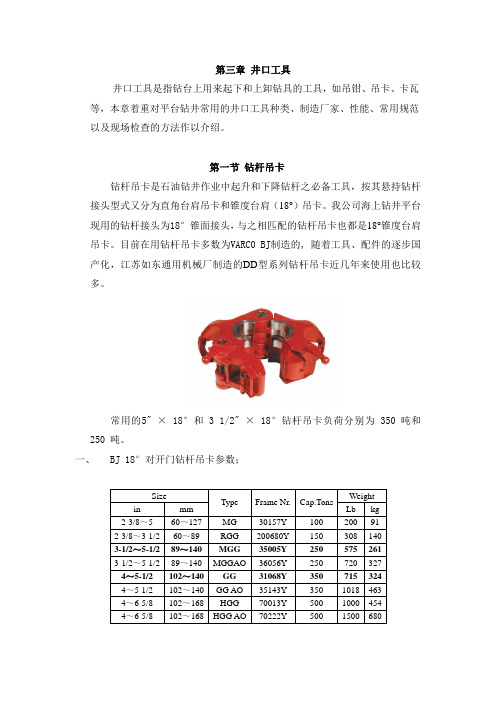
第三章井口工具井口工具是指钻台上用来起下和上卸钻具的工具,如吊钳、吊卡、卡瓦等,本章着重对平台钻井常用的井口工具种类、制造厂家、性能、常用规范以及现场检查的方法作以介绍。
第一节钻杆吊卡钻杆吊卡是石油钻井作业中起升和下降钻杆之必备工具,按其悬持钻杆接头型式又分为直角台肩吊卡和锥度台肩(18°)吊卡。
我公司海上钻井平台现用的钻杆接头为18°锥面接头,与之相匹配的钻杆吊卡也都是18°锥度台肩吊卡。
目前在用钻杆吊卡多数为VARC0 BJ制造的, 随着工具、配件的逐步国产化,江苏如东通用机械厂制造的DD型系列钻杆吊卡近几年来使用也比较多。
常用的5" × 18°和 3 1/2" × 18°钻杆吊卡负荷分别为 350 吨和250 吨。
一、BJ 18°对开门钻杆吊卡参数;二、国产DDZ型为对开式吊卡18度锥台肩钻杆吊卡参数注:锥度吊卡在其型号DD后加注Z,即为DDZ型三、钻杆吊卡检验项目与标准1、装配后活门及销销安全可靠,动作灵活,无卡阻现象。
2、18°锥面的吊卡的锥度不得小于15°。
3、两侧吊耳受力面高度差不大于3.175MM。
4、受力部分探伤检验,润滑部分加油保养,本体除锈刷漆。
5、在用吊卡每年必须探伤检查一次,并记录建档。
四、钻杆吊卡日常保养和检查1、每次起下钻前,应该润滑吊卡的所有活动部位,同时检查锁销、弹簧等所有机械部件工作是否正常。
2、检查铰链销的磨损情况(铰链销的磨损会导致锁销松懈,抱住工具接头时会损坏接头),检查这些部件有无裂纹和大的坑点。
在吊卡使用中,如果铰链销或销紧销松动,就应换下吊卡送到厂家修理。
3、固定吊卡在吊耳内的螺栓应定期更换,现场上必须在螺栓两端拧好螺帽,并经常检查。
第二节吊环吊环是钻柱不可缺少的提升工具,分为单臂吊环,双臂吊环。
一、规格(直径×长度×负荷)1、一般钻柱吊环为直径2-3/4",长108"或132",350吨负荷(吊环的长度是指两受力部位的长度)。
螺杆钻具使用手册(中英文对照版)

1、前言上海奥森油田服务有限公司为渤海石油有限公司(天津)钻井部提供螺杆钻具设备服务,与此同时联同各油田、科研院所,在消化国内外先进技术,结合我国国情的基础上,开发和制造出多种型号的螺杆钻具,能为油田提供满意服务。
本手册主要介绍螺杆钻具的性能和使用要求以及注意事项,便于用户更好地了解我公司的钻具,结合钻井的需要,选好、用好、维护好钻具,发挥其应有的技术性能,提高钻井经济效益。
2.螺杆钻具工作原理螺杆钻具是以泥浆为动力的一种井下动力钻具。
泥浆泵泵出的泥浆液流经旁通阀进入马达,在马达进出口处形成一定压差推动马达的转子旋转,并将扭矩和转速通过万向轴和传动轴传递给钻头。
螺杆钻具的性能主要取决于螺杆马达的性能参数。
3.螺杆钻具的组成螺杆钻具由旁通阀、马达、万向轴和传动轴四大总成组成(如图1)表 1 Table 15LZ165X7。
0Y BH 5LZ165X14。
0 BH q = 8。
5 5LZ197X7。
0Y BH 5LZ197X14。
0 BH q= 14。
0 5LZ120X7。
0Y BH q = 5。
0 5LZ95X7。
0Y BHq = 2.6按以上推荐计算公式,用户可以根据使用需要随时更换不同直径的喷咀,从而达到理想的效果。
Based on the above recommended equation, the customers can timely change different diameter nozzles according to the actual demand, so as to reach ideal effect.3.3 万向轴总成万向轴的作用是将马达的行星运动转变为传动轴的定轴转动,将马达产生的扭矩及转速传递给传动轴至钻头。
万向轴大多采用瓣形,也有采用挠轴形式的。
渤海启明钻具的瓣型万向轴采用线切割技术制成,切口平行度高,粗糙度可达且不破坏金属化学成分,因此使用寿命高、机械损失小(如图4)。
- 1、下载文档前请自行甄别文档内容的完整性,平台不提供额外的编辑、内容补充、找答案等附加服务。
- 2、"仅部分预览"的文档,不可在线预览部分如存在完整性等问题,可反馈申请退款(可完整预览的文档不适用该条件!)。
- 3、如文档侵犯您的权益,请联系客服反馈,我们会尽快为您处理(人工客服工作时间:9:00-18:30)。
TYPE DDZ ELEVATORSMANUAL●Our corporation has passed attestation of API Spec 8CAccredit NO.:API Spec 8C-0159●Our corporation has passed attestation of ISO9001:2008QualitySystem●Certificate NO.:111012032We have the license issued by the Office of the National Industry Product Permitted Production for the Manual Tongs ,Rotary Slips and Elevators.Certificate NO.:XK14-002-00024JIANGSU RUDONG LIANFENG PETROLEUM MACHINERY CO.,LTDAdd :Huaihe Road,New Area of Rudong EconomicDevelopment Zone,Jiangsu ,CHINA Tel :+86-513-84108916,84108108,81906082Fax :+86-513-84108538P.C :226400E-mail:sales@ http ://J i a ng suR u d on gLi an f e ngP et ro le um Ma ch in er yCo .,Lt d .1)Brief Introduction of our product:DDZ 18°degree Drill Pipe Elevator series are important apparatus to control the descending and ascending of the drill pipes in the operation of well-drill or gas-drill or geologicalprospecting.Before the product is used,please read carefully the Usage Instruction.With reasonable design,easy operation,safety and reliability and qualified materials,DDZ 18degree Drill Pipe Elevator series are manufactured by both advanced technology and specialintensity heat treatment.They are verified with super structural and wear-resisting nature bystrict strength test and NDT.They can handle drill pipes of 2.3/8″EU ~65/8″IEUdiameter.The max rating loads of 18degree Drill Pipe Elevator series are 900kN(100tons)、1125kN (125tons )、1350kN(150tons)、2250kN(250tons)、3150kN(350tons)、4500KN(500tons )。
All the technical parameters and properties of the DDZ series elevators are in conformity withthe requirements SY5035and API Spec 8C.2)The composition and their meaning for specifications DDZ 18°degreeDrill Pipe Elevator:D D Z□-□(□-□)Max load (kN)Bore diameter (mm )Max load (US ton)Pipe size and style (inch)Structural Representation :Z means Taper Shoulder Name code:“D”means elevator Type::“D”means center latchJ i a ng suR u d on gLi an f e ngP et ro le um Ma ch in er yCo .,Lt d .3)Structural Principle (See drawing ):The DDZ 18°degree Drill Pipe Elevator is made up of body-left and right ,latch ,latchlock ,hinge pin and springs .The ears of body-left and right can be hung by links .The body left and right are latched by the latch .The body-left and right can be sure not opened by the latch lock when handle drill pipe .All of important parts for the DDZ 18°type elevator are made from high-strength alloy steel .Be sure safety to handle .J i a ng suR u d on gLi an f e ngP et ro le um Ma ch in er yCo .,Lt d .4)Main technical parametersTable 1:Specifications-DDZ 18°type series ElevatorsMark of ElevatorDiameter of bore (mm )Suitable of tool Joint and drill PipeTop BoreBottom Bore Specification of Drill PipeTool Joint DesignationReferenceDDZ23/8EU-()107.9567.4723/8EU NC26(2.3/8IF)DDZ27/8EU-()120.6583.3427/8EU NC31(2.7/8IF)DDZ31/2EU-()139.70100.8131/2EU NC38(3.1/2IF)orNC40(4IF)DDZ4IU-()165.10108.744IU NC40(4FH)DDZ4EU-()171.45121.444EUNC46(4IF)DDZ41/2IU-()41/2IUNC46(4IF)or4.1/2FHDDZ41/2IEU-()41/2IEUNC46(4IF)or4.1/2FH DDZ41/2EU-()180.98133.3541/2EUNC50(4.1/2IF)DDZ5IEU-()5IEUNC50(4.1/2IF)or5.1/2FHDDZ51/2IEU-()200.02147.6451/2IEU 5.1/2FH DDZ57/8IEU-()20015757/8IEU 57/8FH DDZ65/8IEU-()225178.5965/8IEU65/8FHREMARKS :1、IU means internal upset drill pipe,EU means external upset drill pipe,IEU means internal and external upset drill pipe2、Bracket-filled are the max rating loadTable 2:Rated capacities-DDZ 18°type series ElevatorsRated capacitieskN90011251350225031504500tons 100125150250350500Suitable for Drillpipe Size (O.D )in 2.3/8~52.3/8~5.1/23.1/2~5.1/24-5.1/24~6.5/8Min.and Max.Dia.weld less Linksin 1.3/4~2.3/4 2.1/4~3.1/2 2.1/4~3.1/2 3.1/2~4.3/4mm44.45~69.8557.15~88.957.15~88.988.9~120.6J i a ng suR u d on gLi an f e ngP et ro le um Ma ch in er yCo .,Lt d .5)Usage and Operation●The DDZ type elevator is suitable to single elevator lifting and dropping pipes in thework of well drilling.●Overload is strictly forbidden.The elevator should be operated at not less than -20℃.●Before use,please check the opening and closing flexibility of the latch and the latch lock,and their ability whether are reliable.Twisting force of the spring should be proper.●After a period of use or the maintenance of the elevator,the bodies and latch should bestrictly examined.It is not allowed to use any more in case of any defects such as cracksand deformation.And it is not allowed to use if the latch lock can ,t be blocked by thesafety pin.●Before every lifting and dropping drill tools,should be check whether the hinge pin and etc.are normal or not.Check them whether excessively wear and tear and clear weaken.The surface of hinge pin and the places in contact with links should be greased.●Check and mature the cone bore of the DDZ type elevator and the surface of dill pip joint in cooperation with the elevator.When wearing isn ,t even or sunken up to more than 1.5mm.It should be repaired.J i a ng suR u d on gLi an f e ngP et ro le um Ma ch in er yCo .,Lt d .6)Deduction of wear and tearBefore use,check carefully the taper of the elevator and drill pipe joint.See whole loaded surface whether take place change.If happen,should reconsider rated capability of elevator according to above the table or deliver back our company to repair.Overload is strictlyforbidden.J i a ng suR u d on gLi an f e ngP et ro le um Ma ch in er yCo .,Lt d .7)Maintenance●Fitting grease to turning round and sliding places of the elevator.●Be sure do not drop the elevators from higher position.●After use,clean oil dirt and mud at elevator,and coat antirust grease,and put it at dryplace in house.●After a period of use,remove paint away form the forced place of the bodies,the latchand etc.and undergo flaw detection inspection.It is not allowed to use any more in caseof any defects such as scars or cracks.NDT elevators after each drilling operation andrecord the test results.When crack is found,the elevator can not be used.●For the usage and maintenance of the elevator,place refer to SY/T6100-1994-Usage andMaintenance for oil Drilling and Production Hoisting Equipment.●The elevator must not be welded and repaired without thetechnical information of our corporation.In case the repairingfactory conduct strict and proper maintenance and inspection in conformitywithstandardNO.SY/T6100-94“Elevatingequipment use and maintenance of oil drilling and exploring”,SY/T 6357-1998“program of inspection,maintenance,repairing and restoring of theelevating equipment”,and API RP 8B “recommended process of inspection and maintenance of the elevator”,the elevator can be welded or repaired.8)Transportation and StorageCrash is strictly forbidden when in transportation of the elevators.It must be prevented from rain during transportation.The product must be stored in the dry and well ventilated places,and prevented from in the sun or in the rain.It’s forbidden to let products contact acids,alkalis and other corrosive substance.J i a ng suR u d on gLi an f e ngP et ro le um Ma ch in er yCo .,Lt d .No.DESCRIPTIONQTY.1LEET BODY 12LATCH 13LATCH PIN*14CIRCLIP FOR HOLE*15LATCH SPRING*16LATCH SPRING STOP 17LATCH LOCK SPRING*18LATCH LOCK BOLT*19LATCH LOCK110RIGHT BODY 111LINK BLOCK*212NUT*213COTTER PIN*314LATCH LOCK BOLT NUT*315BOLT*216GREASE FITTING*117DOOR CATCH ARM 118DOOR CATCH ARM PIN 119ROOLER 120ROOLER PIN121DOOR CATCH SPRING 122BOLT*223CIRCLIP FOR HOLE*124HINGE PIN*1*WEARING PARTSJ i a ng suR u d on gLi an f e ngP et ro le um Ma ch in er yCo .,Lt d .。