智能控制翻译
人工智能的实现方法

人工智能的实现方法一、人工智能的基本概念人工智能(Artificial Intelligence,简称AI)是指通过计算机模拟人类智能的理论、方法、技术和应用系统。
它是计算机科学、信息科学、数学、心理学等多个学科交叉发展而成的新兴领域,旨在让计算机具备类似人类的感知、思考、决策和行动能力。
二、人工智能的实现方法1. 机器学习机器学习(Machine Learning)是一种让计算机自主获取知识和技能的方法。
它通过对大量数据进行分析和处理,从中提取规律和特征,并将这些经验性知识应用到新的问题中。
常见的机器学习算法包括决策树、支持向量机(SVM)、神经网络等。
2. 深度学习深度学习(Deep Learning)是一种基于神经网络模型的机器学习方法。
它通过多层次的神经元连接构建复杂的非线性模型,并使用反向传播算法进行训练和优化。
深度学习已经在图像识别、语音识别等领域取得了重大突破。
3. 自然语言处理自然语言处理(Natural Language Processing,简称NLP)是一种让计算机理解和处理人类语言的技术。
它涉及到文本分析、语义理解、信息抽取等多个方面,可以用于机器翻译、智能客服、情感分析等应用。
4. 机器视觉机器视觉(Computer Vision)是一种让计算机模拟人类视觉系统的技术。
它可以从图像或视频中提取出有用的信息,并进行分析和识别。
常见的应用包括人脸识别、车牌识别、物体检测等。
5. 专家系统专家系统(Expert System)是一种基于知识库和推理引擎的人工智能应用。
它通过收集领域内专家的知识和经验,建立起一个规则库,并使用推理引擎来解决问题。
专家系统可以应用于医疗诊断、金融分析等领域。
6. 智能控制智能控制(Intelligent Control)是一种基于人工智能技术实现自主控制的方法。
它可以根据环境变化和目标要求,自主调整行为策略和决策,实现自适应控制和优化控制。
智能控制可以应用于自动驾驶、智能家居等领域。
外文翻译--农业温室大棚智能自动化控制

毕业设计论文外文资料翻译学院:电气学院专业:电气工程及其自动化姓名:学号:外文出处:Agricultural greenhousesgreenhouse intelligent automaticcontrol附件: 1.外文资料翻译译文;2.外文原文。
附件1:外文资料翻译译文农业温室大棚智能自动化控制摘要:历来确定的轨迹到controlgreenhouse农作物生长的问题解决了用约束优化或应用人工智能技术。
已被用作经济利润的最优化研究的主要标准,以获得充足的气候控制设定值,为作物生长。
本文讨论了通过分层控制体系结构由一个高层次的多目标优化方法,要解决这个问题是要找到白天和夜间温度(气候相关的设定值)和电导率的参考轨迹管辖的温室作物生长的问题( fertirrigation的相关设定值)。
的目标是利润最大化,果实品质,水分利用效率,这些目前正在培育的国际规则。
在过去8年来,获得在工业温室的选择说明结果显示和描述关键词分层农业;系统,过程控制,优化方法;产量优化1。
介绍现代农业是时下在质量和环境影响方面的规定,因此,它是一个自动控制技术的应用已在过去几年增加了很多([法卡斯,2005和Sigrimis,2000] [Sigrimis 等。
,2001],[Sigrimis和国王,1999]和Straten等。
,2010])。
温室生产agrosystem的是一个复杂的物理,化学和生物过程,同时发生,反应不同的响应时间和环境因素的模式,特点是许多相互作用(Challa及Straten,1993年),必须以控制种植者获得最好的结果。
作物生长过程是最重要的,主要是由周围环境的气候变量(光合有效辐射PAR - ,温度,湿度,和内空气中的二氧化碳浓度)的影响,水和化肥,灌溉,虫害和疾病提供的金额,如修剪和处理他人之间的农药和文化的劳动力。
温室是理想的增长,因为它构成一个封闭的环境,气候和fertirrigation变量在可控制的作物。
专家控制系统

1、什么是专家系统?它具有哪些特点和优点?1)专家系统:专家系统(Expert System)是一种在特定领域内具有专家水平解决问题能力的程序系统,其内部含有大量的某个领域专家水平的知识与经验,能够利用人类专家的知识和解决问题的经验方法来处理该领域的高水平难题。
也就是说,专家系统是一个具有大量的专门知识与经验的程序系统,它应用人工智能技术和计算机技术,根据某领域一个或多个专家提供的知识和经验,进行推理和判断,模拟人类专家的决策过程,以便解决那些需要人类专家才能处理好的复杂问题。
简而言之,专家系统是一种模拟人类专家解决领域问题的计算机程序系统。
2)专家系统的特点:①启发性:专家系统要解决的问题,其结构往往是不合理的,其问题求解知识不仅包括理论知识和常识,而且包括专家本人的启发知识;②透明性:专家系统能够解释本身的推理过程和回答用户提出的问题,以便让用户了解推理过程,增大对专家系统的信任感;③灵活性:专家系统的灵活性是指它的扩展和丰富知识库的能力,以及改善非编程状态下的系统性能,即自学习能力;④符号操作:与常规程序进行数据处理和数字计算不同,专家系统强调符号处理和符号操作(运算),使用符号表示知识,用符号集合表示问题的概念。
一个符号是一串程序设计,并可用于表示现实世界中的概念;⑤ 不确定性推理:领域专家求解问题的方法大多数是经验性的,经验知识一般用于表示不精确性并存在一定概率的问问题。
止匕外,所提供的有关问题的信息往往是不确定的。
专家系统能够综合应用模糊和不确定的信息与知识,进行推理;⑥为解决特定领域的具体问题,除需要一些公共的常识,还需要大量与所研究领域问题密切相关的知识;⑦ 一般采用启发式的解题方法;⑧在解题过程中除了用演绎方法外,有时还要求助于归纳方法和抽象方法;⑨需处理问题的模糊性、不确定性和不完全性;⑩能对自身的工作过程进行推理(自推理或解释);11采用基于知识的问题求解方法;12知识库与推理机分离。
【机械类文献翻译】对移动式遥控装置的智能控制—使用2型模糊理论

附件1:外文资料翻译译文对移动式遥控装置的智能控制——使用2型模糊理论摘要:我们针对单轮移动式遥控装置的动态模型开发出一种追踪控制器,这种追踪控制器是建立在模糊理论的基础上将运动控制器和力矩控制器整合起来的装置。
用计算机模拟来确定追踪控制器的工作情况和它对不同航向的实际用途。
关键词:智能控制、2型模糊理论、移动式遥控装置I. 介绍由于受运动学强制约束,移动遥控装置是非完整的系统。
描述此约束的恒等式不能够明确的反映出遥控装置在局部及整体坐标系中的关系。
因此,包括它们在内的控制问题吸引了去年控制领域的注意力。
不同的方法被用来解决运动控制的问题。
Kanayama等人针对一个非完整的交通工具提出了一个稳定的追踪控制方案,这种方案使用了Lyapunov功能。
Lee等人用还原法和饱和约束来解决追踪控制。
此外,大多数被报道过的设计依赖于智能控制方式如模糊逻辑控制和神经式网络。
然而上述提到的发表中大多数都集中在移动式遥控装置的运动模块,即这些模块是受速度控制的。
而很少有发表关注到不完整的动力系统,即受力和扭矩控制的模块:布洛克。
在2005年12月15日被视为标准并且在2006年3月5日被公认的手稿。
这一著作在某种程度上受到DGEST——一个在Grant 493.05-P下的研究所的支持。
研究者们同样也受到了来自CONACYT——给予他们研究成果的奖学金的支持。
在这篇论文中我展现了一台追踪单轮移动式遥控装置的控制器,这台追踪控制器用了一种控制条件如移动遥控装置的速度达到了有效速度,还用了一种模糊理论控制器如给实际遥控装置提供了必要扭矩。
这篇论文的其余部分的结构如下:第二部分和第三部分对问题作了简洁描述,包括了单轮车移动遥控装置的运动和动力模块和对追踪控制器的介绍。
第四部分用追踪控制器列举了些模拟结果。
第五部分做出了结论。
II. 疑难问题陈述A 移动控制装置这个被看作单轮移动控制器的模型(见图1),它是由两个同轴驱动轮和一个自由前轮组成。
自动化专业常用英语词汇
自动化专业常用英语词汇引言概述:自动化专业作为现代工程技术领域的重要学科,涵盖了广泛的知识和技能。
在学习和实践中,掌握一些常用的英语词汇对于自动化专业的学生来说至关重要。
本文将介绍自动化专业常用的英语词汇,帮助读者更好地理解和应用于实践中。
一、控制系统(Control Systems)1.1 控制器(Controller):负责监测和调整系统的行为,以实现预期的目标。
1.2 传感器(Sensor):用于检测和测量物理量,将其转化为电信号,以便于控制器的处理。
1.3 执行器(Actuator):根据控制器的指令,执行相应的动作,从而实现对系统的控制。
二、自动化设备(Automation Equipment)2.1 机器人(Robot):能够自主执行任务的自动化设备,通常具备感知、决策和执行能力。
2.2 传送带(Conveyor):用于将物体从一个位置运输到另一个位置的自动化设备。
2.3 自动化装置(Automation Device):用于自动完成特定任务的设备,如自动装配线、自动化仪器等。
三、控制策略(Control Strategies)3.1 开环控制(Open-loop Control):根据预先设定的输入信号,直接控制执行器的动作,而不考虑系统的反馈信息。
3.2 闭环控制(Closed-loop Control):根据系统的反馈信息,调整控制器的输出信号,以实现对系统的精确控制。
3.3 模糊控制(Fuzzy Control):基于模糊逻辑理论,将模糊的输入转化为模糊的输出,用于处理复杂的非线性系统。
四、通信协议(Communication Protocols)4.1 以太网(Ethernet):一种常用的局域网通信协议,用于实现设备之间的数据传输和通信。
4.2 控制网(ControlNet):一种用于工业自动化领域的网络通信协议,支持实时数据传输和设备控制。
4.3 无线通信(Wireless Communication):通过无线信号进行数据传输和通信的技术,如Wi-Fi、蓝牙等。
外文翻译---一种新型的液压锻造操作机的智能控制

附录(二)原文:Intelligent Control of a Novel Hydraulic Forging Manipulator AbstractThe increased demand for large-size forgings has led to developments and innovations of heavy-duty forging manipulators. Besides the huge carrying capacity, some robot features such as force perception, delicacy and flexibility, forging manipulators should also possess. The aim of the work is to develop a heavy-duty forging manipulator with robot features by means of combination of methods in mechanical, hydraulic, and control field. In this paper, through kinematic analysis of a novel forging manipulator, control strategy of the manipulator is proposed considering the function and motion of forging manipulators. Hybridpressure/position control of hydraulic actuators in forging manipulator is realized. The feasibility of the control method has been verified by the experiments on a real prototype of the novel hydraulic forging manipulator in our institute. The intelligent control of the forging manipulator is performed with programmable logic controller which is suitable for industrial applications.1.IntroductionThe use of manipulators in open die or free forging can be traced back about 60 years when development started in both Europe and the USA. Manipulators for heavy workpieces, that is, those in the region of 200 tons weight, have been developed steadily since that time, and currently there are a number of examples of computer-controlled fully automatic forging manipulators being used . As a result of the practical use of the control system, the operators were released from mental stress, the training period for operators was reduced, the uniformity of forging quality was improved, and a higher production rate was attained .Control of the manipulators involves rotational control in the continuous rotation and incremental angle rotation modes. The manipulator position requires integrated control with the press to achieve inches per press stroke while compensating for workpiece length increase due to cross-section area reduction ofworkpiece . Vitscheff demonstrates the need for compliance control when robots are used to manipulate the workpiece during forging. Specifically, the external forces exerted on the manipulator through its manipulation of the workpiece during forging steps must be minimized to avoid damage to the robot mechanism.An ASEA robot was used as an open-die forging manipulator. The ASEA robot has an inbuilt Intel microprocessor which controls its arm and gripper movements in five axes. The robot was used in conjunction with a fielding hydraulic press . The application of neural networks for compliance control of the forging robot was investigated. Effectiveness of the neural network-based compliance control module is evaluated through a full dynamic system simulation . An integrated forging plant, 25 MN open die press with 200 kN and 400 kNm manipulators, was built in 1999. The workpiece is put into position by two rail-bound manipulators with rotation and travel movements actuated by closed hydraulic circuits to reduce energy consumption and shocks and to improve positioning . The rail-bound forging manipulator with a carrying capacity of 1600 kN and 4000 kNm load moment started its operation in 2007 at JSW. The manipulator supports a straight line peel movement as well as an accurate and stable positioning which is possible because of the special lever arrangement .The increased demand for large-size forgings has led to developments and innovations all around the improvement of quality and productivity. Many efforts have been undertaken to research and develop heavy-duty forging manipulators. The researches in recent years focus on the mechanisms of forging manipulator, such as kinematic modeling and analysis ; dynamic load analysis, dynamic stability, and behavior ; performance analysis and optimization .The forging manipulator is not only an equipment with huge carrying capacity, but also a robot with delicacy and flexibility, capable of picking up and putting down workpieces gently with force perception. The compliance is another required capability of heavy-duty forging manipulators. It is important of the promotion of quality, protection of manipulator, reduction of impact of heavy load, and energy saving. The overall aim of this work is to develop a heavy-duty forging manipulator with robot features by means of combination of methods in mechanical, hydraulic, and control field. The kinematic analysis of a novel forging manipulator is performed. On this basis, control strategy of the manipulator is proposed considering the function and action of forging manipulators. Hybrid pressure/position control ofhydraulic actuators in forging manipulator is realized. The control of a real prototype of the novel hydraulic forging manipulator in our institute reaches the target of intelligent control.2. Model of Control ObjectThis work focuses on the novel track-mounted forging manipulator used for heavy-duty manipulations in integrated open-die forging plants. This serial-parallel forging manipulator is newly designed in our institute. Its CAD model is shown in Figure 1.Figure1: CAD model of the serial-parallelforging manipulator.3. Control StrategyThe whole forging process can be divided into three stages of prepress, inpress, and afterpress. During the periods of prepress and afterpress, operations of the forging manipulator are the same: the gripper grasps the workpiece then places it on the lower die. During the period of inpress, the forging manipulator complies with the deformation of the workpiece. The control strategy of forging manipulator in these three conditions is discussed as follows.(a) Grasp the WorkpieceFirstly, the horizontal and vertical position of the gripper is adjusted, and the workpiece on the bench is clamped by the gripper. Then the workpiece is lifted up by lifting cylinders with a constant lifting force which is greater than the total weight of the workpiece, gripper, and its support. When the expected height is exceeded, the position error will feed back to the constant force servosystem of lifting cylinders. This negative feedback of position makes the actual lifting force smaller than the setting value. In equilibrium, the actual lifting force equals the total weight of the workpiece, gripper, and its support, and the error of force equals the error of position multiplied a coefficient.The workpiece is fed to the forging press, right over the lower die by the forging manipulator. Then decreasing the height setting value, the balance of force and position of lifting cylinders is broken. The actual lifting force is smaller than the total weight of the workpiece, gripper, and its support. So the workpiece moves down with the gripper. The decent velocity of the workpiece is determined by the change rate of the height setting value. When the workpiece touches the lower die, the pressure in lifting cylinders will change greatly for the workpiece begins to be supported by the lower die. At this moment, keeping the height setting value constant, then the force and position of lifting cylinders comes to a new balance.(c) Comply with the WorkpieceDuring forging, when the workpiece is pressed by the upper die, extra force is applied on the gripper by the deformed workpiece. The force causes an increase of the load in lifting cylinders. Meanwhile, the servosystem is trying to keep the lifting force constant. As a result, the gripper moves down with the workpiece and applies the minimum reaction force on the deformed workpiece. When press is over, the upper die rises, and the external force exerted on the gripper disappears. The workpiece is lifted up to the original position by a constant lifting force. Then the manipulator carries the workpiece to feed. The next press is ready.As discussed above, hybrid force/position control is the core principle in forging manipulator control. Figure 2 illustrates the hybrid control system that incorporates these ideas. Force control is the base of the control loop. In the balanced state, expect that the actual lifting force is equal to the weight of the workpiece, gripper, and its support, smaller than the force setting value. The error of force should be compensated by another control variable. The negative feedback of error of position is added to the control loop. When the actual lifting position is lower than the height setting value, the feedback of error of position is zero, and the gripper moves up under a constant lifting force. When the actual lifting position is higher than the height setting value, the negative feedback of error of position works, and the actual lifting force decreases until force and position tends to balance.Figure 2: Construct of the hybrid controlsystem.Owing to the newly designed mechanism of the forging manipulator which is decoupled as discussed in Section 2, the motions of side shifting, tilting, damping, and lifting are independent, and any one of the motions has no effect on the others. The control of the forging manipulator is simplified and only related to lifting cylinders. During the whole period of forging process, front side-shifting cylinders, rear side-shifting cylinders, and tilting cylinders keep their positions all the time. The deformation of workpiece in horizontal direction is absorbed by damping cylinders during the process of inpress. The compliance happens when the deformation resistance is larger than the setting value of pressure relief valve in damping hydraulic circuit. The reaction force in horizontal direction almost keeps constant that depends on the property of the relief valve.4. Pressure/Position Control Method of Hydraulic ServosystemA block diagram of the overall control scheme is shown in Figure3. The system is composed of controller, power amplifier, servovalve, cylinder, pressure sensor, and position sensor.Figure 3: Block diagram ofhybrid pressure/position controlsystem.Hybrid pressure/position control is very useful in manipulator lifting control where plunger cylinders are used. Based on this method, the intelligent control of forging manipulator is realized.5. Analysis of Intelligent Control5.1. Automatic Identification of Pressure Value SettingsAs shown in Figure 4, when the workpiece is grasped by the manipulator, the hybrid pressure/position control method is used, and the pressure and position command values are set with original ones of P0 and X0. The workpiece is lifted up with a constant force created by hybrid control loop with command pressure P0. When the position command value X0 is exceeded, the negative position error feeds back to the pressure control loop, the actual pressure in system begins to decrease and will stop decreasing at the weight balance pressure. In equilibrium, the workpiece stops moving, and the actual lifting force equals the total weight of the workpiece, gripper, and its support. Record this actual balance pressure and use it as the pressure value settings in compliance control in forging process.Figure 4: Illustration of the measurement ofworkpiece.5.2. Automatic Identification of the Placement Height of WorkpieceAs shown in Figure 5, supposing the workpiece is staying at a position with equilibrium of forces, decrease the command position X0 in a constant rate, then the balance has been broken. For the feedback of error of position increasing, the actual pressure will become smaller and try to go to another equilibrium state. The actual lifting force is less than the weight of the workpiece, gripper, and its support now. So the workpiece moves down until touching the lower die. At this moment, the actual pressure drops rapidly. According to the change rate of pressure, the workpiece placement state can be identified automatically. Keep the command position X0 with the height value of workpiece position placed on the lower die. The pressure and position of lifting cylinders goes to a new balance.Figure5: Illustration of the placement ofworkpiece.5.3. Compliance in Vertical Direction and Move Up AutomaticallyAs shown in Figure 6, when the workpiece is pressed by the upper die, the load on cylinder will increase for the deformation of workpiece; this process is called “inpress.” In the mode of pressure/position control, the increased load makes the workpiece move down, and when X < X0, the position error feed back does not work. During this period, the force acting on the workpiece by manipulator increases from weight balance pressure to the command pressure P0, while it is still much smaller than the press force. Thus, the compliance in vertical direction is realized. When press is finished and upper die moves up, this process is called “afterpress,” the load on cylinder decreases. The lifting force makes the workpiece move up until the pressure and position of lifting cylinders goes to a new balance.Figure 6: Illustration of the complianceduring forging steps.6. Experiment ResultsThe experiments were executed on a real prototype of the novel hydraulic forging manipulator in our institute, as shown in Figure 7. The mechanism and hydraulic system of the manipulator is identical with a rail-bound forging manipulator with a carrying capacity of 2000 kN and 4000 kNm load moment which is designed by our institute. The main characteristics of this prototype are carrying capacity60 kN, load moment 150 kNm, and installed power 130 kW. The hydraulic actuators are supplied by a constant pressure pump source and controlled by servoproportional valves with position transducer. A programmable logic controller performs all control actions.Figure 7: Prototype of the novel hydraulicforging manipulator.Figure 8 demonstrates the measurement of the weight and the gravitational torque of workpiece. The controller attempts to maintain a constant pressure4.2 MPa, and while the height of the workpiece position exceeds the preset command position 400 mm, the negative feedback of position works. When lifting cylinders stop moving, control returns to a stable steady state. The weight-balanced pressure can be identified from the curve, which is 3.55 MPaFigure 8: Pressure curve in lifting cylinder.Figure 9 depicts the process of placing the workpiece on the lower die. While the command position signal diminished at a constant rate, the workpiece moved down trying to catch the rate. The touch of workpiece on the lower die can be detected by pressure changes in lifting cylinders. Lifting cylinders stayed on this position. The height of the workpiece placement can be found from the curve.Figure 9: Position curve in lifting cylinder.The experiment results show that the technique is straightforward and feasible. All the supposed control methods have been realized on the prototype of the forging manipulator. The experimental datum forms the base of furtherresearch on intelligent control of heavy-duty forging manipulators.7. ConclusionsA novel hydraulic forging manipulator is proposed, with newly designed mechanism, intelligent control strategy, and improved hydraulic control method. Themajor motion mechanism is decoupled, thus the control of the forging manipulator is greatly simplified. Workpieces can be picked up and put down gently by forgingmanipulators with force perception. Moreover, the forging manipulator can comply with the external forces exerted on it by workpiece during forging steps. These are based on a new pressure control method and a hybrid pressure/position controlmethod of hydraulic servosystem presented in this paper. All of the hydraulic control methods and intelligent control strategies have been verified by experiments on the prototype forging manipulator. This work provides the theoretical and practicalfoundation for further development of intelligent heavy-duty forging manipulators.References1. E. Appleton, W. B. Heginbotham, and D. Law, “Open di e forging with industrialrobots.,”Industrial Robot, vol. 6, no. 4, pp. 191–194, 1979. View at Scopus2.“Attaining practicality of freely programmable control of an open die forging press and forgingmanipulator by a computer,” Ishikawajima-Harima Engineering Review, vol. 17, no. 6, pp.599–606, 1997.3.R. A. Ridgeway, “Microprocessor utilization in hydr aulic open-die forge press control,” IEEETransactions on Industrial Electronics and Control Instrumentation, vol. 22, no. 3, pp. 307–309, 1975. View at Scopus4.V. Vitscheff, “A programmable manipulator for closed die forging,” in Proceedings of the 9thInternational Drop Forging Convention, Kyoto, Japan, 1977.5.W. B. Heginbotham, A. K. Sengupta, and E. Appleton, “An ASEA robot as an open-die forgingmanipulator,” in Proceedings of the Second IFAC/IFIP Symposium, pp. 183–193, Stuttgart, Germany, 1979.6. A. K. Sengupta, E. Appleton, and W. B. Heginbotham, “Ring forging with an industrial robot,”inProceedings of the 10th International Symposium on Industrial Robots, pp. 29–42, Milan, Italy, 1980.7.K. W. Lilly and A. S. Melligeri, “Dynamic simulation and neural network compliance control ofan intelligent forging center,” Journal of Intelligent and Robotic Systems, vol. 17, no. 1, pp. 81–99, 1996. View at Scopus8. A. S. Melligeri and K. W. Lilly, “Application of neural networks in compliance control of anintegrated robot/forge processing center,” in Advances in Manufacturing Systems: Design, Modeling and Analysis, pp. 445–450, Elsevier, New York, NY, USA, 1993.9.M. Baldassi, “Open die forging presses with manipulators,” Forging, vol. 14, no. 5, pp. 16–18,2003.译文:一种新型的液压锻造操作机的智能控制摘要大尺寸锻件的需求增加,导致重型锻造机械手的发展和创新。
控制工程基础论文
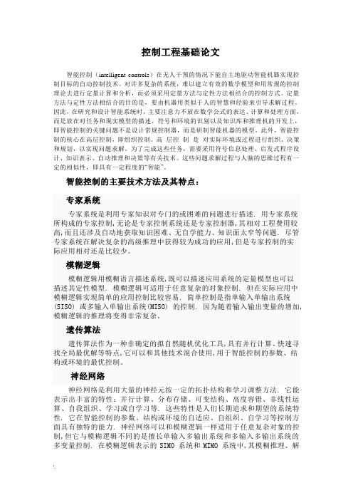
控制工程基础论文智能控制(intelligent controls)在无人干预的情况下能自主地驱动智能机器实现控制目标的自动控制技术。
对许多复杂的系统,难以建立有效的数学模型和用常规的控制理论去进行定量计算和分析,而必须采用定量方法与定性方法相结合的控制方式。
定量方法与定性方法相结合的目的是,要由机器用类似于人的智慧和经验来引导求解过程。
因此,在研究和设计智能系统时,主要注意力不放在数学公式的表达、计算和处理方面,而是放在对任务和现实模型的描述、符号和环境的识别以及知识库和推理机的开发上,即智能控制的关键问题不是设计常规控制器,而是研制智能机器的模型。
此外,智能控制的核心在高层控制,即组织控制。
高层控制是对实际环境或过程进行组织、决策和规划,以实现问题求解。
为了完成这些任务,需要采用符号信息处理、启发式程序设计、知识表示、自动推理和决策等有关技术。
这些问题求解过程与人脑的思维过程有一定的相似性,即具有一定程度的“智能”。
智能控制的主要技术方法及其特点:专家系统专家系统是利用专家知识对专门的或困难的问题进行描述. 用专家系统所构成的专家控制,无论是专家控制系统还是专家控制器,其相对工程费用较高,而且还涉及自动地获取知识困难、无自学能力、知识面太窄等问题. 尽管专家系统在解决复杂的高级推理中获得较为成功的应用,但是专家控制的实际应用相对还是比较少。
模糊逻辑模糊逻辑用模糊语言描述系统,既可以描述应用系统的定量模型也可以描述其定性模型. 模糊逻辑可适用于任意复杂的对象控制. 但在实际应用中模糊逻辑实现简单的应用控制比较容易. 简单控制是指单输入单输出系统(SISO) 或多输入单输出系统(MISO) 的控制. 因为随着输入输出变量的增加,模糊逻辑的推理将变得非常复杂。
遗传算法遗传算法作为一种非确定的拟自然随机优化工具,具有并行计算、快速寻找全局最优解等特点,它可以和其他技术混合使用,用于智能控制的参数、结构或环境的最优控制。
Intelligent lighting control system(智能照明控制系统) 外文翻译

Intelligent lighting control systemAbstract: Intelligent lighting control system the main aim is to save energy, smart lighting control system with a variety of "pre-set" control mode and control components, at different times on different degrees of illumination for accurate set-up and rational management of energy-saving. This automatic adjustment of the illumination means, take full advantage of the natural outdoor light, only when necessary when the lamp or light to the required brightness, use the least energy to ensure that the required illumination level, energy-saving effect is very clear, usually ranging from more than 30%.Keywords: Intelligent lighting control system bus-type star-shaped structure1 the use of intelligent lighting control system for the superiority of1.1 good energy saving effectIntelligent lighting control system using the main purpose is to save energy, smart lighting control system with a variety of "pre-set" control mode and control components, at different times on different degrees of illumination for accurate set-up and rational management of energy-saving. This automatic adjustment of the illumination means, take full advantage of the natural outdoor light, only when necessary when the lamp or light to the required brightness, use the least energy to ensure that the required illumination level, energy-saving effect is very clear, usually ranging from more than 30%. In addition, the intelligent lighting control system for fluorescent lamp dimming control, etc., due to the use of a fluorescent active tunable filter electronic ballast technology and reduce the harmonic content, to improve the power factor and reduce the low-voltage reactive power loss.1.2 to extend the life span of light sourceLight source can not only extend the life savings, but also significantly reduce the workload of lamp replacement, reducing the operating costs of lighting systems, management and maintenance becomes simple.Both the thermal radiation source, or gas discharge light source, voltage fluctuations are a major cause of light damage. Therefore, the effective suppression of the fluctuations in voltage can extend the life of light sources.Intelligent lighting control system can successfully suppress the surge voltage power grid, but also have a voltage limit and the conjugate stream functions of filtering, to avoid over-voltage and under-voltage damage to the light. The use of soft-start and soft turn-off technology, to avoid the impact of current damage to the light. Through this method, the light source to extend the life span of usually 2 to 4 times.1.3 to improve the working environment, improve efficiencyGood working environment is to improve the efficiency of a necessary condition. Good design and reasonable choice of light source, lamps and lighting quality control systems, can improve the quality of lighting.Intelligent lighting control system dimming control panel module to replace the traditional lighting of the level switch control is an effective way to control the overall room illumination value, thereby enhancing the uniformity of illumination. At the same time, this control method used in electrical components have also solved the stroboscopic effect, will not create uncomfortable, confused, feeling eyestrain.1.4 to achieve a variety of lighting effectsA wide range of lighting control, the same building can have a variety of artistic effect, for a lot of construction hyperchromic. Modern buildings, lighting is not simply to meet people on the visual effect of light and shade, they should have control of a variety of programs to make buildings more vivid, more artistic, giving a wealth of visual effects and aesthetics. As an example of a project, building the exhibition hall, lecture hall, lobby, atrium, etc., if with intelligent lighting control system, according to different times, different uses, different effects, using the corresponding pre-set scene control, can achieve the wealth of artistic effect.1.5 facilitate the management of maintenanceIntelligent lighting control system for the control of lighting based on the automatic control of modular-based, supplemented by manual control, preset lighting scenes to the parameters stored in the EPROM Digital, these information is very convenient to set up and replaced, so that building lighting management and maintenance easier.1.6 have a high economic rate of returnOur reference point for the Shanghai region, from energy-saving lights and provincial estimates of the two made a come to this conclusion: with three to five years, the owner can recover the basic intelligent lighting control system to increase the total costs. Intelligent lighting control system can improve the environment and improve employee productivity and reduce maintenance and management costs, but also for the owners to save a substantial amount of costs.2 intelligent lighting control system componentsWe know that the intelligent lighting control system of building control system is only one part of the. If you want to focus on the various control systems to the control center to control, then the control system must have the standard communication interface and protocol version. Although such a system integration is feasible in theory, but it is very difficult to put into practice. Thus, in engineering, intelligent management of our building a distributed system, distributed, that is relatively independent of each control subsystem, self-contained, the implementation of specific control, intelligent building management system control subsystem of the relative independence, self-contained, the implementation of specific control, intelligent building management system from the control subsystem is a signal collection and monitoring role.At present, the intelligent lighting control system in accordance with sub-network topology, the following two forms, namely, bus and star-shaped structure-based hybrid. Both forms have the characteristics of a number of bus more flexibility, easy expansion, control of relative independence, lower costs; mixed some high reliability, fault diagnosis and rule out the simple, easy access to the agreement, transfer rate higher.Engineering design, we consider the building of intelligent lighting control system as an independent subsystem, use of international standards and agreements of the communication interface text, into the intelligent building management systems. Intelligent lighting control system uses a distributed, distribution-based approach, that is, the dimming control unit is relatively independent, self-contained, non-interfering, through centralized management and information interfaces, and intelligent building managementsystem linked to the achievement of the building control center subsystem of the collection and monitoring of the signal. In short, the intelligent lighting control should be the main system is a centralized management, and the main trunk and information interface components consisting of the regional implementation of the same sample of control and signal networks; its subsystems should be a dimmer by the various types of modules , control panels, illumination detector dynamic and static and dynamic components consisting of detectors, respectively, of the regional implementation of the specific control of different networks, the main system and subsystems, such as between the components through the interface to connect, to achieve data transmission.3 Intelligent lighting control system and control of the control of the contentA project to control the use of intelligent lighting control system include the following categories: technology office hall, computer center and other important room, lecture hall, such as multi-function hall, exhibition hall, conference center, lobby and courtyard, walkways and elevators, such as the Office of Public site; building facade lighting in general and also by the intelligent lighting control systems to control switch signal.Control the content of the term of the Interpretation:(1) clock controlClock management, etc. through the electrical components, to achieve the normal work of regions for the state of lighting in different time control.(2) the automatic adjustment control illuminationThrough each module and illumination dimming dynamic electrical components such as detectors, to achieve under normal conditions in the regions for the normal work of the state of the automatic lighting dimming control, making the region, such as illumination will not be outside with the sunshine factors change, and always maintain the default value in the illumination around.(3) control of the regional sceneThrough each dimmer module and the control panel and other electrical components, to achieve under normal conditions in the regions for the normal work of the state of the scene lighting control switch.(4) static and dynamic detection of controlThrough each dimming modules and electrical components, such as movement detectors, to achieve under normal conditions in the regions for the normal work of the state of the automatic lighting control switch.(5) Reduction state of emergency controlThrough each of the normal lighting control module, such as dimming of the electrical components, to achieve a state of emergency for the normal work of the various districts in the state of lighting and to give up the number of relief, such as dimming control.(6) Manual remote controlThrough the infra-red remote control, to achieve under normal conditions in the regions for the normal work of the state of lighting control and manual control of the regional scene.(7) Emergency lighting controlHere mainly refers to the control of intelligent lighting control system to the specialregion by the implementation of the emergency lighting control, including the following two controls:1) under normal illumination and the automatic adjustment control of the regional scene with the regulation of the normal work of lighting the same manner as the control.2) a state of emergency automatic discharge dimming control, through each of the emergency lighting dimming control module, such as electrical components, to achieve a state of emergency for the regions under a state of emergency lighting dimmers, such as giving up control, so that the accident in the state of emergency lighting to reach 100%.These are the characteristics of intelligent lighting control systems analysis and office buildings in a specific application in a number of experiences, hoping to play the role of forward, so that the field of technology in the lighting to fully play its role.智能照明控制系统摘要:采用智能照明控制系统的主要目的是节约能源,智能照明控制系统借助各种不同的"预设置"控制方式和控制元件,对不同时间不同环境的光照度进行精确设置和合理管理,实现节能。
- 1、下载文档前请自行甄别文档内容的完整性,平台不提供额外的编辑、内容补充、找答案等附加服务。
- 2、"仅部分预览"的文档,不可在线预览部分如存在完整性等问题,可反馈申请退款(可完整预览的文档不适用该条件!)。
- 3、如文档侵犯您的权益,请联系客服反馈,我们会尽快为您处理(人工客服工作时间:9:00-18:30)。
智能控制导论大作业学号:021151**姓名:**任课教师:吴**目录一、说明…………………………………………………………………I.文章出处…………………………………………………………二、论文翻译……………………………………………………………I.摘要……………………………………………………………… II.引言……………………………………………………………… III.背景信息…………………………………………………………… IV.神经网络整体结构……………………………………………… V.神经网络的整体的标定中的应用……………………………… VI.总结………………………………………………………………三、课程与论文关系……………………………………………………四、智能导论课程总结…………………………………………………一、说明本次大作业针对“Improved Calibration of Near-Infrared Spectra by Using Ensembles of Neural Network Models”文章进行翻译。
这篇文章摘自IEEE SENSORS JOURNAL, VOL. 10, NO. 3, MARCH 2010。
作者是Abhisek Ukil, Member, IEEE, Jakob Bernasconi, Hubert Braendle, Henry Buijs, and Sacha Bonenfant。
二、论文翻译利用神经网络模型整体对近红外光谱校正改进摘要:红外(IR)或近红外(NIR)光谱技术是用来识别一种混合物或来分析材料的组成的方法。
NIR光谱的校准是指利用光谱的多变量描述来预测各组分的浓度。
建立一个校正模型,最先进的软件主要使用线性回归技术。
对于非线性校正问题,基于神经网络的模型已经被证明是一个有意义的选择。
在本文中,我们提出了一个新的基于神经网络的扩展传统的方法,利用神经网络模型整体。
个别神经网络是从重采样与引导或交叉验证技术训练信息数据中获得。
在一个现实的校准实施例中得到的结果表明,该集合为基础的方法,会产生一个比传统的回归方法更显著更精确和鲁棒性强的校准模型。
关键词:自举,校准,计量学,交叉验证,傅立叶变换,近红外(NIR),近红外光谱仪,神经网络,光谱。
I.引言:红外(IR)或近红外(NIR)光谱技术是用来识别一种混合物或来分析材料的组成的方法。
这是通过学习物质与红外光间相互作用而完成的。
红外/近红外光谱是指红外光的吸收为波长的函数。
在红外光谱中,考虑的频率范围通常是14000和10厘米分之一。
注意,所施加的频率刻度是波数(以厘米倒数为单位),而不是波长(以微米为单位)。
该材料在不同频率下的吸收测定中的百分比。
“化学计量学”是数学和统计方法的应用,以化学数据的分析,例如,多元校正,信号处理/调节,模式识别,实验设计等。
在化学计量学,校准是通过使用光谱多变量描述符来预测不同成分的浓度来实现。
在本文中,我们提出并分析采用基于神经网络的校正模型整体。
整体的个别型通过重新取样与引导或交叉验证技术的原始训练数据的实现。
该集成模型被示为导致显著改善预测精度和鲁棒性,当与常规的校准方法相比。
在本文的其余部分安排如下。
在第二节中,提供有关工作的背景信息。
这包括使用的光谱仪,数据采样,目前最先进的校准方法和基于神经网络的校准模型的信息。
第三节介绍了利用神经网络整体的概念。
神经网络模型的集成应用校准的目的的一个例子是在第四节和第五节总结了我们的结论。
II.背景信息:A.仪器在这项研究中,傅立叶变换近红外光谱仪,型号ABB FTLA2000-160,FTPA2000-160,从ABB 分析(BOMEM),魁北克,加拿大被使用。
B.数据集和样品光谱在本研究中使用的数据是一组493个样本的清洗液,主要是用来从计算机芯片的硅表面上去除微粒。
该溶液具有两个化学成分,以下简称为组件1或C 1和组分2或C 2。
部件1的浓度是在大约的范围从0%到3%,并且该组件2从0%至7%,其余成分为水。
这样的解决方案以不同浓度的组分1和2的光谱收集在不同温度下,并用前面提到的光谱仪。
样品光谱的测定在单光束方式,然后转化成相对于一个参考光谱的相对吸收光谱。
这显示在图1图1.样品的光谱采集从图1,可以看出,下面5000厘米-1区域不能使用,因为它是低于检测器的截止限制,并且5000-7200厘米-1之间的区域经常被水饱和。
通常,我们使用了范围7600和11000厘米-1之间,其中光谱不是太嘈杂,而吸光率低于1。
采集后,其光谱基线被校正,和用于整个实验的相应的493光谱示于图2。
图2.493本研究中使用的光谱基线校正C.校准计量学发现从频谱,导致在材料的组合物所期望的信息模型参数的过程称为校准。
在化学计量学,校准是通过使用光谱多变量描述符来预测各组分的浓度来实现。
在化学计量校准的顺序的步骤示于下图。
光谱先经过预处理的标准技术,如多元散射校正,基线校正,Savitzsky-Golay平滑等,以补偿由于不同类型的仪器变化,改变在实验室条件下,改变了探针,等等。
在此之后,修正的光谱变换成特征矢量与数据点的数量减少。
使用诸如简单的波长选择(如技术,选择每一个这是通过n次波数),偏最小二乘(PLS),主成分分析(PCA)等数据减少是必要的,以避免校正模型,这将导致不好结果的过度拟合。
之后的预处理和数据还原步骤,回归模型是使用频谱特征向量和从实验室试验所测量的化学物浓度建立。
相应的校准模型可以是线性的(例如,线性回归)或非线性(如神经网络)。
图3. 在近红外光谱的校准的典型步骤图4.一个多层感知器的基本结构D.校正的神经网络为基础的模式人工神经网络(ANN,或者NNS)是由生物神经系统的启发,并包含简单的处理单元(人工神经元)且由加权连接互连。
主要使用结构是一个多层前馈网络(多层感知器),即在节点(神经元)被布置在多个层(输入层,隐含层,输出层)和信息流是唯一的相邻层,见图4。
一种人工神经元是一个非常简单的处理单元。
它可以计算其输入的加权和,并把它传递通过一个非线性传递函数来产生输出信号。
在主要使用的传递函数是所谓的“S形”或“挤压”作用,压缩一个无限大的输入范围是有限的输出范围。
神经网络可以被“训练”,以解决难以通过常规的计算机算法来解决问题。
训练是指连接权重的调整,基于多个训练实例是由指定的输入和相应的目标输出。
训练是一个渐进的过程,其中一个训练样本的每个演示文稿后,进行权重调整,以减少网络和目标输出之间的差异。
流行的学习算法是梯度下降(例如,误差反向传播),赫布学习,径向基函数的调整等。
虽然目前的最先进的校准软件主要依靠线性回归,神经网络越来越多地用于化学计量校准的目的,特别是当光谱和组分浓度之间的关系被怀疑是非线性的。
例如,讨论了利用人工神经网络作为可能的候选人的近红外光谱数据的多元校正。
Geladi用PLS和ANN建立校正模型,并Duponchel利用人工神经网络用于近红外光谱仪的标准化。
Benoudjit比较了不同的非线性技术和人工神经网络识别为基础的方法是一个很有前途的技术为化学计量校准。
Kohonen 神经网络已用于校准的问题在吸收光谱由海顿和古达克采用基于神经网络技术的标准化和质谱仪实验室间的校准。
对于神经网络的应用程序的校验问题的其他例子由布里尔顿引用。
我们目前工作的动机,超越了利用神经网络的近红外光谱仪的校准。
为了提高基于ANN 的校准方法的精度和鲁棒性,我们建议使用一个的整体的神经网络模型。
在本文的其余部分,相应的方法将被引入讨论,最后施加到所述数据集中的第Ⅱ-B 。
III.神经网络整体结构A 预测模型的组合非线性校正模型,如神经网络,有许多比传统的线性回归模型的优势。
神经网络的弱点,就是相应的学习算法只能保证收敛到最近的局部最优。
不同的初始权重,例如,可能会因此导致不同的校准模式。
另一方面,可以变成以神经网络为基础的校准方法的另一个优点。
众所周知,不同的预测模式的组合可以导致预测精度大幅度提高。
此外,相应的集合预测也比单一模型的预测更强劲。
在这里,我们限制我们的讨论,以最简单的组合(即算术平均)n 个人预测。
使用一些代数,我们可以证明下面的有趣的关系:其中:也被称为“模糊”,并代表该个体的预测的方差。
方程表明,该集合的预测误差总是比单独预测的平均预测误差小。
我们还看到,在准确的增益与个人的预测(前提是他们的平均预测误差不按比例增长)之间的分歧日益增大。
神经网络特别适合于产生不同的单独的预测模型。
我们可以,例如,改变网络的体系结构(例如,隐藏单元的数量)或简单地使用不同的初始权值或训练样本的不同子集。
在我们的分析中,我们主要用来引导和交叉验证,以产生不同的神经网络的校正模型的整体。
这两种技术进行了简要简要说明。
B .自举个体神经网络的训练与不同的训练集是从训练样本集随机选择的样本生成。
因此,所有的训练集的样本数与原来的训练集相同,但在每一组中,一些样品发生丢失而一些发生几次丢失。
最初开发估计的统计估计的抽样分布。
从有限的数据,自举技术在无数的工程领域得以应用。
C.交叉验证整体 在神经网络的“交叉验证整体”,从现有的一套产生不同的训练集留出一个给定数量的训练样本样品。
该训练集对个体校正模型,因此,所有的组成样品,并且它们应优选被选择,使得它们具有最小的重叠。
D.置信区间的估计 可以证明,预测的标准偏差,即模糊的平方根可以用于构造置信区间的集合预报:其中取决于所需的置信水平。
必须指出的是,这些置信区间仅反映了模型的不确定性,对于一组给定的训练样本并且不包括出现的。
例如,从测量误差,并从不同的测量条件下预测的不确定性。
标准差之间的相关性和预测误差呈现从一个简单的测试一些说明性的结果与数据的数量有限(20培训和60的测试样品,从数据集,在所述取第Ⅱ-B )。
结果示于图5,其指的是10线性回归模型的整体对于组分1(基于频谱的前六个主要部件和在该测量是在温度)。
个别线性回归模型对应不同的自举训练集。
图5.置信区间来自对光谱数据校准的一个简单的集成模型,图1表明,20个训练样本图2显示60个测试样品从DataSet中提到的第II-BIV.神经网络的整体的标定中的应用在本节中,我们使用基于神经网络的校正模型整体这一概念中描述的示例数据集的优势来进行仿真演示。
对于第一组测试结果,我们开始了训练组包括27个样品,从现有的493样品,即随机选择的,我们有466样本作为测试数据。
在每次迭代中,我们再加入30个随机选择的样本训练集。
对于特征矢量的结构,我们使用PLS 和PCA 与5的系数。
要生成整体的个别型号,我们采用自举(70引导模式)或交叉验证(离开了样本的20%)。