电动机安装说明书
CJ系列电动机操动机构安装使用说明书

CJ系列电动机操动机构安装使用说明书0SR.412.039江苏省如高高压电器有限公司2007年8月CJ系列电动机操动机构安装使用说明书1主要用途与适用范围CJ系列电动机操动机构(简称操动机构),属户外产品,供操作高压隔离开关之用,可进行远方控制,也可就地用电动控制或用摇把进行人力操作。
2产品的工作条件和工作环境2.1环境温度: -50℃~+50℃;2.2海拔不超过2000m;2.3风速不超过34m/s;2.4覆冰厚度: 不超过10mm;2.5地震烈度: 不超过8度;2.6空气污秽程度:适用于Ⅳ、Ⅲ级及以下污秽地区;2.7无频繁激烈振动,无易燃易爆和化学腐蚀物质。
2.8阳光辐射强度1000W/m2(晴天中午)。
2.9不适用于具有大量导电气体、尘埃或足以降低其电气性能及有爆炸危险的场所;2.10不适用非水平安装的场所;2.11电源电压变化范围:额定电压的85%~110%。
3主要规格及技术参数主要技术参数见表1表14产品结构特点4.1 CJ系列机构采用电动机驱动蜗轮蜗杆减速装置,带动输出轴工作,输出轴采用垂直安装,具有噪音小的特点。
4.2 CJ系列机构中采用电气分、合闸终点限位开关与机械限位装置相配合的方式,使机构主轴限制在准确的位置。
4.3 CJ系列机构箱内设有远、近控开关,可实现就地电动分、合闸操作和远方遥控操作;并可用摇把进行人力分、合闸操作,通过摇把的插入与拔出,自动的实现手动与电动相互闭锁。
4.4 CJ 系列机构采用了先进、可靠、免维护的电子式电动机保护器,该保护器是根据隔离开关电动机构的运行特点设计的,采用电流检测技术,无需外电源,对电动机运行中的对称性故障(如过载、堵转等)及非对称性故障(如断相、电流不平衡)有可靠保护功能。
4.5 CJ系列机构内正常装有8常开、8常闭的辅助开关,由转轴带动辅助开关切换,在隔离开关处于合闸或分闸位置时,发出相应的信号。
4.6 CJ系列机机构箱采用三面开门结构,极其便于安装维护,打开前门后,从箱内两侧拧开蝶形螺母后,即可打开两侧门。
CJ6型系列电动机操动机构说明书

CJ6型系列电动机操动机构产品安装使用说明书上海输配电气有限公司CJ6型系列电动机操动机构产品安装使用说明书一、概述CJ6型电动机构系AC380V、AC220V、DC110V异步电动机驱动,通过齿轮及涡轮减速的操动机构。
它主要用来操作500千伏及以下湖外高压隔离开关。
CJ6型电动机构配有手柄,可以在现场进行手动操作。
本产品使用条件:(1)环境温度不高于+40℃,不低于-30℃。
(2)相对湿度不大于90%(+25℃时)。
(3)地震烈度不大于8度(4)不能使用在有严重化学腐蚀、盐雾、可燃性气体及强烈震动等地区。
(5)不能用于非水平安装场所。
表1 CJ6型电动机机构技术数据二、结构及工作原理CJ6型电动机机构系电动机驱动,通过一套机械减速装置将力矩传递给机构主轴,安装时借助于钢管连接使隔离开关主闸刀或接地刀分合闸。
电动机机构由电动机、机械减速传动系统、电气控制系统及箱壳组成。
电动机为三相交流异步电动机,机械减速传动系统包括齿轮、蜗杆、蜗轮及输出转轴。
蜗杆端部为方轴、可装手动摇柄进行手动操作。
电气控制部分包括电源转换开关、控制按钮(分、合、停各一个)、交流接触器、行程开关、热继电器及辅助开关等。
箱壳由钢板制成,起支撑及保护作用,为便于安装及检修,在正面和侧面各有一门。
通过电气控制系统控制电动机,电动机通过两对齿轮传递给蜗杆-蜗轮,带动输出主轴。
减速系统为三次减速,地一二次为齿轮减速,第三次是蜗杆蜗轮减速。
齿轮减速使用规格不同的齿轮可组成两种传动比,故使总的传动比也有两种,第一种使电动机机构分闸或合闸一次动作时间为7.5秒。
第二中使电动机机构分闸或合闸一次动作时间为3秒。
电气控制原理见图3,机构分、合闸按钮(或远方控制)控制接触器,接触器控制电动机,终止位置靠行程开关切断控制电路。
“停”按钮供异常情况时紧急停止使用。
电动机机构动作程序如下:先关合电源转换开关接通电源,分闸时手按分闸按钮(或远距离按钮)将分闸用交流接触器的控制线圈接通,接触器常开触头闭合,使三相交流电接通,电动机向分闸方向旋转,通过二级齿轮减速,再经蜗杆、蜗轮减速后将力矩传送给机构主轴,使主轴旋转180度。
电动机安装规范

第三章电动机第一节一般规定第3.1.1条本章适用于异步电动机、同步电动机、励磁机及直流电机的安装。
第3.1.2条电机性能应符合电机周围工作环境的要求。
第3.1.3条电机基础、地脚螺栓孔、沟道、孔洞、预埋件及电缆管位置、尺寸和质量,应符合设计和国家现行的建筑工程施工及验收规范的有关规定。
第二节保管和起吊第3.2.1条电机运达现场后,外观检查应符合下列要求:一、电机应完好,不应有损伤现象。
二、定子和转子分箱装运的电机,其铁芯、转子和轴颈应完整,无锈蚀现象。
三、电机的附件、备件应齐全,无损伤。
第3.2.2条电机及其附件宜存放在清洁、干燥的仓库或厂房内;当条件不允许时,可就地保管,但应有防火、防潮、防尘及防止小动物进入等措施。
保管期间,应按产品的要求定期盘动转子。
第3.2.3条起吊电机转子时,不应将吊绳绑在集电环、换向器或轴颈部分。
起吊定子和穿转子时,不得碰伤定子绕组或铁芯。
第三节检查和安装第3.3.1条电机安装时,电机的检查应符合下列要求:一、盘动转子应灵活,不得有碰卡声。
二、润滑脂的情况正常,无变色、变质及变硬等现象。
其性能应符合电机的工作条件。
三、可测量空气间隙的电机,其间隙的不均匀度应符合产品技术条件的规定,当无规定时,各点空气间隙与平均空气间隙之差与平均空气间隙之比宜为±5%。
四、电机的引出线鼻子焊接或压接应良好,编号齐全,裸露带电部分的电气间隙应符合产品标准的规定。
五、绕线式电机应检查电刷的提升装置,提升装置应有“起动”、“运行”的标志,动作顺序应是先短路集电环,后提起电刷。
第3.3.2条当电机有下列情况之一时,应作抽芯检查:一、出厂日期超过制造厂保证期限。
二、当制造厂无保证期限时,出厂日期已超过一年。
三、经外观检查或电气试验,质量可疑时。
四、开启式电机经端部检查可疑时。
五、试运转时有异常情况。
注:当制造厂规定不允许解体者,发现本条所述情况时,另行处理。
第3.3.3条电机抽转子检查,应符合下列要求:一、电机内部清洁无杂物。
电动机驱动器安装与维护指南说明书

Safety instructionswork.•Do not do work on the drive, motor cable, motor, or control cables when the drive is connected to the input power. Before you start the work, isolate the drive from all dangerous voltage sources and make sure that it is safe to start the work. Always wait for 5 minutes after disconnecting the input power to let the intermediate circuit capacitors discharge.•Do not do work on the drive when a rotating permanent magnet motor is connected to it. A rotating permanent magnet motor energizes the drive, including its input and output terminals.1. Unpack the deliveryKeep the drive in its package until you are ready to install it. After unpacking, protect the drive from dust, debris and moisture. Make sure that these items are included:• drive• assistant control panel • options, if ordered• RIIO-01 I/O & EIA-485 module. Note: If a fieldbus adapter is ordered, it replaces the RIIO-01 module of the standard delivery.• mounting template (frames R3 and R4 only)• installation accessories (cable clamps, etc.)• multilingual warning sticker sheet (residual voltage warning)• safety instructions• quick installation and start-up guide• hardware and firmware manuals, if ordered.Make sure that there are no signs of damage to the items.2. Reform the capacitorsIf the drive has not been powered up for a year or more, you must reform the DC link capacitors. The manufacturing date is on the type designation label. Refer to Capacitor reforming instructions (3BFE64059629 [English]).3. Select the cables and fuses•Select the power cables. Obey the local regulations.•Input power cable: ABB recommends to use symmetrical shielded cable (VFD cable) for the best EMC performance.•Motor cable: Use symmetrical shielded cable (VFD cable) for the best EMC performance. Symmetrical shielded cable also reduces bearing currents, wear, and stress on motor insulation.•Power cable types: In IEC installations, use copper or aluminum cables (if permitted). In UL installations, use only copper cables.•Current rating: max. load current.•Voltage rating: min. 600 V AC.•Temperature rating: In IEC installations, select a cable rated for at least 70 °C (158 °F) maximum permissible temperature of conductor incontinuous use. In UL installations, select a cable rated for at least 75 °C (167 °F).•Size: Refer to Fuses and typical power cable sizes for the typical cable sizes and to Terminal data for the power cables for the maximum cable sizes.• Select the control cables. Use double-shielded twisted-pair cable for analog signals. Use double-shielded or single-shielded cable for the digital, relay and I/O signals. Do not run 24V and 115/230V signals in the same cable.•Protect the drive and input power cable with the correct fuses. Refer to Fuses and typical power cable sizes .4. Examine the installation areaThe drive is intended for cabinet installation and has a degree of protection of IP20 / UL open type.Examine the site where you will install the drive. Make sure that:• The installation site is sufficiently ventilated and hot air does not recirculate.• There is sufficient free space around the drive for cooling, maintenance, and operation. For the minimum free space requirements, refer to Free space requirements .• The ambient conditions meet the requirements. Refer to Ambient conditions .• The installation surface is as close to vertical as possible and strong enough to support the weight of the drive. Refer to Dimensions and weights .• The installation surface, floor and materials near the drive are not flammable.• There are no sources of strong magnetic fields, such as high-current single-core conductors or contactor coils near the drive. A strong magnetic field can cause interference in the operation of the drive.5. Install the driveYou can install the drive with screws, or to a DIN rail (top hat type, width × height = 35mm × 7.5mm [1.4in × 0.3in]).• Install R0 drives vertically. R0 drives do not have a cooling fan.• You can install drives with frame size R1…R4 tilted by a maximum of 90degrees, from vertical to fully horizontal orientation. • Do not install the drive upside down.• You can install several drives side by side.—ABB GENERAL PURPOSE DRIVESACS480 drivesQuick installation and start-up guide1.Disconnecting device2.Two protective earth (ground) conductors. Drive safety standardIEC/EN 61800-5-1 requires two PE conductors, if the cross-sectional area of the PE conductor is less than 10mm 2 Cu or 16mm 2 Al. For example, you can use the cable shield in addition to the fourth conductor.e a separate grounding cable or a cable with a separate PE conductor forthe line side, if the conductivity of the fourth conductor or shield does not meet the requirements for the PE conductor.e a separate grounding cable for the motor side, if the conductivity of theshield is not sufficient, or if there is no symmetrically constructed PE conductor in the cable.5.360-degree grounding of the cable shield is required for the motor cable andbrake resistor cable (if used). It is also recommended for the input power cable.6.Brake resistor and resistor cable (optional).⏹Connection procedure (shielded cables)For the tightening torques, refer to Terminal data for the power cables .1.Loosen the screw on the front cover.Then lift the front cover up.2.Attach the residual voltage warningsticker in the local language to the drive.3.Strip the motor cable.4.Ground the motor cable shield under thegrounding clamp.5.Twist the motor cable shield into abundle, mark it and connect it to the grounding terminal.⏹Embedded fieldbus connectionYou can connect the drive to an EIA-485 serial communication link through the embedded fieldbus interface on the RIIO-01 module. The embedded fieldbus interface supports the Modbus RTU protocol.To configure Modbus RTU communication with the embedded fieldbus:1.Connect the fieldbus cables and the necessary I/O signals.e the termination switch to set the correct termination settings.3.Power up the drive and set the necessary parameters.must have termination set to OFF (1).2)Attach the cable shields together at each drive, but do not connect them to the drive. Connect the shields only to the grounding terminal in the automation controller.3)Connect the signal ground (DGND) conductor to the signal ground reference terminal in the automation controller. If the automation controller does not have a signal ground reference terminal, you can connect the signal ground to the cable shields through a 100ohm resistor, preferably near the controller.1) × = on base unit, empty = on RIIO-01 I/O extension moduleRelated documents3AXD50000047400 Rev D EN 2021-07-20Original instructions.© Copyright 2021 ABB. All rights reserved.ACS480 manual listACS480 online videosEcodesign information(EU 2019/1781)11. Install the control panelTo install the control panel:1.screw.2.into position.3.locks into position.12. Start up the drivedamage or injury.The control panel has softkeys below the display to access the relatedcommands, and arrow keys to navigate the menu and change parameter values. Push the “?” button to open the help function.Make sure that you have the motor nameplate data available.1.Power up the drive. The set up assistant runs automatically. Wait until thecontrol panel shows the language selection list. 2.Select the user interface language withthe arrow keys, then push the right softkey (OK).3.Select Start set-up and push the rightsoftkey (Next).4.Select the localization and push theright softkey (Next).5.To complete the set up assistant, enterthe settings and values when you are prompted.If you activate the automatic fault reset or automatic restart functions of the drive control program, make sure that no dangerous situations can occur. These functions reset the driveautomatically and continue operation after a fault or supply break. If these functions are activated, the installation must be clearly marked as defined in IEC/EN 61800-5-1, subclause 6.5.3, for example, “THIS MACHINE STARTS AUTOMATICALL Y”.⏹Fieldbus settingsIf necessary, configure the drive for fieldbus communication. The table below shows the minimum set of parameters required to configure Modbus RTUcommunication through the embedded fieldbus interface. If you use a fieldbus adapter, refer to the applicable fieldbus adapter documentation.Warnings and faultsRatingsValue20.01Ext1 commandsEmbedded fieldbus 22.11Ext1 speed ref1 (vector)EFB ref128.11Ext1 frequency ref1 (scalar)EFB ref131.11Fault reset selection DI1 1)1) If you select DI1, you must connect the reset signal to digital input DI1.58.01Protocol enable Modbus RTU 58.03Node address 1 (default)58.04Baud rate 19.2 kbps (default)58.05Parity8 EVEN 1 (default)Warning Fault DescriptionA2A12281Warning: Current calibration is done at the next start.Fault: Output phase current measurement fault.A2B12310Overcurrent. The output current is more than the internal limit. This can be caused by an earth fault or phase loss.A2B32330Earth leakage. A load unbalance that is typically caused by an earth fault in the motor or the motor cable.A2B42340Short circuit. There is a short circuit in the motor or the motor cable.-3130Input phase loss. The intermediate DC circuit voltage oscillates.-3181Cross connection. The input and motor cable connections are incorrect.A3A13210DC link overvoltage. There is an overvoltage in the intermediate DC circuit.A3A23220DC link undervoltage. There is an undervoltage in the intermediate DC circuit.-3381Output phase loss. All three phases are not connected to the motor.A5A05091Safe torque off. The Safe torque off (STO) function is on.-6681EFB communication loss. There is a problem with the embedded fieldbus connection.-7510FBA A communication. Communication is lost between drive and fieldbus adapter, or between controller and fieldbus adapter.A7AB -Extension I/O configuration failure. The I/O module is not installed, or ABB limited macro is not selected.AFF6-Identification run. The motor ID run occurs at the next start.-FA81Safe torque off 1. The Safe torque off circuit 1 is broken.-FA82Safe torque off 2. The Safe torque off circuit 2 is broken.IEC type ACS480-04-…Input ratings Output ratingsFrame sizeNo choke With chokeMax.currentNominal use Light-dutyuseHeavy-dutyuseI 1N I 1N I max I N P N I Ld P Ld I Hd P Hd AAAAkW AkWAkW1-phase U N = 230 V 1)02A4-1 5.0 4.2 3.2 2.40.372.3 2.4 1.80.25R003A7-17.1 6.4 4.33.70.55 3.5 3.7 2.40.37R004A8-18.88.3 6.7 4.80.754.60.75 3.70.55R1Fuses and typical power cable sizesTerminal data for the power cablesNote:•The minimum specified wire size does not necessarily have sufficient current carrying06A9-112.011.98.6 6.9 1.10 6.6 1.10 4.80.75R107A8-114.213.512.47.8 1.57.4 1.5 6.9 1.1R109A8-118.717.014.09.8 2.29.3 2.27.8 1.5R212A2-124.621.117.612.2 3.011.6 3.09.8 2.2R23-phase U N = 230 V 1)02A4-2 3.6 2.4 3.22.40.37 2.40.37 1.80.25R103A7-2 5.13.74.3 3.70.55 3.20.55 2.40.37R104A8-2 6.3 4.8 6.7 4.80.75 4.60.75 3.70.55R106A9-28.4 6.98.6 6.9 1.1 6.6 1.1 4.80.75R107A8-210.17.812.47.8 1.57.5 1.5 6.9 1.1R109A8-213.89.814.09.8 2.29.3 2.27.8 1.5R112A2-217.312.217.612.2 3.011.6 3.09.8 2.2R217A5-222.217.522.017.5 4.016.7 4.012.2 3.0R325A0-229.125.031.525.0 5.524.2 5.517.5 4.0R3032A-237.032.045.032.07.530.87.525.0 5.5R4048A-250.048.057.648.011.046.211.032.07.5R4055A-260.055.086.455.015.052.815.048.011.0R43-phase U N = 400V 02A7-4 3.8 2.6 3.2 2.60.75 2.50.75 1.80.55R103A4-4 5.1 3.3 4.7 3.3 1.1 3.1 1.1 2.60.75R104A1-4 6.4 4.0 5.9 4.0 1.5 3.8 1.5 3.3 1.1R105A7-48.9 5.67.2 5.6 2.2 5.3 2.2 4.0 1.5R107A3-410.97.210.17.2 3.0 6.8 3.0 5.6 2.2R109A5-413.99.413.09.4 4.08.9 4.07.2 3.0R112A7-417.612.616.912.6 5.512.0 5.59.4 4.0R2018A-425.217.022.717.07.516.27.512.6 5.5R3026A-434.125.030.625.011.023.811.017.07.5R3033A-443.432.045.032.015.030.515.025.011.0R4039A-452.338.057.638.018.536.018.532.015.0R4046A-456.045.068.445.022.042.822.038.018.5R4050A-458.950.081.050.022.048.022.045.022.0R4UL (NEC) type ACS480-04-…Input ratings Output ratingsFrame sizeNo choke With chokeMax. currentLight-duty use Heavy-duty useI 1Ld I 1Ld I max I Ld P LdI Hd P Hd AAAA hp Ahp1-phase U N = 230 V 1)02A3-1 4.8 4.0 3.2 2.30.5 1.80.33R003A5-1 6.8 6.1 4.3 3.50.8 2.30.5R004A6-18.28.0 6.7 4.6 1.0 3.50.75R106A6-112.011.48.6 6.6 1.5 4.6 1.0R107A4-113.012.812.47.4 2.0 6.6 1.5R109A3-118.016.114.09.3 3.07.4 2.0R211A6-120.620.117.611.6 3.09.3 3.0R23-phase U N = 230 V 1)02A3-2 3.5 2.4 3.2 2.40.5 1.80.33R103A5-2 4.8 3.2 4.3 3.20.75 2.40.5R104A6-2 5.8 4.6 6.7 4.6 1.0 3.20.75R106A6-28.3 6.68.6 6.6 1.5 4.6 1.0R107A5-29.27.512.47.5 2.0 6.6 1.5R111A6-212.811.617.611.6 3.09.3 3.0R2017A-220.516.722.016.7 5.011.6 3.0R3024A-229.724.231.524.27.516.7 5.0R3031A-236.030.845.030.810.024.27.5R4046A-250.546.257.646.215.030.810.0R4053A-257.652.886.452.820.046.215.0R43-phase U N = 480 V 02A1-4 3.0 2.1 3.2 2.1 1.0 1.60.75R103A0-4 4.3 3.0 4.7 3.0 1.5 2.1 1.0R103A5-4 4.9 3.5 5.9 3.5 2.0 3.0 1.5R104A8-4 6.7 4.87.2 4.8 3.0 3.5 2.0R106A0-4 6.7 6.010.1 6.0 3.0 4.8 3.0R107A6-410.67.613.07.6 5.0 6.0 3.0R1011A-414.911.016.911.07.57.6 5.0R2014A-420.214.022.714.010.011.07.5R3021A-428.521.030.621.015.014.010.0R3027A-435.827.045.027.020.021.015.0R4034A-443.834.057.634.025.027.020.0R4042A-449.442.081.042.030.040.030.0R41) 230V drives not available at the time of publication. For availability, contact ABB.IEC type ACS480-04-…UL (NEC) type ACS480-04-…FusesCable conductorsizes (Cu)Frame sizegG gR UL class T 1) 2) 3)1) The recommended branch protection fuses must be used to maintain the IEC/EN/UL 61800-5-1 listing.2) The drive is suitable for use on a circuit capable of delivering not more than100000symmetrical amperes (rms) at 480V (480V drive types) or 240V (240V drive types) maximum when protected by the fuses given in this table.3) As an alternative to Class T fuses, you can use Class J or Class CF fuses of the same voltage and current rating for branch circuit protection of 3-phase drives.ABB typeBussmann type Bussmann/Edison type mm 2AWG1-phase U N = 230V 02A4-102A3-1OFAF000H10170M2695JJN/TJN103×1.5 + 1.516R003A7-103A5-1OFAF000H10170M2695JJN/TJN103×1.5 + 1.516R004A8-104A6-1OFAF000H16170M2696JJN/TJN203×1.5 + 1.516R106A9-106A6-1OFAF000H20170M2697JJN/TJN203×1.5 + 1.516R107A8-107A4-1OFAF000H25170M2698JJN/TJN253×1.5 + 1.516R109A8-109A3-1OFAF000H32170M2698JJN/TJN253×2.5 + 2.514R212A2-111A6-1OFAF000H35170M2698JJN/TJN353×2.5 + 2.514R23-phase U N = 230 V 02A4-202A3-2OFAF000H6170M2694JJS/TJS63×1.5 + 1.516R103A7-203A5-2OFAF000H10170M2695JJS/TJS103×1.5 + 1.516R104A8-204A6-2OFAF000H10170M2695JJS/TJS103×1.5 + 1.516R106A9-206A6-2OFAF000H16170M2696JJS/TJS203×1.5 + 1.516R107A8-207A5-2OFAF000H16170M2696JJS/TJS203×1.5 + 1.516R109A8-2-OFAF000H16170M2696JJS/TJS203×2.5 + 2.514R112A2-211A6-2OFAF000H25170M2697JJS/TJS253×2.5 + 2.514R217A5-2017A-2OFAF000H32170M2698JJS/TJS353×6 + 610R325A0-2024A-2OFAF000H50170M2699JJS/TJS503×6 + 610R3032A-2031A-2OFAF000H63170M2700JJS/TJS603×10 + 108R3048A-2046A-2OFAF000H100170M2702JJS/TJS1003×25 + 164R4055A-2053A-2OFAF000H100170M2702JJS/TJS1003×25 + 164R43-phase U N = 400V or 480V 02A7-402A1-4OFAF000H6170M2694JJS/TJS63×1.5 + 1.516R103A4-403A0-4OFAF000H6170M2694JJS/TJS63×1.5 + 1.516R104A1-403A5-4OFAF000H10170M2695JJS/TJS103×1.5 + 1.516R105A7-404A8-4OFAF000H10170M2695JJS/TJS103×1.5 + 1.516R107A3-406A0-4OFAF000H16170M2696JJS/TJS203×1.5 + 1.516R109A5-407A6-4OFAF000H16170M2696JJS/TJS203×2.5 + 2.514R112A7-4011A-4OFAF000H25170M2697JJS/TJS253×2.5 + 2.514R2018A-4014A-4OFAF000H32170M2698JJS/TJS353×6 + 610R3026A-4021A-4OFAF000H50170M2699JJS/TJS403×6 + 610R3033A-4027A-4OFAF000H63170M2700JJS/TJS603×10 + 108R4039A-4034A-4OFAF000H80170M2701JJS/TJS803×16 + 166R4046A-4-OFAF000H100170M2702JJS/TJS1003×25 + 164R4050A-4042A-4OFAF000H100170M2702JJS/TJS1003×25 + 164R4Frame sizeL1, L2, L3, T1/U, T2/V, T3/W, R-, R+/UDC+, UDC-PEMin. wire size (solid/ stranded)Max. wire size (solid/ stranded)Tighteningtorque Max. wire size(solid/ stranded)Tighteningtorque mm 2AWG mm 2AWG N·m lbf·in mm 2AWG N·m lbf·in R00.5/0.5184/2.5100.5…0.656/410 1.211R10.5/0.5184/2.5100.5…0.656/410 1.211R20.5/0.5184/2.5100.5…0.656/410 1.211R30.5/0.51810/66 1.2…1.511…136/410 1.211R40.5/0.51825/162 2.5...3.722 (32)25/1642.926IEC type ACS480-04-…Input ratings Output ratingsFrame sizeNo choke With choke Max. current Nominal use Light-duty useHeavy-dutyuse I 1NI 1N I maxI NP NI LdP Ld I HdP HdAA A A kW A kW A kW capacity at maximum load.•The terminals do not accept a conductor that is one size larger than the maximum specified wire size.•The maximum number of conductors per terminal is 1.Ambient conditionsMarkingsThe applicable markings are shown on the type designation label of the drive.Safe torque off (STO)The drive has a Safe torque off function (STO) in accordance withIEC/EN 61800-5-2. It can be used, for example, as the final actuator device ofsafety circuits that stop the drive in case of danger (such as an emergency stop circuit).When activated, the STO function disables the control voltage of the power semiconductors of the drive output stage, thus preventing the drive from generating the torque required to rotate the motor. The control programgenerates an indication as defined by parameter 31.22. If the motor is running when Safe torque off is activated, it coasts to a stop. Closing the activation switch deactivates the STO. Any faults generated must be reset before restarting.The STO function has a redundant architecture, that is, both channels must be used in the safety function implementation. The safety data given is calculated• If stopping by coasting is not acceptable, stop the drive and machinery using the appropriate stop mode before activating the STO.• The STO function overrides all other functions of the drive.⏹WiringThe safety contacts must open/close within 200ms of each other.Double-shielded twisted-pair cable is recommended for the connection. The maximum length of the cabling between the switch and the drive control unit is 300m (1000 ft). Ground the shield of the cable at the control unit only.⏹ValidationTo ensure the safe operation of a safety function, a validation test is required. The test must be carried out by a competent person with adequate expertise and knowledge of the safety function. The test procedures and report must be documented and signed by this person. Validation instructions of the STO function can be found in the drive hardware manual.⏹Technical data• Minimum voltage at IN1 and IN2 to be interpreted as “1”: 13V DC • STO reaction time (shortest detectable break): 1 ms • STO response time: 2 ms (typical), 5 ms (maximum)• Fault detection time: Channels in different states for longer than 200 ms • Fault reaction time: Fault detection time + 10 ms• STO fault indication (parameter 31.22) delay: < 500 ms• STO warning indication (parameter 31.22) delay: < 1000 ms • Safety integrity level (EN 62061): SIL 3•Performance level (EN ISO 13849-1): PL eThe drive STO is a type A safety component as defined in IEC 61508-2. For the full safety data, exact failure rates and failure modes of the STO function, refer to the drive hardware manual.Declarations of conformityRequirementDuring operation (installed for stationary use)Installation altitude230V drives:0 … 2000m (0 … 6562ft) above sea level.400/480V drives:0 … 4000m (0 … 13123ft) above sea level. At altitudes above 2000m (6562ft):•only TN-S and TT grounding systems are permitted•the maximum permitted voltage for the integrated relay outputs decreases. At 4000m (13123ft), it is 30V.Derating:The output current must be derated 1% for each 100m (328ft) above 1000m (3281ft).Surrounding air temperature Frame R0:-10 … +50°C (14 … 122°F). No frost permitted.Frames R1 (4)-10 … +60°C (14 … 140°F). No frost permitted.The output current must be derated at temperatures above +50°C (122°F) as follows:•IEC types 055A-2, 039A-4, 050A-4 and UL (NEC) types 053A-2, 034A-4 and 042A-4: 2% for each added 1°C (1.8°F)•Other types: 1% for each added 1°C (1.8°F).Relative humidity 5 … 95%. No condensation permitted. Maximum permitted relativehumidity is 60% in the presence of corrosive gases.Contamination levels No conductive dust permitted Shock or free fall Not permittedFrame size AboveBelowSides 1)1) A side-mounted option requires approximately 20mm (0.8in) of space on the right side of the drive.mm in mm in mm in R0…R4753753CE UL RCM UKCA EAC KC EIP green TÜV NordDeclaration of Conformity。
佳木斯YB系列电动机说明书.1

YB2系列高压隔爆型三相异步电动机(机座号355~560),防护等级IP54,冷却方式IC411。
本使用说明书也适用于以上系列电动机的派生系列。
11.2
电动机执行下列标准:
GB 755《旋转电机 定额和性能》
这份说明书中所包含的信息可以帮助操作人员了解所购买电动机的一般特点,但它不排除使用者在进行设备安装、运行和维护工作中采用以往的经验。如果说明书中的一般说明及图表中与增补材料之间产生冲突,应以后者为准。
在这个说明书的图表中阐述了典型电动机的情况,这些图表对特殊情况是不适用的。
危险!
电动机组件中都存在着能引起一系列危险致伤的电压,如果不遵守安全规程,则会发生触电致死及损伤设备的危险。为了避免这一系列的人身和设备的损害。在调试、使用、接线、元件更换或任何其它要求与设备的带电体或机器工作部件直接接触之前,所有设备必须断电,拆开,并隔离起来,以防止与带电体及转动部件的意外接触。
这种结构的电动机是封闭式的,电动机内外空气不能互换。电动机内部的冷却空气靠内风扇的驱动,在电动机内部循环。当冷却空气流经定转子铁心、线圈等发热部件时,将其热量带走,流经机座周围的冷却管时,将热量传递给冷却管,外风扇安装在风扇罩内,驱动周围环境空气流经冷却管,将热量带走,散失在周围环境中,达到冷却目的。
1.密封圈 2.轴承外盖 3.甩油盘 4.轴承 5.轴承套
6.端盖 7.机座 8.支柱 9.挡风板 10.主接线盒
11.定子线圈 12.内风扇 13.轴 14.定子铁心 15.加热器接线盒
16.定子测温接线盒 17.转子铁心 18.加热器 19.外风扇 20.风扇罩
ABB_电动机产品使用说明书
其它语种译本可向 ABB 索取。 ZH ă 2
ABB/低压电机/使用手册 ZH-EN 12-2004
ZH
低压电机
安装、操作及维护手册
目录
页
1. 一般说明 ......................................................................................................................................................... 4 1.1 符合性声明.......................................................................................................................................... 4 1.2 有效范围 .............................................................................................................................................. 4
此外,作为零部件,这些产品符合以下基本要求:
电磁兼容 (EMC) 指令 89/336/EEC(由 92/31/EEC 和 93/68/EEC 修订),该指令涉及辐射和 抗干扰水平的内在特性,
且符合:
EN 60 034-1
要求:
机器指令 98/37/EEC,该指令规定机器应由机器制造商正确安装(例如:符合本公司的安装说明和 EN 60 204“工业机器电气设备”)
低压电机
Y系列电动机安装参数与尺寸
Y系列电动机安装参数与尺寸Y系列电动机是一种常用的交流感应电动机,具有结构简单、性能可靠、安装方便等优点。
在实际生产和应用中,正确的安装参数和尺寸是保证电动机正常运行和延长电动机使用寿命的关键。
下面就以Y系列电动机为例,介绍其安装参数和尺寸。
1.安装参数:(1)电源电压:Y系列电动机通常适用于额定电压为380V的三相交流电源。
在安装前需确认电源电压与电动机额定电压保持一致,避免发生过压或欠压现象。
(2)额定频率:Y系列电动机适用于额定频率为50Hz的电源。
若电源频率不一致,可通过调频器等设备进行调节。
(3)连接方式:Y系列电动机通常采用Y连接方式,即三角形连接方式。
在安装时需根据电机名牌上标识的接线图进行正确连接,确保电机正常运行。
(4)绝缘等级:Y系列电动机的绝缘等级通常为F级,即耐热温度达到155℃。
在安装前需确认绝缘等级满足要求,保证电机在长时间运行中不会发生绝缘老化失效现象。
2.尺寸参数:(1)安装尺寸:Y系列电动机的安装尺寸需符合相关标准规范,确保安装牢固、稳定。
通常安装时需留有足够的空间,方便维修和维护。
(2)出线位置:Y系列电动机通常具有多种出线位置可选择。
在安装时需根据具体需要选择合适的出线位置,避免出线位置不当导致电缆受力不均、接触不良等问题。
(3)风扇方向:Y系列电动机的风扇通常为自冷式结构,安装时需确保风扇方向正确,避免出现散热不良现象。
(4)安装螺栓:Y系列电动机的安装螺栓需符合相关标准,确保安装过程中不会出现螺栓松动或脱落现象。
同时,在安装时需适当调整螺栓紧度,确保电动机安装牢固。
总之,正确的安装参数和尺寸是保证Y系列电动机正常运行和延长电动机使用寿命的重要因素。
在安装前需仔细查阅相关资料和标准规范,确保安装工作符合要求,并在实际使用过程中定期检查和维护,保证电动机的稳定运行和安全使用。
电动机使用说明书
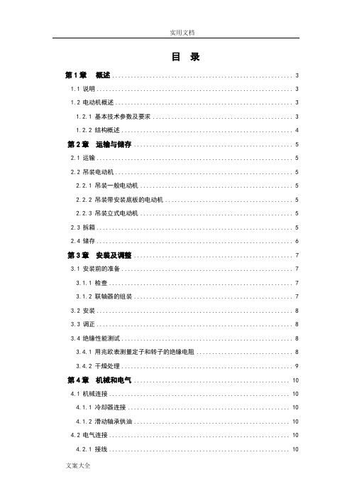
目录第1章概述 (3)1.1说明 (3)1.2电动机概述 (3)1.2.1 基本技术参数及要求 (3)1.2.2 结构概述 (4)第2章运输与储存 (5)2.1运输 (5)2.2吊装电动机 (5)2.2.1 吊装一般电动机 (5)2.2.2 吊装带安装底板的电动机 (5)2.2.3 吊装立式电动机 (5)2.3拆箱 (5)2.4储存 (6)第3章安装及调整 (7)3.1安装前的准备 (7)3.1.1 检查 (7)3.1.2 联轴器的组装 (7)3.2安装 (8)3.3调正 (8)3.4绝缘性能测试 (8)3.4.1 用兆欧表测量定子和转子的绝缘电阻 (8)3.4.2 干燥处理 (9)第4章机械和电气 (10)4.1机械连接 (10)4.1.1 冷却器连接 (10)4.1.2 滑动轴承供油 (10)4.2电气连接 (10)4.2.1 接线 (10)4.2.2 电气及附属设备检查 (10)第5章起动及停车 (12)5.1试起动 (12)5.2转动方向 (12)5.3起动与停车 (12)第6章日常维护 (13)6.1润滑 (13)6.1.1 滚动轴承的润滑 (13)6.1.2 滑动轴承的润滑 (13)6.2振动和噪音 (13)6.3湿度 (13)6.4温度 (13)6.5绝缘电阻的最小值 (14)6.6轴承的更换 (14)6.7定期检查 (15)第7章常见故障及原因分析 (16)第1章概述1.1 说明本说明书为我公司电动机的随机文件。
其中介绍了电动机的结构、储运、安装的要求和注意事项,以及使用、维护电动机的要求、方法和注意事项,使用维护人员必须认真阅读此说明书。
认真审阅电动机上的铭牌、标牌、警示牌等。
使用单位应对操作人员进行专业培训后,方能上岗作业。
只有严格按照本使用说明书、铭牌、标牌、接线牌和警示牌进行安装、使用和维护电动机,我公司才承担相关“三包”责任。
本说明书不可能包括安装、使用和维护方面一切可能发生的问题,如果所发生的问题未包括在本使用说明书和其他随机资料中,用户自己又难以解决,请与本公司联系。
- 1、下载文档前请自行甄别文档内容的完整性,平台不提供额外的编辑、内容补充、找答案等附加服务。
- 2、"仅部分预览"的文档,不可在线预览部分如存在完整性等问题,可反馈申请退款(可完整预览的文档不适用该条件!)。
- 3、如文档侵犯您的权益,请联系客服反馈,我们会尽快为您处理(人工客服工作时间:9:00-18:30)。
.CJ系列电动机操动机构安装使用说明书0SR.412.071.154877江苏省如高高压电器有限公司2014年10月.目录1 概述………………………………………………………………………………………………1.1 产品型号和名称…………………………………………………………………………………1.2产品用途和适用范围……………………………………………………………………………1.3本设备制造执行的标准…………………………………………………………………………1.4 使用环境条件……………………………………………………………………………………2 主要规格及技术参数……………………………………………………………………………3 产品结构与工作原理……………………………………………………………………………3.1 产品结构…………………………………………………………………………………………3.2 工作原理…………………………………………………………………………………………4 安装和调试………………………………………………………………………………………4.1安装前检查………………………………………………………………………………………4.2 安装步骤…………………………………………………………………………………………4.3 产品调试…………………………………………………………………………………………4.4 安装注意事项……………………………………………………………………………………5 操作与运行………………………………………………………………………………………5.1 电动分合闸及停止操作…………………………………………………………………………5.2 现场人力操作分合闸……………………………………………………………………………6 保养和维护………………………………………………………………………………………6.1常规检查和维护…………………………………………………………………………………6.2检查注意事项……………………………………………………………………………………7 验收和贮存………………………………………………………………………………………7.1 验收项目…………………………………………………………………………………………7.2 贮存………………………………………………………………………………………………8 随机文件及随机附件、备件……………………………………………………………………8.1 随机文件…………………………………………………………………………………………8.2 产品成套供应……………………………………………………………………………………8.3 附图………………………………………………………………………………………………9 定货须知…………………………………………………………………………………………10 其他………………………………………………………………………………………………11 常用各种规格钢制普通螺纹连接螺纹的力矩值…………………………………………CJ系列电动机操动机构安装使用说明书1概述1.1 产品型号和名称a) 型号:CJ2、CJ5 、CJ6、CJ9;b) 名称:电动机操动机构。
1.2 产品用途与适用范围CJ系列电动机操动机构(简称操动机构),属户外产品,供操作高压隔离开关之用,可进行远方控制,也可就地用电动控制或用摇把进行人力操作。
1.3 本设备制造执行的标准a) IEC62271-102 高压交流隔离开关和接地开关;b) IEC62271-1 高压开关设备和控制设备标准的共用技术要求;c) IEC 60694 高压开关设备和控制设备标准的共用技术要求。
1.4 使用环境条件a)环境温度:-50℃~+55℃;b)海拔不超过2000m;c)风速不超过34m/s;d)覆冰厚度: 不超过10mm;e)地震烈度: 不超过9度;f)无频繁剧烈振动,无易燃易爆和化学腐蚀物质;g)阳光辐射强度1000W/m2(晴天中午) ;h)不适用于具有大量导电气体、尘埃或足以降低其电气性能及有爆炸危险的场所;i)电源电压变化范围:额定电压的85%~110%。
2 主要规格及技术参数主要技术参数见表1。
表1主要技术参数表1(续)3 产品结构与工作原理3.1产品结构3.1.1 CJ系列机构箱内设有远、近控开关,可实现就地电动分、合闸操作和远方遥控操作;并可用摇把进行人力分、合闸操作,通过摇把的插入与拔出,自动的实现手动与电动相互闭锁。
3.1.2 CJ系列机构采用了先进、可靠、免维护的电动机保护器,该保护器是根据隔离开关电动机构的运行特点设计的,无需外电源,对电动机运行中的对称性故障(如过载、堵转等)及非对称性故障(如断相、电流不平衡)有可靠保护功能。
而且当电机电源断开后,其过流保护装置检测到电流为零后,会在3s左右断开控制回路电源。
3.1.3 CJ系列机构内正常装有8常开、8常闭的辅助开关,由转轴带动辅助开关切换,在隔离开关处于合闸或分闸位置时,发出相应的信号。
3.1.4 CJ系列机构箱采用三面开门结构,极其便于安装维护。
前门可自由打开,侧门通过螺栓紧固,松开螺栓即可卸下。
3.2工作原理3.2.1 CJ系列机构采用电动机驱动蜗轮蜗杆减速装置,带动输出轴工作,输出轴采用垂直安装,具有噪音小的特点。
3.2.2 CJ系列机构中采用电气分、合闸终点限位开关与机械限位装置相配合的方式,使机构主轴限制在准确的位置。
4 安装和调试4.1 安装前检查安装前应检查操动机构有无损坏、转动是否灵活、紧固件是否松动、各电气元件是否完好,确认无损后方可进行安装。
4.2 安装步骤4.3产品调试按图1将机构固定在便于操作且垂直地面的支架上,支架在承受2000N·m弯矩作用时,应不能产生变形及明显晃动,此时调整固定基座的4个M16的螺栓(用户自备)使机构的转轴与隔离开关在同一垂直线上,将机构箱内配供的接头套在机构输出轴上使机构和开关同处在合闸位置,再用钢管将隔离开关和机构上的转轴连接起来。
并手动操作数次,确认准确无误后,按图3进行控制回路接线,同时接上地线,最后用电动形式操作数次,正确无误后即可投入运行。
在额定操作电压85%~110%的范围内,应能保证隔离开关可靠地分闸或合闸。
4.4 安装注意事项注意:1).转换开关QC所处位置;2).在通电操作前,使机构处于分合闸中间位置,然后接上电源,按合闸或分闸按钮。
3).观察交流电动机构主轴转动方向是否符合要求。
若相反,立即切断电源,改换电源线的相序。
4).操动机构的分合闸位置不能以辅助开关切换位置确定,必须以机构的机械定位位置确定。
5).由于电动机保护器的输出接口采用无触点的固态式电子开关,故检验开关的通断特性不能简单的用万用表电阻档来测量。
检测其它电路时可以将该接点1、2短接。
6).装配图1所示夹件时,螺栓需交叉、对称、逐步、均匀拧紧,最后将止紧螺栓按照附表1的参考力矩拧紧。
7). 加热:箱内温度小于或等于5℃或者相对湿度大于或等于85%时。
8). 停止加热:箱内温度大于或等于13℃或者相对湿度小于或等于75%时。
9).当箱内温度低于零下9℃时,温湿度控制器将显示CC,此时不属异常。
5 操作与运行5.1 电动分合闸及停止操作5.1.1现场就地操作电动机操动机构时,转换开关(QC)打在近控位置(其原理图参见附图3),进行电动分闸、电动合闸、电动停止操作。
5.1.2电动分闸:按下分闸按钮(SB3),分闸接触器(KM2)线圈接通,接触器常开触头闭合并自锁,使电动机启动,电动机驱动蜗轮蜗杆减速装置,主轴逆时针方向转动,带动与主轴相连的隔离开关分闸。
当主轴接近分闸终点位置时,装在主轴上定位件使终点限位开关(SL2)分开,切断分闸接触器的控制线圈电源,接触器常开触头打开,切断电动机电源,机械限位装置使机构限制在分闸位置。
5.1.3电动合闸:按下合闸按钮(SB1),合闸接触器(KM1)线圈接通,接触器常开触头闭合并自锁,使电动机启动,电动机驱动蜗轮蜗杆减速装置,主轴顺时针方向转动,带动与主轴相连的隔离开关合闸。
当主轴接近合闸终点位置时,装在主轴上定位件使终点限位开关(SL1)分开,切断合闸接触器的控制线圈电源,接触器常开触头打开,切断电动机电源,机械限位装置使机构限制在合闸位置。
5.1.4电动停止:在分、合过程中,需要中途停止时,可按下停止按钮(SB2),切断控制电源。
5.2 现场人力操作分、合闸用摇把直接操作蜗杆轴,进行分、合闸操作。
摇把插入电动机构蜗杆时,摇把使得微动开关SL3打开,控制回路失电,此时能手动操作,不能电动;将摇把拔出时,SL3合上,控制回路得电,即可进行电动操作。
从而实现手动、电动相互闭锁。
6保养、维护6.1 常规检查和维护产品投入运行后,每年定期检查下列部分是否正常。
常规的检查和维护必须遵照预防性维护见表2,常见的故障判断及处理见表3用摇把操动机构运转,检查各转动部分是否灵活,辅助开关是否能正常切换。
所有紧固零件应无松动现象。
减速箱、限位块、定位件等零部件应无损坏。
检查与调整完毕后,在所有摩擦表面涂上润滑脂。
6.2 检查注意事项表2 预防性维护表7 验收和贮存7.1 验收项目用户收到产品后应在半月内按验收项目进行验收,若发现问题须立即告知我公司,以便共同协商处理。
检查包装箱有无破损,检查产品合格证,安装使用说明书,装箱单等文件是否齐全。
7.2 贮存如果发运到现场后没有立即安装,各包装组件最好在户内存储。
若条件不许可,也可以在户外放置,但各组件应置于通风处,为避免地面潮湿,木箱应置于厚木板(木板厚度≥50mm)上并用防雨帆布覆盖,绑好。
长期存放时,在天气晴好时应撤去帆布干燥。
户外最长储存期不宜超过半年。
存储期间避免受潮和腐蚀,超过半年需开启机构箱的加热器驱潮。
8 随机文件及随机附件、备件8.1 随机文件a)安装使用说明书;b)产品合格证;c)装箱单。
8.2 产品成套供应a) 电动机操动机构 1台;b) 手柄 5RG.253.886.102 1个;c) 夹件 1个(具体配置如下表4所示)。
8.3 附图图1:电动操动机构与隔离开关安装示意图 图2:电动操动机构外形尺寸图图3:a 电动机操动机构接线原理图(电机电压AC380V ,控制电压AC220V/AC380V)b 电动机操动机构接线原理图(电机电压AC380V ,控制电压DC110V/DC220V) c 电动机操动机构接线原理图(电机电压DC220/110V,控制电压DC220/110V) 9 订货须知订货时应说明:机构型号、电机电压、控制电压、机构输出轴转角、辅助开关节点数。
10 其它产品出厂18个月内,确因制造质量问题发生损坏或不能正常工作时,本公司负责修理或更换零件。