EasyPactD3N系列电动机起动与保护
电动机多功能节电保护器原理

电动机多功能节电保护器原理电动机知识平常电动机在轻载或空载状态下的工作效率是非常低的。
电动机连续工作必须消耗一定的能量以提供磁场。
当供给电动机的端电压恒定时,产生的磁通也保持恒定。
在额定转速下,磁场消耗的能量保持恒定,与负载所需的转矩无关,支持负载转矩的能量大小取决于电磁转矩的大小。
当负载转矩增加,转子的转速会稍微下降(转差率增大),使得感应的转子电流上升以增加电磁转矩。
相反,如果需要的负载转矩减少,转差率减少,转子电流下降,定子电流也相应下降。
但在端电压恒定的情况下,定子提供磁场的电流在任何负载转矩条件下将保持恒定。
结果是感应电机的效率随负载的减少而降低。
通常电机始终在额定条件下运转的情况很少。
我们挑选的电机其标称均低于驱动功率时最小市场需求。
当输出额定电压时即使满负荷运转也存有节电空间。
此时,驱动的功率通常也不是恒定维持不变的。
而挑选的电机大小必须满足用户其最小负荷时的市场需求,尽管最小负荷只是间断发生,其他时间负荷必须小得多。
由于电机产生的转矩与供电电压的平方成正比,减少端电压将增加转矩。
减少电压实际上就是减少了电机的额定输出功率。
也意味著所须要磁场能量的增加。
利用这一原理。
鑫科的电动机多功能节电保护器可以在从短程至多数功率情况下维持恒定的电机效率。
它使用智能化的微处理器掌控,无须人工调节。
在重功率的情况下电机的电压自动降到最高市场需求,而输出功率维持恒定,因此减少了不必的损耗。
如果功率减少,电压将自动下降以避免电机减速。
通过闭环反馈系统控制,其感应电路比较通过电机的电压和电流波形。
由于是电感电路,电压和电流波形存在时间差,功率越轻,电流波形的落后越大。
电流相对于电压的落后关系同的负荷条件下,和电动机多功能节电保护器已连续监测电机电压电流之间的相位角,依据负荷的变化发生改变相位角。
它通过采用晶闸管半导体控制器元件去焊接电压而展开掌控。
晶闸管容许电源电压正半周和负半周的一部分供给电机。
〃节能环保给电机行业增添的机遇〃交流电机变频调速器的应用领域分析〃变频器基频设置参数的概念〃煤矿井下刮板运输机电机损坏原因分折及〃异步电动机绕组损坏的原因及处理方法〃zqdr-410型牵引电动机的故障分析及对策〃光电开关原理及应用直流无刷电动机工作〃电气检修综合专业人员技能和工作职责〃电机型号及参数〃节能环保造就崭新商机电气巨头掘金高效电机〃jy系列单项电容再生制动异步电动机结构特点〃西门子变频器工作原理/上海代理西门子〃变频器在电机采用中的节能环保原理〃基于不同电动机负载下变频器容量的选择〃变频器调整必须知道的几个参数〃软起动器在煤气洗涤泵站的应用〃电机基本知识和怎样恰当挑选电动机〃变频器的应用及运行过程中的问题处理〃变频器过电压产生的原因(二)〃西门子变频器产品及选型〃电动机软起动器在水泥企业的采用〃acc800变频器的应用领域〃变频器的容量计算与选择〃三相电机七种调速方式〃变频器选型、加装、测量与接线规范(一〃恒功率变频器存有什么促进作用?〃叶轮式增氧机的安全使用和检修保养〃变频器转差频率控制方式〃变频器频率取值方式及原理科学知识〃大惯性负载起动时变频器容量的计算匿名随着起重机的不断发展,传统控制技术难以满足用户起重机越来越低的变频和掌控建议。
傲马系列电动机起动控制设备
快速安装方案
使用标准控制单元的 电动机起动 - 控制器
使用高级控制单元的 电动机起动 - 控制器
电磁断路器或熔断器
使用多功能控制单元的 电动机起动 - 控制器
电磁断路器或熔断器
接触器
接触器
使用高级控制单元的 电动机起动 - 控制器
使用多功能控制单元的 电动机起动 - 控制器
(1) 并行通信模块
Schneider Electric
基本起动 - 控制器
包括一个动力底座和一个控制单元。 动力底座 1 它与控制电压和电动机功率无关。 具有断路器功能, 400 V 下分断能力达 50 kA,全配合标准,并具有动力切换功能 ( 接触器功能 ) b 提供 2 种额定值:0…12 A 和 0…32 A。 b 无可逆 (LUB) 和可逆 (LU2B)。 控制单元 2 控制单元需要根据控制电压、电动机功率和所需保护的类型进行选择。 b 标准控制单元 (LUCA):满足电动机起动器的基本保护要求:热过载和短路 ( 详细内容见 19 页 )。 b 高级控制单元 (LUCB、LUCC 或 LUCD):( 在标准控制单元基础上 ) 增加了报警、故障区分等 高级功能 ( 详细内容见 19 页 )。 b 多功能控制单元 (LUCM):适用于最复杂的控制和保护要求 ( 详细内容见 20 页 )。 这些控制单元无需重新连线且无需工具即可互换,具有宽幅调整范围 ( 范围为 4 倍 ) 和低热耗散。
TeSys U !
®
-
!"# !
!
目录
0
TeSys U — “傲马”系列
页码
TeSys U 型电动机起动 - 控制器
b 选型指南 . . . . . . . . . . . . . . . . . . . . . . . . . . . . . . . . . . . . . . . . . . . . . . . . . . . . . . . 2 b 介绍 . . . . . . . . . . . . . . . . . . . . . . . . . . . . . . . . . . . . . . . . . . . . . . . . . . . . . . . . . . . 4 b 应用举例 . . . . . . . . . . . . . . . . . . . . . . . . . . . . . . . . . . . . . . . . . . . . . . . . . . . . . . . 8 b 动力底座 . . . . . . . . . . . . . . . . . . . . . . . . . . . . . . . . . . . . . . . . . . . . . . . . . . . . . . 14 v 不可逆动力底座 . . . . . . . . . . . . . . . . . . . . . . . . . . . . . . . . . . . . . . . . . . . . . . . 14 v 可逆动力底座 . . . . . . . . . . . . . . . . . . . . . . . . . . . . . . . . . . . . . . . . . . . . . . . . . 15 b 附加触点和辅助触点模块 . . . . . . . . . . . . . . . . . . . . . . . . . . . . . . . . . . . . . . . . . . 16 b 附件 . . . . . . . . . . . . . . . . . . . . . . . . . . . . . . . . . . . . . . . . . . . . . . . . . . . . . . . . . . 17 b 控制单元 . . . . . . . . . . . . . . . . . . . . . . . . . . . . . . . . . . . . . . . . . . . . . . . . . . . . . . 18 b 功能模块 . . . . . . . . . . . . . . . . . . . . . . . . . . . . . . . . . . . . . . . . . . . . . . . . . . . . . . 21 b 15-315 kW 的电动机控制器 . . . . . . . . . . . . . . . . . . . . . . . . . . . . . . . . . . . . . . . . 22 b 并行接口和线圈预接线模块 . . . . . . . . . . . . . . . . . . . . . . . . . . . . . . . . . . . . . . . . 24 b Advantys STB 分布式 I/O 预接线模块 . . . . . . . . . . . . . . . . . . . . . . . . . . . . . . . . 26 b 通信模块和线圈预接线模块 . . . . . . . . . . . . . . . . . . . . . . . . . . . . . . . . . . . . . . . . 28 v AS-i 通信模块 . . . . . . . . . . . . . . . . . . . . . . . . . . . . . . . . . . . . . . . . . . . . . . . . . 28 v Modbus 通信模块 . . . . . . . . . . . . . . . . . . . . . . . . . . . . . . . . . . . . . . . . . . . . . . 30 b 通信网关 . . . . . . . . . . . . . . . . . . . . . . . . . . . . . . . . . . . . . . . . . . . . . . . . . . . . . . 32 b 15 kW 以下产品特性 . . . . . . . . . . . . . . . . . . . . . . . . . . . . . . . . . . . . . . . . . . . . . 34 b 15-315 kW 产品特性 . . . . . . . . . . . . . . . . . . . . . . . . . . . . . . . . . . . . . . . . . . . . . 40 b 脱扣曲线和限制曲线 . . . . . . . . . . . . . . . . . . . . . . . . . . . . . . . . . . . . . . . . . . . . . 42 b 根据电气寿命选型 . . . . . . . . . . . . . . . . . . . . . . . . . . . . . . . . . . . . . . . . . . . . . . . 46 b 尺寸 . . . . . . . . . . . . . . . . . . . . . . . . . . . . . . . . . . . . . . . . . . . . . . . . . . . . . . . . . . 48 b 电路图 . . . . . . . . . . . . . . . . . . . . . . . . . . . . . . . . . . . . . . . . . . . . . . . . . . . . . . . . 50 b 建议应用方案 . . . . . . . . . . . . . . . . . . . . . . . . . . . . . . . . . . . . . . . . . . . . . . . . . . . 57
电机电路中的变频开关、软启动器和其他电源电子设备的保护说明书

Variable frequency drives, soft starters, and other power electronic devices are becoming increasingly more common in motor circuits. These power electronic devices are much more sensitive to the damaging effects of short-circuit currents and therefore require a level of protection that may not be provided by circuit breakers or conventional fuses. In the past, manufacturers of these devices provided internal protection in the form of high speed fuses, which are much more current-limiting than conventional branch circuit fuses. However, as drives and soft-starters have grown smaller and smaller, the internal fuses have been omitted by starter manufacturers in favor of short-circuit testing to UL standards with external protection.Now, in many cases, drives are shipped without fuses, and it is the responsibility of the installer or owner to provide this protection. During the design and installation stages, it is important to check the data sheets, label, or manual of the power electronic device to understand the short-circuit protection options. With the proper fuse selection, a safer installation may result, with better power electronic device protection. This can result in more productive operation and higher short-circuit current ratings.Short Circuit TestingUL508C, the standard to which drives and soft starters are listed, provides at least two levels of short-circuit protection. The Standard Fault Current test is mandatory to be listed, and there is an optional High Fault Current test which can be performed during the listing of the device.UL also provides an “Outline of Investigation”, UL508E, which can be used to verify Type 2 (no damage) protection when protected by a specific current-liming overcurrent protective device.1. The Standard Fault Current tests evaluate the drives at rather low levels of fault current, and significant damage to the drive is permitted – i.e. the drive does not have to be operational after the testing. Examples of the level of fault currents are 5000 amps for 1.5 to 50Hp drives and 10,000 amps for 51 to 200Hp drives.The drive must be marked with the maximum short-circuit current rating (at which it was tested). It does not have to be marked with the type overcurrent protective device if it has followed certain procedures. However, the manufacturer can list the drive with fuse protection only and then the label will be marked to identify that branch-circuit protection shall be provided by fuses only (either high speed or branch circuit types).2. The High Fault Current tests can be at any level of short-circuit current above the standard fault current tests. Significant damage to the drive is permitted – i.e. the drive does not have to be operational after the testing. The drive must be marked with the short-circuit current rating at which it was tested. In addition it must be marked with the type overcurrent protective device(s) that were used for the test. If current-limiting branch circuit fuses (such as Class J, T, CC, etc.) are used, then the tests are conducted with special umbrella fuses. Umbrella fuses have energy let-through levels greater than the UL limits for various classes and amp rated fuses. These umbrella fuses have energy let-through levels that are greater than commercially available fuses.A drive can be listed and marked for either fuses or circuit breakers or both. Typically the drives are marked for protection only by fuses since current-limitation is necessary to meet the requirements set forth in the product standard. If the unit is marked for fuse protection only, then only fuses can be used for protection of that drive unit and the proper type and size must be used. Some drives will be marked for protection by a specific amp and class fuse (for branch circuit fuses).3. Type 2 (no damage)is the best level of protection. With this protection, the drive cannot be damaged, and the unit is tested and marked with a high short-circuit current rating. It must be able to be put into service after the fault has been repaired and the fuses replaced.A clear understanding of semiconductor device types is needed when considering Type 2 coordination with variable speed drives. Only silicon controlled rectifier (SCR), gate turn-off thyristor (GTO) and diode based devices can achieve Type 2 protection, and it is only possible with properly selected high speed fuses. Thyristor type devices can effectively share energy equally across the PN junction. They have short-circuit energy withstand levels that are lower than conventional branch circuit fuse let-throughs, however, Type 2 protection can be achieved with properly selected high-speed fuses. Equipment that use insulated gate bipolar transistors (IGBT) high frequency devices cannot presently achieve Type 2 protection levels. IGBTs do not have enough surface area contact with the actual junction to help share energy evenly. IGBTs share energy very well during long duration pulses, but during short duration, high amplitude faults most of the energy is being carried by an individual bonding wire or contact. Current fuse technology cannot effectively protect the bonding wires of IGBT based equipment from overcurrent conditions, and therefore Type 2 no damage protection is not possible. However, current high speed fuse technology can protect IGBTs from case rupture under short-circuit conditions.Protecting Drives and Soft StartersThere are two important considerations when selecting protective devices for drives and soft starters:1. The device must be able to withstand the starting current and duty cycle of themotor circuit without melting.2. The device must be able to clear a fault quickly enough to minimize damage tothe drive or soft starter.The melting time current characteristic curve can be used to verify a fuse’s ability to withstand starting currents and duty cycle, while clearing I2t at the available fault current can be used to verify the various levels of protection described earlier. For more information on proper sizing of high speed fuses, please see the High Speed Application Guide, available on.There are two types of faults that can occur with drives and soft starters –internal faults and external faults. Internal faults are caused by failures of components within the drive or soft starter, such as failure of the switching components (SCRs, thyristors, IGBTs, etc.) External faults occur elsewhere in the circuit, such as a motor winding faulting to the grounded case.Most soft starters utilize either silicon-controlled rectifiers (SCRs) or gate turn-off thyristors (GTOs) for power conversion. These devices depend on high speed fuses for protection from both internal and external faults. If high speed fuses are properly selected, Type 2 protection may be achieved.Modern adjustable speed drives often utilize insulated gate bipolar transistors (IGBTs) as the main switching components. IGBTs have drastically lower energy withstands than SCRs and GTOs, which makes protection of these components very difficult. For external faults, drives using IGBTs incorporate electronic protection that shut off the switching components when fault currents are detected. However, over time, transient voltage surges can lead to the electronics’inability to shut off the IGBT switching. This can lead to internal faults as the IGBTs fail and rupture. The violent rupture of IGBTs can cause additional faults to adjacent components as a result of the expelling of gases and shrapnel. High speed fuses may not be able to prevent the IGBT from failing, but properly selected high speed fuses can prevent the violent rupture of IGBT devices and the resultant additional faults and safety hazard. Large adjustable speed drives often include internal high speed fusing in order to protect against rupturing of components. However, small drives (belowMotor Circuits With Power Electronic DevicesPower Electronic Device Circuit Protection181200Hp) often do not include internal fusing, so the user must supply protection. It is important to note that Type 2 or “no damage” protection of devices utilizing IGBTs is not possible with current fuse technology. However, with properly sized and applied high speed fuses, repair, replacement and lost productivity costs will be minimized.Fuses for Specific DrivesSelection tables for various manufacturers’drives with Cooper Bussmann fuse recommendations by specific drive model / part # are available on.Complying with the NEC®Traditional high speed fuses come in many different shapes and sizes. They can be recognized to UL and CSA standard 248-13. This standard does not contain requirements for overload performance or dimensions, therefore, these fuses are not considered branch circuit protection per the NEC®. However, NEC®article 430, which covers motor circuits, does allow high speed fuses to be used in lieu of branch circuit protection when certain conditions are met.New: Cooper BussmannSeries DFJ (Class J) Drive FuseThe Cooper Bussmann Drive Fuse (Series DFJ) provides the performance of a high speed fuse for protection of semiconductor devices and meets UL listing requirements for Class J fuses. Unlike traditional high speed fuses, the Cooper Bussmann DFJ Drive Fuse is suitable for branch circuit protection (per the NEC®), and fits in standard Class J fuse clips, holders and disconnects.Motor Circuits With Power Electronic DevicesPower Electronic Device Circuit Protection The use of high speed fuses for protection of power electronic devices in lieuof normal branch circuit overcurrent protective devices is allowed per NEC®430.52(C)(5), which states that “suitable fuses shall be permitted in lieu of devices listed in Table 430.52 for power electronic devices in a solid statemotor controller system, provided that the marking for replacement fuses is provided adjacent to the fuses.” Please note that this only allows the use ofhigh speed fuses in lieu of branch circuit protection.Per NEC®430.124(A), if the adjustable speed drive unit is marked that it includes overload protection, additional overload protection is not required.NEC® 430.128 states that the disconnecting means for an adjustable speed drive system shall have a rating not less than 115% of the rated input currenton the drive unit. This means that the disconnect required in front of eachdrive unit must be sized in accordance with the drive unit rated input current,not the motor current. When connecting conductors between the disconnecting means and the drive, NEC®430.122(A) states that “Circuit conductors supplying power conversion equipment included as part of an adjustable speed drive system shall have an ampacity not less than 125% ofthe rated input to the power conversion equip-ment.” This means that the conductors shall be sized to the rated current on the conversion unit nameplate and not the motor rating.Figure 1 - The above comparison of time-current characteristics shows the superior performance of the CooperBussmann DFJ Drive Fuse at three critical performancepoints.Figure 1 represents the typical starting parameters of an AC drive, as well as the melting characteristics of a traditional, non-time delay, Class J fuse and the new DFJ Drive Fuse from Cooper Bussmann. There are three critical performance points that are shown:A: Continuous Region (Amp Rating)– The continuous current-carrying capacity of the DFJ Drive Fuse is identical to the tradition Class J fuse. This is key to meeting UL branch circuit opening time requirements.B: Overload Region– Traditional, non-time delay Class J fuses have far less overload withstand than the new DFJ Drive Fuse from Cooper Bussmann. Thisextended withstand allows for more reliable protection without nuisance openings. C: Short-Circuit Region– The DFJ Drive Fuse has far lower required melting current and clearing I2t than the traditional Class J fuse, allowing for greater cur-rent limitation and lower energy let-through.182183Figure 2 – The graph shown above is a representation of the ener-gy let-through by a circuit breaker, a standard, non-time delay Class J fuse, and the new Cooper Bussmann DFJ Drive Fuse during the same magnitude fault.Under fault conditions, the DFJ Drive Fuses clear the fault much faster, and are much more current-limiting, than circuit breakers and standard, non-time delay Class J fuses. The DFJ Drive Fuse has high speed fuse performance under fault conditions, which means high speed fuse protection for power electronic devices.Motor Circuits With Power Electronic DevicesPower Electronic Device Circuit Protection。
施耐德断路器型号系列

施耐德断路器1、断路器概述是一种过电流保护装置,指能够关合、承载和开断正常回路条件下的电流,并能关合、在规定的时间内承载和开断异常回路条件(包括短路条件)下的电流的开关装置。
2、断路器分类微型断路器塑壳断路器框架断路器三种断路器在额定电流和分断能力上并无非常严格的划分,一些小型断路器在额定电流和分断能力上也可以达到塑壳断路器的低端标准,而一些塑壳断路器也可以到框架断路器的低端标准。
3、断路器简介1. 微型断路器微型断路器的作用:短路保护、过载保护、隔离。
主要的:Acti9(取代M9 ):IC65 、C65 小型直流断路器、C60、IDPN 、C120、NG125 、DPN 、INT125 系列隔离开关。
IC65 为C65 的升级产品,IDPN 为DPN 的升级替代产品。
E9(Easy9):EA9AN 、EA9AH 、EA9A45 、EA9A65 、EA9A47 、EA9A67 、EA9D 隔离开关(关合,隔离)、Osmart 系列:C32N 、C65H、K 系列专为OEM 市场推出的,其价格与性能估计与EASY9 系列差不多,比ic65 总体要低。
例如分断能力只有6KA ,没有10KA 及15KA 的产品;没有1P+N 的产品等等选型的参数:分断能力、脱扣曲线、额定电流、极数。
分断能力:是指断路器安全切断故障电流的能力分断能力:Q 36-50kA: 标准应用:民用住宅、零售商店、医院、学校、公共建筑、工业厂房。
Q 70-100kA: 高性能要求的应用:工业生产线、关键电力设备。
Q 150kA:特殊应用:船舶、重工业。
脱扣曲线B 型曲线:保护短路电流较小的负载(如电源、长电览等),瞬时脱扣范围(3~5) InC 型曲线:保护常规负载和配电线缆,瞬时脱扣范围(5~10) InD 型曲线:保护起动电流大的冲击性负荷(如电动机,变压器等),瞬时脱扣范围(10~14) InViSiSafe 看得见的安全升级款 5代(Acti9系列)在一般环境和条件下r ViSiSafe 都 可确保下级电路的可靠安全。
三相异步电动机启动方法

三相异步电机的启动方法三相异步电动机的起动方法主要有直接起动、传统减压启动和软启动三种启动方法。
下面就分别做详细介绍。
2.2.1 直接起动直接起动,也叫全压起动。
起动时通过一些直接起动设备,将全部电源电压(即全压)直接加到异步电动机的定子绕组,使电动机在额定电压下进行起动。
一般情况下,直接起动时起动电流为额定电流的3~8倍,起动转矩为额定转矩的1~2倍。
根据对国产电动机实际测量,某些笼型异步电动机起动电流甚至可以达到8~12倍。
直接起动的起动线路是最简单的,如图2-2所示。
然而这种起动方法有诸多不足。
对于需要频繁起动的电动机,过大的起动电流会造成电动机的发热,缩短电动机的使用寿命;同时电动机绕组在电动力的作用下,会发生变形,可能引起短路进而烧毁电动机;另外过大的起动电流,会使线路电压降增大,造成电网电压的显著下降,从而影响同一电网的其他设备的正常工作,有时甚至使它们停下来或无法带负载起动。
这是因为Ts 及Tm 均与电网电压的平方成正比,电网电压的显著下降,可使Ts 及Tm 均下降到低于Tz 。
一般情况下,异步电动机的功率小于7.5kW 时允许直接起动。
如果功率大于7.5kW ,而电源总容量较大,能符合下式要求的话,电动机也可允许直接起动。
()()111134st N kv A I K I kw ⎡⎤⋅=≤+⎢⎥⎣⎦电源总容量起动电动总功率如果不能满足上式的要求,则必须采用减压启动的方法,通过减压,把启动电流Ist 限制到允许的数值。
FU图2-2 直接启动原理图2.2.2 传统减压起动减压起动是在起动时先降低定子绕组上的电压,待起动后,再把电压恢复到额定值。
减压起动虽然可以减小起动电流,但是同时起动转矩也会减小。
因此,减压起动方法一般只适用于轻载或空载情况。
传统减压起动的具体方法很多,这里介绍以下三种减压起动的方法:(1)定子串接电阻或电抗起动定子绕组串电阻或电抗相当于降低定子绕组的外加电压。
由三相异步电动机的等效电路可知:起动电流正比于定子绕组的电压,因而定子绕组串电阻或电抗可以达到减小起动电流的目的。
三相异步电动机有几种启动方式
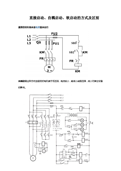
直接启动、自耦启动、软启动的方式及区别直接启动就是接通电源直接启动自耦起动这种方式在起动时电机接于低压侧,电流较小,能减小线路压降,减小对其它设备的影响。
软起动是一种集电机软起动、软停车、轻载节能和多种保护功能于一体的新颖电机控制装置,它的主要构成是串接于电源与被控电机之间的三相反并联闸管及其电子控制电路。
运用不同的方法,控制三相反并联闸管的导通角,使被控电机的输入电压按不同的要求而变化,就可实现不同的功能。
直接启动就是接通电源设备直接启动自耦起动是一种常见的降压起动方式,但存在明显缺点,即起动过程中出现二次冲击电流。
运用串接于电源与被控电机之间的软起动器,控制其内部晶闸管的导通角,使电机输入电压从零以预设函数关系逐渐上升,直至起动结束,赋予电机全电压,即为软起动,在软起动过程中,电机起动转矩逐渐增加,转速也逐渐增加。
软起动一般有下面几种起动方式。
a斜坡升压软起动。
这种起动方式最简单,不具备电流闭环控制,仅调整晶闸管导通角,使之与时间成一定函数关系增加。
其缺点是,由于不限流,在电机起动过程中,有时要产生较大的冲击电流使晶闸管损坏,对电网影响较大,实际很少应用。
b斜坡恒流软起动。
这种起动方式是在电动机起动的初始阶段起动电流逐渐增加,当电流达到预先所设定的值后保持恒定(t1至t2阶段),直至起动完毕。
起动过程中,电流上升变化的速率是可以根据电动机负载调整设定。
电流上升速率大,则起动转矩大,起动时间短。
该起动方式是应用最多的起动方式,尤其适用于风机、泵类负载的起动。
c阶跃起动。
开机,即以最短时间,使起动电流迅速达到设定值,即为阶跃起动。
通过调节起动电流设定值,可以达到快速起动效果。
d脉冲冲击起动。
在起动开始阶段,让晶闸管在级短时间内,以较大电流导通一段时间后回落,再按原设定值线性上升,连入恒流起动。
该起动方法,在一般负载中较少应用,适用于重载并需克服较大静摩擦的起动场合。
再说一下软起动与传统减压起动方式的不同之处:笼型电机传统的减压起动方式有星三角起动、自耦减压起动、电抗器起动等。
三相异步电动机的启动方法 三相异步电动机常见问题解决方法
三相异步电动机的启动方法三相异步电动机常见问题解决方法(1)直接启动定义:利用闸刀开关、交流、空气自动开关等电器将直接接入启动。
优点:设备简单,操作便利,启动快速。
缺点:启动电流大。
一般地,以下情形可以接受(1)直接启动定义:利用闸刀开关、交流、空气自动开关等电器将直接接入启动。
优点:设备简单,操作便利,启动快速。
缺点:启动电流大。
一般地,以下情形可以接受直接启动方式:①容量在10kW及以下的允许直接启动;②启动时,电动机的启动电流在供电线路上引起的电压降不超过正常电压的,假如没有独立变压器(与照明共用),则不应超过;③用户有独立的变压器供电时,频繁启动的电动机容量小于变压器容量的时允许直接启动;不频繁启动时电动机容量小于变压器的时允许直接启动。
(2)降压启动当电动机的容量较大,电源容量不能充分直接启动要求时,为了减小,常用此法。
定义:利用启动设备,在启动时降低加在定子绕组上的电压,当电动机的转速接近额定转速时,再全电压(额定电压)运行。
适用于启动时负载转矩不大的情况。
—专业分析仪器服务平台,试验室仪器设备交易网,仪器行业专业网络宣扬媒体。
相关热词:等离子清洗机,反应釜,旋转蒸发仪,高精度温湿度计,露点仪,高效液相色谱仪价格,霉菌试验箱,跌落试验台,离子色谱仪价格,噪声计,高压灭菌器,集菌仪,接地电阻测试仪型号,柱温箱,旋涡混合仪,电热套,场强仪万能材料试验机价格,洗瓶机,匀浆机,耐候试验箱,熔融指数仪,透射电子显微镜。
三相异步电动机常见故障及处理方法一、电动机起动困难,额定负载时,电动机转速低于额定转速较多1、故障原因①电源电压过低;②三角形接法误接为Y;③笼型转子开焊或断裂;④绕线电动机的集电环与电刷接触不良,从而使接触电阻增大损耗增大,输出功率削减;⑤电源缺相;⑥电机过载;⑦绕线电动机转子回路串电阻过大。
2、故障排出①测量电源电压,设法改善;②矫正接法;③检查开焊和断点并修复;④调整电刷压力,用细砂布磨好电刷与集电环的接触面;⑤对于由于熔断器断路显现的断相运行,应先检查出原因,然后更换熔断器熔丝;⑥减载;⑦适当减小转子回路串接的变阻器阻值。
三相异步电动机启动控制原理图
三相异步电动机启动控制原理图1、三相异步电动机的点动控制点动正转控制线路是用按钮、接触器来控制电动机运转的最简单的正转控制线路。
所谓点动控制是指:按下按钮,电动机就得电运转;松开按钮,电动机就失电停转。
典型的三相异步电动机的点动控制电气原理图如图3-1(a)所示。
点动正转控制线路是由转换开关QS、熔断器FU、启动按钮SB、接触器KM及电动机M组成。
其中以转换开关QS作电源隔离开关,熔断器FU作短路保护,按钮SB控制接触器KM的线圈得电、失电,接触器KM的主触头控制电动机M的启动与停止。
点动控制原理:当电动机需要点动时,先合上转换开关QS,此时电动机M尚未接通电源。
按下启动按钮SB,接触器KM的线圈得电,带动接触器KM的三对主触头闭合,电动机M便接通电源启动运转。
当电动机需要停转时,只要松开启动按钮SB,使接触器KM 的线圈失电,带动接触器KM的三对主触头恢复断开,电动机M失电停转。
在生产实际应用中,电动机的点动控制电路使用非常广泛,把启动按钮SB换成压力接点、限位节点、水位接点等,就可以实现各种各样的自动控制电路,控制小型电动机的自动运行。
2.三相异步电动机的自锁控制三相异步电动机的自锁控制线路如图3-2所示,和点动控制的主电路大致相同,但在控制电路中又串接了一个停止按钮SB1,在启动按钮SB2的两端并接了接触器KM的一对常开辅助触头。
接触器自锁正转控制线路不但能使电动机连续运转,而且还有一个重要的特点,就是具有欠压和失压保护作用。
它主要由按钮开关SB(起停电动机使用)、交流接触器KM(用做接通和切断电动机的电源以及失压和欠压保护等)、热继电器(用做电动机的过载保护)等组成。
欠压保护:“欠压”是指线路电压低于电动机应加的额定电压。
“欠压保护”是指当线路电压下降到某一数值时,电动机能自动脱离电源电压停转,避免电动机在欠压下运行的一种保护。
因为当线路电压下降时,电动机的转矩随之减小,电动机的转速也随之降低,从而使电动机的工作电流增大,影响电动机的正常运行,电压下降严重时还会引起“堵转”(即电动机接通电源但不转动)的现象,以致损坏电动机。
施耐德LC1E选型
11 kW 18.5 kW 22 kW 22 kW 30 kW
18.5 kW 30 kW 37 kW 37 kW 37 kW
22 kW 37 kW 45 kW 45 kW 45 kW
125 A
25 kW 45 kW 45 kW 55 kW 45 kW
24...415V,根据线圈电压编号
p
p
p
p
p
p
p
p
p
p
LC1E06 LC1E09 LC1E12 LC1E18 LC1E25 LC1E32 LC1E38 LC1E40 LC1E50 LC1E65
页码
接触器
4
(1):浪涌抑制模块为选配附件,详见P17页。
注:400A至630A上市时间为2013年第二季度。
2
80A
95A
120A
160A
200 kW
250 kW
335 kW
220/250 kW 280/295 kW 375/400 kW
257 kW
355 kW
400 kW
280 kW
335 kW
450 kW
接触器内置1个常开和1个常闭触点
-
17...104 A 17...104 A 51...135
51...198
51...234
51...279
12A
18A
25A
32A
38A
40A
50A
65A
20A
20A
25A
25A
32A
40A
40A
50A
60A
80A
a 690 V
3
3
3
3
3
施耐德EasyPact TVS 系列(电动机起动与保护)选型简易手册
321...513
394...630
(A)
型号
LRE02N
LRE10N
LRE14N
LRE16N
LRE21N
LRE22N
LRE32N
LRE355N
LRE357N
LRE359N
LRE363N
LRE365N
LRE480N
LRE482N
LRE483N
LRE485N
LRE486N
LRE487N
LRE488N
LRE489N
客户关爱中心热线:400 810 1315
施耐德电气中国 Schneider Electric China
北京市朝阳区望京东路6号 施耐德电气大厦 邮编: 100102 电话: (010) 8434 6699 传真: (010) 8450 1130
Байду номын сангаас
代码
厂生产
(更多电流等级见下表)
06
6A
25
25A
50
50A
120 120A
300 300A
09
9A
32
32A
65
65A
160 160A
400 400A
12
12A
38
38A
80
80A
200 200A
500 500A
6A-38A自带1常开或1常闭辅助触点。 40A-160A自带1常开和1常闭辅助触点。 200A-630A不自带辅助触点。
AC** (60 Hz) B6 F6 M6 Q6
AC*** (50/60Hz) E7 F7 M7 Q7
附件
LAENppN • 夹持安装辅助触点模块
- 1、下载文档前请自行甄别文档内容的完整性,平台不提供额外的编辑、内容补充、找答案等附加服务。
- 2、"仅部分预览"的文档,不可在线预览部分如存在完整性等问题,可反馈申请退款(可完整预览的文档不适用该条件!)。
- 3、如文档侵犯您的权益,请联系客服反馈,我们会尽快为您处理(人工客服工作时间:9:00-18:30)。
EasyPact D3N电动机热磁断路器
特性 ............................................................................................. 49 电动机热磁断路器选型 ................................................................. 51 尺寸及安装................................................................................... 55
在施耐德电气,我们称之为:Life Is On
施耐德电气中国
• 中国已经成为集团在全球第二大市场 • 在中国拥有 26000 名员工 • 3 个主要研发中心和 1 个施耐德电气研修学院 • 26 家工厂、8 个物流中心、6 个分公司和 38 个办事处遍布全国
目录
EasyPact D3N系列
EasyPact D3N接触器
EasyPact D3N热过载继电器
特性 ............................................................................................. 40 热过载继电器选型 ........................................................................ 43 尺寸及安装................................................................................... 45
EasyPact D3N电动机起动器
起动器组合用户自行组装 ............................................................. 57
1
选型指南
应用
EasyPact D3N 3极接触器
LC1N06到630
各种类型的控制系统
额定工作电流
Ie max AC-3 (Ue≤440 V) Ie AC-1
额定工作电压
极数
额定工作功率 AC-3 类
220/230 V 380/400 V 415/440 V 500 V 660/690 V
内置辅助触点模块
6A
9A
12A
18A
25A
32A
38A
40A
50A
65A
20A
20A
25A
25A
32A
40A
40A
60A
80A
80A
a 690 V
3
3
3
3
3333源自331.5 kW 2.2 kW 2.2 kW 3 kW 3 kW
2.2 kW 4 kW 4 kW 5.5 kW 5.5 kW
3 kW 5.5 kW 5.5 kW 7.5 kW 7.5 kW
4 kW 7.5 kW 9 kW 10 kW 10 kW
接触器内置1个常开或1个常闭触点
5.5 kW 11 kW 11 kW 15 kW 15 kW
7.5 kW 15 kW 15 kW 18.5 kW 18.5 kW
EasyPact D3N系列
电动机起动与保护
产品目录2018
施耐德电气是全球能效管理和自动化领域的专家,致力于为客户提供安全、可靠、高效、经济以及环保的能源和过程管理。 集团 2016 财年销售额为 247 亿欧元,在全球 100 多个国家拥有 16 万名员工。从简单的开关产品到复杂的运营系统,我 们的技术、软件和服务帮助客户管理和优化运营,通过互联互通的科技助力产业优化,改善城市生态,丰富人们的生活。
9 kW 18.5 kW 18.5 kW 18.5 kW 18.5 kW
11 kW 18.5 kW 22 kW 22 kW 30 kW
EasyPact D3N控制继电器
特性 ............................................................................................. 36 控制继电器选型............................................................................ 38 安装尺寸 ...................................................................................... 39