RMH公司及产品介绍-2015.6.3
RM对比敏感度产品介绍
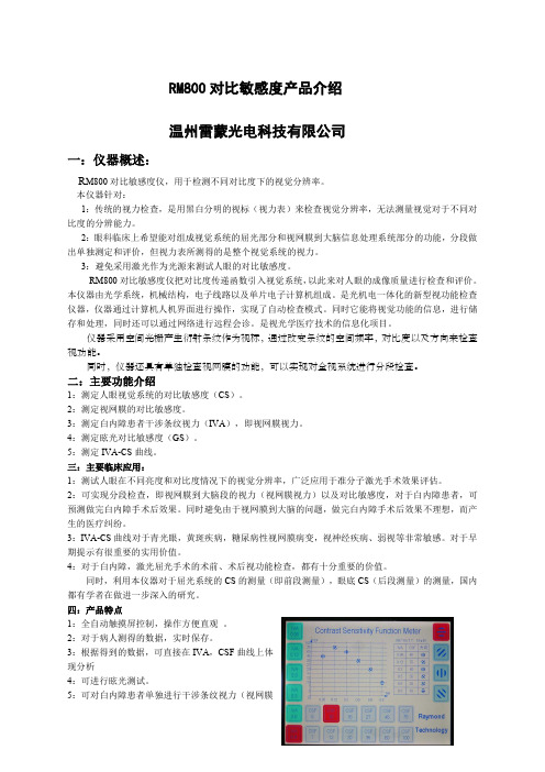
RM800对比敏感度产品介绍温州雷蒙光电科技有限公司一:仪器概述:R M800对比敏感度仪,用于检测不同对比度下的视觉分辨率。
本仪器针对:1:传统的视力检查,是用黑白分明的视标(视力表)来检查视觉分辨率,无法测量视觉对于不同对比度的分辨能力。
2:眼科临床上希望能对组成视觉系统的屈光部分和视网膜到大脑信息处理系统部分的功能,分段做出单独测定和评价,但视力表所测得的是整个视觉系统的视力。
3:避免采用激光作为光源来测试人眼的对比敏感度。
RM800对比敏感度仪把对比度传递函数引入视觉系统,以此来对人眼的成像质量进行检查和评价。
本仪器由光学系统,机械结构,电子线路以及单片电子计算机组成。
是光机电一体化的新型视功能检查仪器,仪器通过计算机人机界面进行操作,实现了自动检查模式。
同时它能将视觉功能的信息,进行储存和处理,同时还可以通过网络进行远程会诊。
是视光学医疗技术的信息化项目。
仪器采用空间光栅产生衍射条纹作为视标,通过改变条纹的空间频率,对比度以及方向来检查视功能。
同时,仪器还具有单独检查视网膜的功能,可以实现对全视系统进行分段检查。
二:主要功能介绍1:测定人眼视觉系统的对比敏感度(CS)。
2:测定视网膜的对比敏感度。
3:测定白内障患者干涉条纹视力(IVA),即视网膜视力。
4:测定眩光对比敏感度(GS)。
5:测定IVA-CS曲线。
三:主要临床应用:1:测试人眼在不同亮度和对比度情况下的视觉分辨率,广泛应用于准分子激光手术效果评估。
2:可实现分段检查,即视网膜到大脑段的视力(视网膜视力)以及对比敏感度,对于白内障患者,可预测做完白内障手术后效果。
同时避免由于视网膜到大脑的问题,做完白内障手术后效果不理想,而产生的医疗纠纷。
3:IVA-CS曲线对于青光眼,黄斑疾病,糖尿病性视网膜病变,视神经疾病、弱视等非常敏感。
对于早期提示有很重要的实用价值。
4:对于白内障,激光屈光手术的术前、术后视功能检查,都有十分重要的价值。
普华永道——产品简介

氟致冷剂氟致冷剂,又称氟里昂,是某些氟氯代烷的统称,它是一种无色无臭的液化气,无毒、不燃,被广泛用于制冷、塑料、化妆品、医药等工业,作为致冷剂,发泡剂和气雾剂。
我公司是国内氟致冷剂最大的生产厂家之一,F12、F22是浙江省优质产品。
F12分子式:CCl2F2沸点:-29.8规格:GB7372-87指标名称一级品合格品外观无色、不浑浊气味无异臭纯度,%(m/m) 99.5 99.0水份,%(m/m) 0.001 0.003酸度(以HCL计),%(m/m) 0.0001 0.0001蒸发残留液,%(m/m) 0.01 0.02用途:广泛用作致冷剂、发泡剂和气雾剂。
包装规格:钢瓶包装。
每瓶净重5kg, 13.5kg, 22.7kg, 40kg, 450kg, 900kg。
F22分子式:CHClF2沸点:-40.8规格:GB7373-87指标名称一级品合格品外观无色、不浑浊气味无异臭纯度,%(m/m) 99.5 99.0水份,%(m/m) 0.002 0.005酸度(以HCl计),%(m/m) 0.0001 0.0001蒸发残留物,%(m/m) 0.01 0.02用途:广泛用于空调行业和化学工业,用作致冷剂以及卤代烷灭火剂和聚四氟乙烯的中间原料。
包装规格:钢瓶包装。
每瓶净重13.5kg,22.7kg,40kg,400kg,800kg。
CFC替代品70年代初,环境科学家发现氯氟烷烃(CFC)对大气臭氧层有破坏作用,因而对人类的生存环境构成严重威胁。
因此CFC替代品的开发和使用成为不可逆转的潮流。
我公司目前可提供CFC替代品品种如下:CFC替代品规格表品名沸点()被替代品包装规格(kg) ODPHFC-134a -26.5 CFC-12 40,420 0R500 -33.5 CFC-12 13.6,22.7 0.7R502 -45.4 CFC-12 13.6,22.7 0.18R32 -53.15 R22 13.6,22.7 0R152a -24.7 CFC-12 13.6,22.7 0R141b 32.05 R11、R113 13.6,22.7,420 0.15R142b -9.2 用作高温下致冷 13.6,22.7,420 0.06R123 27.85 R11、R113 13.6,22.7 0.02R124 -10.95 R502、R22 13.6,22.7 0.02R125 -48.45 R502、R22 13.6,22.7 0R23 -80.05 CFC-13 40 0R407c -43.7 R22 420,800 0。
斯普雷克斯鞋公司电子目录-过载保护设备产品特性概述说明书

B1.1visit /ecatalog for pricing and the most up to date informationBO v e r l o a d R e l a y sProduct Feature Overview➊ You can also configure CEP9 devices using an optional expansion operator diagnostic station.Choices inOverload RelaysProtecting your investment is critical to keeping your operations up and running. Prevent unwanted down time by choos-ing the right protection for your motor controls. Sprecher + Schuh is proud to offer several options in motor protection. From simple single purpose devices, to varying degrees of selection options and complete factory automation and commu-nication, selecting the right protection is vital to ensuring motor life and longevity. Sprecher + Schuh is here to help protectyour investment.CT7N/CT8Thermal BimetallicKey Features:• Ambient temperature compensation • Rated for DC and variable frequent drive applications up to 400 Hz • Optional remote reset solenoid and external reset accessoriesCEP7 Solid StateKey Features:• Current measurement based protection • Low energy consumption• Side-mount expansion modules provide adjustable levels of protection and commu-nicationCEP9Advanced ElectronicKey Features:• Provides critical motor protection functions • Communication and diagnostics provide detailed logs and control from relay to motor • Can simplify control architecture3r d G e n C E P 7 O v e r l o a d sB1.2visit /ecatalog for pricing and the most up to date informationCEP7 Solid State Overload RelaysThe Third GenerationAdvanced solid state motor protectionThe CEP7-1__ relay provides the follow-ing features:• Electronic overload detection • Simple configuration • Selectable trip class • Adjustable trip current• Integration with CA7/CAN7 contactors• Test and reset buttons• Auto (CEP7-1EF only)/manual resetselection• RMS current sensing (50/60 Hz)• External current transformer configu-rations • Single- and Three-phase compatibility within the same unit • Direct and pass-through mounting options The CEP7-1__ relay lets you connectaccessory modules, some of which inter-face through the front-mounted com-munication port. Accessories include:• Ground fault/jam protection module(CEP7-1EF only)• Remote reset solenoid• Anti-tamper shield• Electronic remote indication display CEP7–ERID, with or without reset (CEP7–1EF units only)• External reset adapter • DIN rail/Panel adapterOverload Performance• Current Measurement-based Protection Current measurement-based overload protection more accurately models amotor’s thermal condition. Ambient temperature over the specified temperature operating range does notimpact the performance of current measurement-based designs.• Electronic Design Thermal model-ing is performed electronically withprecision solid-state components, us-ing a state-of-the-art microprocessor.The microprocessor continually pro-cesses motor current data to accurately maintain the time-current status of the motor thermal capacity utilization (%TCU) value.• Thermal Memory A thermal mem-ory design lets the CEP7-1 OverloadRelay model the heating and cooling effects of motor on and off periods. This achieves accurate protection for both hot and cold operation.• Phase Loss Protection Phase loss detection is incorporated into the CEP7-1 Overload Relay, allowing it to respond quickly to this type ofcondition.Direct Mount Mechanicalattachment800A100A 100A 100A3r d G e n C E P 7 O v e r l o a d sB1.3visit /ecatalog for pricing and the most up to date informationVersatile and Expandable• Adjustable Trip Class and Reset Modes The Basic CEP7-1EE relay of-fers Trip Class 10 and 20 with manual reset only. The Advanced CEP7-1EF relay offers Trip Class 10, 15, 20, and 30 with a selectable dial, in manual or automatic reset.• Pass-through Design The CEP7-1 relay Pass-through option consumes less panel space than a standard CEP7-1 relay that is configured with a panel-mount adapter. The pass-through design provides integrated DIN Rail mount and panel mount-ing holes. The CEP7-1 Pass-through Electronic Overload Relay provides the same protection and expandable accessory capabilities as a standard CEP7-1 relay.• External CTs For motor overload protection applications above 100A in current sensing capability, the CEP7–1EF_Z relay offers functionality with external CT configurations up to 800A maximum capacity.Wide current adjustment rangeThermal or bimetallic overload relays typically have a small current adjust-ment range of 1.5:1 meaning that the maximum setting is generally 1.5 times the lower setting. Sprecher + Schuh’s CEP7-1 overload relay is capable of adjustment to a maximum of five times the minimum set current, which dra-matically reduces the number of units required on-hand to cover the full range of current settings up to 100 amperes.Selectable tripping classBoth the CEP7-1 models have standard Class 10 tripping characteristics. The CEP7-1EE Basic model is equipped with dip switches that allow the select ability between Class 10 and Class 20, while the CEP7-1EF Advanced model possesses a selection dial on the face of the overload for trip classes 10/15/20 and 30. This selection feature allows you to closely match the Trip Class with the start-up time of the motor.Adaptive ProtectionRemote Reset CapabilityThe CEP7-1EF relay offers optional remote reset capabilities through the use of an electro-mechanical reset solenoid or an electronic remote reset accessory module.Ground Fault and Jam Protection The CEP7-1EF relay offers optional ground fault and jam protectionthrough the use of an accessory module. The ground fault current detection level is configurable via a mechanical rotary dial from 0.02…5A. Jam protection is configurable via two mechanical rotary dials, current level from 125…600% FLA, and delay from 0.1…10 seconds.Robust designThe CEP7 has been designed to physi-cally extend to the back-pan therefore aligning the mounting of the overload with the corresponding contactor. Further, the mechanical attachment and direct electrical connection to the contactor provides a robust mounting, which means less damage from shipping or during field wire installation. The bipolar latching relay which controls the normally closed trip contacts and nor-mally open alarm circuit contacts have been self-enclosed, therefore insulating the electromagnet and shielding against airborne metal particles and other po-tential environmental debris. The CEP7 has been tested to operate in -20° C. or up to 60° C (140 °F.) and withstand 3G of vibration or 30G of shock on a mountain up to an altitude of 2000m or in a jungle at 95% humidity. Reliability under every conceivable environmen-tal condition is a quality built into the design of the CEP7 electronic overload relay.Increased accuracy and improved motor protectionMicroelectronics provide flexible and ac-curate motor overload protection. Unlike traditional overload relays that simulate heat build-up in the motor by passing current through a heater element, CEP7 solid state overload relays measure motor current directly through integrated cur-rent transformers. The transformers, in turn, create a magnetic field that induces DC voltage onto the ASIC board. The electronics identify excessive current or loss of phase more accurately, and react to the condition with greater speed and reliability than traditional overload re-lays. In addition, CEP7 solid state relays offer setting accuracies from 2.5 – 5% and repeat accuracy of 1%.Dramatically lowered energy requirement saves money, reduces panel spaceBecause traditional overload relays work on the principle of “modeling” the heat generated in the motor (recreating the heat in the bimetal elements or heaters), a significant amount of energy is wasted. In traditional bimetallic overload relays, as many as six watts of heat are dissipat-ed to perform the protective function. Because the CEP7 uses sampling tech-niques to actually measure the current flowing in the circuit, very little heat is dissipated in the device…as little as 0.5 watts. This not only reduces the total amount of electrical energy consumed in an application, but it can also have a dra-matic impact on the design and layout of control panels. The density of motor starters can be much greater because less heat is generated by each of the individ-ual components. Higher density results in smaller control panels. In addition, special ventilation or air conditioning that might have been required to protect sensitive electronic equipment such as PLC’s can now be reduced or eliminat-ed. CEP7 overload relays dramatically reduced energy requirement saves moneyand reduces panel space.CEP7-1EF Selectable Dial for • Manual vs. automatic• Trip class 10, 15, 20 or 30)CEP7-1EE SwitchSelection for Trip class (10 or 20)3r d G e n C E P 7 O v e r l o a d sB1.4visit /ecatalog for pricing and the most up to date information➊ This reference is not intended to be a guide for selecting contactors. Size overload relays using the full load current of the motor.➋ The reset time of a CEP7 set in the automatic mode is approximately 120 seconds.➌ CEP7 overload relays do not work with Variable Frequency Drives, DC Applications or Softstarters with braking options.shown: CEP7-1EFGPCEP7-1EF Automatic or Manual Reset for 1Ø and 3Ø Applications shown: CEP7-1EFLZDescriptionFig. 1 - The Pass-Thru version of the CEP7 permits separate mounting of the overload relay.Fig. 2 - Motor load side cables simply pass-thru a window in the overload relay body. The internal current transformers monitor the current flow.Benefits• N o need for a panel mount adapter as required with direct-connect versions • E liminates 3 to 6 wire terminations• D esigned for use with CA8 or CA7 contactors • E asily replaces outdated overload relays in existing starter assemblies• P rovides state-of-the-art accuracy and motor protectionFig. 2B3r d G e n C E P 7 O v e r l o a d sB1.5visit /ecatalog for pricing and the most up to date informationAccessories - CEP7-1CEP7-1EPB CEP7-1EPD CEP7-1EPE➊ ATTENTION: The CEP7 Overload relay is not a ground fault circuit interrupter for personnel protection as defined in Article 100 of the NEC.➋ Dynamic inhibit: Protective function is enabled after the motor current goes above 150% and then falls below 125%➌ Utilizes UL or CE approved Current Transformers in conjunction with an overload selection – which is commonly selected as a CEP7-1EF_Z version. In the instance that a CEP7-1E_C_ overload is used, there is a reference table on catalog page B1.9 to assist with current setting guidance.3r d G e n C E P 7 O v e r l o a d sB1.6visit /ecatalog for pricing and the most up to date informationCEP7 Ground Fault Sensor SelectionGround fault current is sensed by passing all lines carrying current to and from a motor through the window of a special current transformer called a ground fault sensor. If all the current to the motor returns through the lines in the sensor window, no significant current will be induced in the sensor secondary. If, however, ground fault current returns via a path external to the sensor, such as via the conduit walls, a current will be induced in the sensor secondary. This current will be sensed and amplified by solid state circuits. If the ground fault current is larger than the selected ground fault trip level of the overload relay, the overload relay will trip.➊ For a three phase system with one cable per phase.➋ For a three phase system with two cables per phase.CEP7-1 Ground Fault Sensor InstallationGround Fault Sensor Control WiringMotorL2L3L1GroundFault SensorBCEP7Overloadsvisit /ecatalog for pricing and the most up to date informationT2T31314A1A2659798Specifications - CEP7 Electronic Overload RelayThis section contains specifications, wiring diagrams, andcertification information for the CEP7 Electronic OverloadWiring DiagramsThe figures in this section illustrate various wiringconfigurations for the CEP7 Electronic Overload Relay and95T2T3T19697Connection must beShort-circuit Protection Deviceonnection must be tted by the userShort-circuit Protection Device Transformer Overload Relay Application and Installation Instructions, publication193-IN084.Current TrShort-circuiProtection DT1/2For more inBulletin 19InstructionTransforme193-IN0843r d G e n C E P 7 O v e r l o a d sB1.8visit /ecatalog for pricing and the most up to date informationAttributeRatingCEP7-1EE..CEP7-1EF..Type of Relay Ambient Compensated Time-DelayPhase Loss SensitiveNature of Relay Solid-state FLA Setting Rotary Dial Trip Rating 120% FLATrip Class 10, 2010, 15, 20, 30Reset ModeManualAutomatic or ManualOverload ResetLevelAuto Reset occurs at 70% TCU when accessory powered, after 2 minutes when self powered.Manual Reset can occur anytime by pressing themanual reset button. Electronic Reset (ERID input)can only occur below 70% TCU.* Typical reset time for CEP7-1EF devices set to automatic reset mode is dependent upon overload trip class. Typical reset time for Trip Class 10 is 90 seconds, Trip Class 15 is 135 seconds, Trip Class 20 is 180 seconds, and Trip Class 30 is 270 seconds.Ground Fault ProtectionAttribute Rating CEP7-1EF Type Core Balanced Intended Use Equipment Protection Classification (Per UL 1053)Evaluated to UL 1053 but notlisted as such Internal Protection Range 0.02…5.0 ATrip and Warning Time DelayFixed at 100 msec ± 20 msecControl Relay RatingsRelay N.O./N.C.Type of ContactsAg/NiRated Thermal Current (I the )B600: 5.0 A; C600: 2.5 A; R300: 1.0 AContact Reliability[V]17 V, 5 mA Rated Insulation Voltage - (U I )[V]690V ACRated Operation Voltage - (U e )[V]690 AC (IEC) / 600 AC (UL/CSA)Rated Operating Current (I e )[V]B600: 3 A (@120V AC), 1.5 A (@240V AC)[V]C600: 1.5 A (@120V AC), 0.75 A (@240V AC)[V]R300: 0.22 A (@125V DC), 0.11 A (@250V DC)Minimum Operating Current [V]10 mA @ 5V DCRating Designation N.O. C600 / N.C. B600 (AC)N.O. / N.C. R300 (DC)Utilization Category AC-15/DC-13B600 VA Rating 3,600VA make / 360VA break C600 VA Rating 1,800VA make / 180VA break R300 VA Rating28VA make / 28VA breakRated Number of Mechanical OperationsRelay N.O./N.C.10,000W/ CA7-9…CA7-3713,000,000W/ CA7-43…CA7-5512,000,000W/ CA7-60…CA7-976,000,000Motor/Load RatingsTerminals1/L1, 3/L2, 5/L3, 2/T1, 4/T2, 6/T3Terminal Style Devices Rated Insulation Voltage - (U i )[V]690V AC Rated Operating Voltage - (U e ) IEC [V]690V AC Rated Operating Voltage - (U e ) UL [V]600V ACPass-thru Style Devices Rated Insulation Voltage - (U i )[V]1000V AC Rated Operating Voltage - (U e ) IEC [V]1000V AC Rated Operating Voltage - UL/CSA [V]600V AC Rated Impulse Voltage - (U imp )[kV]6 kV ACRated Operating Current - (I e )See product selection tableRated Frequency[Hz]45 (65)➊For multiple conductor applications, the same size and style wire must be used.Table for using Current Transformers with CEP7-1E_C_ (range 1.0…5.0 amps) overload relay3r d G e n C E P 7 O v e r l o a d sB1.9visit /ecatalog for pricing and the most up to date informationTechnical InformationEnvironmental RatingsOverload Rating Accessory RatingAmbient TemperatureStorage [˚C]-40...+85 (-40...+185 ˚F)Damp Heat - Steady State(per IEC 60068-2-78)93% R.H., 40 °C (104 °F), 56 days Damp Heat - Cyclic (per IEC 60068-2-30)93% R.H., 25 °C/40 °C (77 °F/104 °F), 21 CyclesCooling MethodNatural convection Vibration (per IEC 68-2-6), operating [G]3Shock (per IEC 68-2-27), operating [G]30Maximum Altitude [m]2000Pollution Environment Pollution Degree 3Degree of ProtectionIP20 (front of panel)IP20Electromagnetic Compatibility Immunity and EmissionsOverload RatingAccessory RatingElectrostatic Discharge Immunity IEC 61000-4-2, IEC 60533 6 kV Contact Discharge, 8kV Air Discharge(Performance Criterion “B”)8 kV Contact Discharge, 8kV Air Discharge(Performance Criterion “B”)Radio Frequency Immunity IEC 61000-4-3[Hz]10V/m; 80 MHz...1.0 GHz [Hz]3V/m; 1.4 GHz...2.0 GHz [Hz]1V/m; 2.0 GHz...2.7 GHzIEC 60533[Hz]10V/m; 80 MHz...2.0 GHz (Performance Criterion “A”)Electrical Fast Transient / Burst Immunity IEC 61000-4-4, IEC 60533[V]4kV (3-phase Power); 2kV(Control Power & Communication I/O when CEP7-1ERR or CEP7-1EGJ accessory installed); Performance Criterion “A”Surge ImmunityIEC 61000-4-4, IEC 60533[V]2kV (L-N); 1kV (L-L); Performance Criterion “B”Radiated Emissions CISPR11 Environment A [Hz]30 MHz…1.0 GHz IEC 60533[Hz]150KHz…2.0GHzConducted Emissions CISPR11 Environment A [Hz]150 KHz…30 MHzIEC 60533[Hz]10 KHz…30 MHz (General Power Distribution Only)Conducted ImmunityIEC 61000-4-6, IEC 60533[Hz]Modulation 80% AM at 1 KHz; 10V RMS (150 KHz…80 MHz)Power Frequency Magnetic Field Immunity IEC 60947-1, IEC 61000-4-8[Hz]30 A/m; 50 HzVoltage Variation Immunity IEC 61000-4-11, IEC 60533[V]—Control Power 40…240V (AC/DC)Wiring SpecificationsWiring Specifications for CEP7-1E__B, CEP7-1E__D, and CEP7-1E__EControl WiringPower Wiring AllCEP7-1E BCEP7-1E DCEP7-1E EWire TypeWires Range Torque Range Torque Range Torque Range Torque Flexible Stranded w/ Ferrule1 Wire 0.75…2.5 mm 21.4 N•m2.5…16 mm 2 2.5 N•m 2.5…16 mm 2 2.5 N•m 4…35 mm 2 4.6 N•m2 Wires ➊ 2.5…10 mm 2 3.4 N•m 2.5…10 mm 2 3.6 N•m 4…25 mm 2Stranded / Solid1 Wire0.75…4.0 mm 2(18…12 AWG)1.4 N•m (12 lb•in)2.5…16 mm 2(14…6 AWG) 2.5 N•m (22 lb•in) 2.5…16 mm 2(14…6 AWG) 2.5 N•m (22 lb•in)4…35 mm 2(12…1 AWG) 4.6 N•m (40 lb•in)25 mm 2(4 AWG) 3.4 N•m (30 lb•in)25 mm 2(4 AWG) 3.4 N•m (30 lb•in)2 Wires ➊2.5…16 mm 2(14…6 AWG)2.5…16 mm 2(14…6 AWG)3.6 N•m (32 lb•in)4…35 mm 2(12…2 AWG)3r d G e n C E P 7 O v e r l o a d sB1.10visit /ecatalog for pricing and the most up to date informationTechnical InformationOverload Trip CurvesTypical reset time for CEP7-1EF devices set to automatic reset mode is dependent upon overload trip class. Typical reset time for Trip Class 10 is 90 seconds, Trip Class 15is 135 seconds, Trip Class 20 is 180 seconds, and Trip Class 30 is 270 seconds.Class 30Class 20Class 15Class 10B3r d G e n C E P 7 O v e r l o a d sB1.113r d G e n C E P 7 O v e r l o a d sB1.12B3r d G e n C E P 7 O v e r l o a d sB1.13B3r d G e n C E P 7 O v e r l o a d sB1.15➊ Terminals R1 and R2 are used with CEP7-ERID and CEP7-1ERIDN modules.➋ External power must be user supplied. 24…240V, 47…63 Hz or DC.➌ Connect current sensor to Terminal S1 and S2Expansion Accessory Ratings CEP7-1EGJ/1ERRAttributeRatingRated Insulation Voltage Ui 264V (AC/DC)Rated Operating Voltage Ue, IEC24...240V (AC/DC)Rated Frequency 45...65 HzPower Consumption0.8 Watts at 24V AC; 1.0 Watts at 240V AC➍ Terminals R1 and R2 are used with CEP7-ERID and CEP7-1ERIDN modules.➎ External power must be user supplied. 24…240V, 47…63 Hz or DC.。
瑞士MFⅢ胎盘素FF简介

由上海雅曦(国际)斯诺美授权生物医学技术服务中心营销A48部提供瑞士MFⅢ胎盘素FF系列是活细胞提取物,是从胚胎中提取新鲜活细胞,用特殊技术在-196°C下的液态氮冷冻。
这种方法的优点是在长时间的冷冻状态下完整保持提取物的生理和生物活性。
解冻后的注射液,生物制剂的活性可以完全恢复。
对无菌和抗体的检测都是预先完成的;并可以方便地存储和发送到世界各地。
瑞士MFⅢ胎盘素FF系列品类:1、Fresh frozen human or sheep placenta extracts成分来源:人胎盘,羊胎素规格:16支×5ml2、Fresh frozen organo peptides/extracts成分来源:羊胎盘(有机肽)规格:16支×5ml3、Fresh frozen human or sheep placenta extracts + Fresh frozen cell(live-fetal sheep成分来源:人胎盘,羊胎盘规格:10支×5ml + 3支×5ml4、Fresh frozen cell成分来源:羊胎盘规格:9支×5ml瑞士MFⅢ胎盘素FF系列功能效果:•面部毛孔更加细小,皮肤富有光泽。
•睡眠深入、放松。
•促进血液循环。
促进造血机能,预防和和治疗贫血。
•免疫系统的抗病能力明显提高,增强人体排毒功能。
•活力和耐力不断增强,不易感到疲倦。
•皮肤恢复活力,衰老过程减缓。
•肤色柔和、纹理细腻。
•皮肤更加富有弹性,厚度增加。
•皱纹减少,面部色斑减少。
•改善大脑功能,增强记忆力。
•提高和改善男女性功能。
•消除便秘。
•减少和消除更年期综合症,推迟更年期(衰老的迹象)的到来。
瑞士MFⅢ胎盘素FF系列作用机理:由于胚胎细胞不含抗原,因此不会被人体视为异质。
根据尼豪斯医生证明的理论,这些细胞从注射的位置开始循环,直到它们识别出也其来源相似的器官,并在其上凝集(例如,肝脏细胞进入肝脏、性细胞移至性器官、心脏细胞进入心脏等等)。
Mellanox IS5030 Switch System产品简介说明书

SWITCH SYSTEMIS503036-port Non-blocking Managed 40Gb/s InfiniBand Switch SystemIS5030©2011 Mellanox Technologies. All rights reserved.350 Oakmead Parkway, Suite 100, Sunnyvale, CA 94085Tel: 408-970-3400 • Fax: 3348PB Rev 1.1© Copyright 2011. Mellanox Technologies. All rights reserved.Mellanox, BridgeX, ConnectX, CORE-Direct, InfiniBlast, InfiniBridge, InfiniHost, InfiniRISC, InfiniScale, InfiniPCI, PhyX, Virtual Protocol Interconnect and Voltaire are registered trademarks of Mellanox Technologies, Ltd.FabricIT is a trademark of Mellanox Technologies, Ltd. All other trademarks are property of their respective owners.* Also available through Mellanox Certified Resellers and Distributors* Also available in short depth form factor and with 2 power supplies. Consult your Mellanox Sales Representative for further details.SAFETY–US/Canada: cTUVus –EU: IEC60950 –International: CB EMC (EMISSIONS) –USA: FCC, Class A –Canada: ICES, Class A –EU: EN55022, Class A –EU: EN55024, Class A –EU: EN61000-3-2, Class A –EU: EN61000-3-3, Class A –Japan: VCCI, Class A ENVIRONMENTAL–EU: IEC 60068-2-64: Random Vibration –EU: IEC 60068-2-29: Shocks, Type I / II –EU: IEC 60068-2-32: Fall TestOPERATING CONDITIONS –Operating 0ºC to 45ºC, Non Operating -40ºC to 70ºC –Humidity: Operating 5% to 95%, –Altitude: Operating -60 to 2000m,–Noise: 55dB - Noise reduction by controlling fan speed ACCOUSTIC –ISO 7779 –ETS 300 753 OTHERS–RoHS-5 compliant –Rack-mountable, 1U –1-year warrantyINFINIBAND SWITCH–36 QDFP non blocking switch with aggregate throughput of up to 2.88 Tb/s –Port-to-port latency < 100ns –IBTA 1.21 compliant–9 Virtual lanes: 8 data + 1 management –Adaptive routing –Congestion control –Port mirroring–48K entry linear forwarding data base MANAGEMENT PORTS –RS232 Console (RJ45) –Ethernet (RJ45) –USB portCONNECTORS AND CABLING –QSFP connectors–Passive/Active copper or fiber cable –Fiber media adapters INDICATORS–Per port status LED: Link, Activity –System status LED:Fan and power supplies LEDs POWER SUPPLY –Dual redundant slots –Hot plug operation–Input range: 100 - 240VAC–Frequency: 50-60Hz, single phase AC FANS–Front-to-rear or rear-to-front cooling option –Hot-swappable fan unit–Auto-heat sensing for silent fan operation –Fan speed controlled through management softwareCOMPLIANCEHARDWAREINFINIBAND–IBTA Specification 1.2.1 compliant–Integrated subnet manager agent–Adaptive routing–Congestion control–256 to 4Kbyte MTU–9 virtual lanes: 8 data + 1 management –48K entry linear forwarding data base –Port Mirroring MANAGEMENT–Fast and efficient fabric bring-up–Fabric-wide bandwidth verification–Comprehensive chassis management –Mellanox API for 3rd party integration –Intuitive CLI and GUI for easy access ©2011 Mellanox Technologies. All rights reserved.。
Spears制造业公司产品简介和基本配件说明书

Modulating Actuator Voltage 115 VAC 230 VAC 24 VAC 24 VDC
Input Signal
4-20mA, 0 - 5 VDC, 0 - 10 VDC 4-20mA, 0 - 5 VDC, 0 - 10 VDC 4-20mA, 0 - 5 VDC, 0 - 10 VDC 4-20mA, 0 - 5 VDC, 0 - 10 VDC
LED Position Indicator Lights
LED (light emitting diode) red/green indicator lights mounted on actuator enclosure to designate open/closed position.
ห้องสมุดไป่ตู้
Positioner Board (Modulating)
Heater and Thermostat
Mounted internally, heats the inside of the enclosure in low temperature environments to prevent condensation and keep internal lubricants fluid. The thermostat activates the heater when the enclosure internal temperature drops below the set point. There are a variety of thermostats available and a set point must be specified at the time of ordering.
雷尼希亚RMP60机械工具接触测试探头系统说明书

• 2.4 GHz radio transmission, allows single system forworldwide use.• Interference-free channel hopping transmission.• No channel selection required. • RMP60 meets the radio regulations of:Europe: CE 0536! USA: FCC ID: KQGRMP60, FCC ID: KQGRMP60V2 FCC ID: KQGRMP60MV2 Japan: RMP60: 004NYCA0042, RMP60: 004NYCA0406 RMP60M: 004NYCA0407Canada: IC: 3928A-RMP60, IC: 3928A-RMP60V2Australia, China, Israel, New Zealand, Russia, Switzerlandand India.• Partner RMP60 and RMI systems allow interference-freemultiple probe installations.• The RMP60 is suitable for use with Renishaw single anddouble touch probing cycles.• User adjustable trigger force for long/cranked styli. • A weak link is included in each kit to protect the probein the event of excessive stylus overtravel, when using steel styli.• The RMP60 is a compact 3D touch-trigger probe(±X, ±Y , +Z sense directions) with radio transmission, used for workpiece set-up and inspection on small to large CNC machining centres and vertical turret lathes.• The RMP60 transmits omnidirectionally with a range of15 m (49.2 ft).• Ease of installation.• A standard battery life of 140 hours continuous use, orthe equivalent of approximately 100 days at 5 % usage is achievable. For applications requiring greater battery life, certain high capacity lithium thionyl chloride batteries can be used.• Repeatability, 1.0 µm (40 µin) is certified at480 mm/min (1.57 ft/min) with 50 mm stylus.• Probe switch on is user configurable between M code, spinor shank.• Probe switch off is user configurable between M code,time, spin or shank switch dependant on turn on method.StylusData sheet H-2000-2122-03-A A Tech Authoirty, Inc3857 Schaefer Ave, Ste C Chino, CA. 91710 (909)972-7520Operating envelope - RMP60/RMIThe RMP60 transmission envelope and range is shown below.The probe system should be positioned so that the optimum range can be achieved over the full travel of the machine’s axes including the tool magazine. Always face the RMI in the direction of the machine spindle and tool magazine. If the probe is not in range when in the tool magazine use spin or shank turn on.The RMP60 and RMI must be within a mutual operating envelope. The operating envelope shows line-of-sight performance. However, radio transmission does not require line-of-sight as long as any reflected radio path is less than the 15 m (49.2 ft) system operating range.RMP60 probeRange metres (feet)OPERATING AND SWITCH ON/OFF75°0°15°90°75°60°75°0°19 (0.75)50 (1.97)RMP60 dimensionsdimensions mm (in)ZData sheetRMP60 - radio probeBattery dead - at this stage probe status is forced open and the probe cycle will stop.System operationPrior to probe operation, it is imperative that the program selected to ‘drive’ the probe has been verified. Incorrect programming could result in damage to the machine, workpiece and probe system.The RMP60 probe operates in one of three modes:1. Stand-by mode - The RMP60 uses a small current,while waiting for a switch-on signal to be received.2. Operating mode - Activated by one of the methodsdescribed below. Signals are only transmitted by the probe in this mode and the probe is now ready for use.3. Configuration mode - Trigger Logic™ allows a numberof probe set-up options to be programmed, by triggering the probe when the batteries are inserted. Programmableoptions are described on the next page.Probe environmentPrimary application Inspection probe for machiningcentres Sense directions 5 way ±X ±Y +ZWeight (without a shank) with batteries without batteries901 g (31.79 oz) 855 g (30.16 oz)Trigger force using 50 mm (1.97 in) stylus low force direction factory settingX Y 0.75 N / 75 gf (2.65 ozf)Z 5.30 N / 530 gf (18.69 ozf)Trigger force using 50 mm (1.97 in) stylus high force directionX Y 1.4 N / 140 gf (4.94 ozf)Z 5.30 N / 530 gf (18.69 ozf)Max. spin speed 1000 rev/minOvertravel X Y 18°Z 11 mm (0.43 in)Sealing IPX8 (BS 5490, IEC 529)1 atmosphereRepeatability maximum 2σ value in any direction 1.0 µm (0.00004 in) is valid fortest velocity of 480 mm/min(1.57 ft/min) at stylus tip, usingstylus 50 mm (1.97 in) long.Probe specificationProbe status LEDsWhen operating the probe status LEDs give a visual indication of the probe state (triggered or seated) and battery condition.Multiple probe modeRMP60 can be user configured using T rigger Logic™ to allow multiple RMP60s to be used with a single RMI.Notes:Radio turn on cannot be used in multiple probe mode. RMP60s set to ‘mode-on’ can coexist alongside any number of RMP60’s set to ‘mode-off’.To allow multiple probes/single RMI in close proximity, 16 choices of ‘mode-on’ colours are available – each representing a different machine tool installation.Only one of the multiple probes per machine will need partnering as, by configuring multiple probes to a single‘mode-on’ choice, all probes have the same identification. The probe to be partnered is partnered after selection of multiple probe on mode.There is no limit to the number of probes that can be used with a single RMI as long as they all have the same ‘mode-on’ colour choice.All RMP60s are factory-set to ‘mode off’.The addition of further probe(s) into a single probe installation requires all probes to be re-configured to the same multiple probe ‘mode-on’ choice and the repartnering of one of the probes to the installed RMI.The addition of further probes (or replacements) into a multi probe installation is achieved simply by reconfiguration to the same ‘mode-on’ colour choice.Comprehesive details of how to set-up and change mutiple probe settings are included in the RMP60 installation and user's guide, H-2000-5219.RMP60/RMI Temperature Storage -10 °C to 70 °C (14 °F to 158 °F)Normal operating5 °C to 50 °C (41 °F to 122 °F)Notes:The RMP60 will be turned on after 1 sec in all modes.)After being turned on, the RMP60 must be on for a minimum of 1 sec (7 seconds for spin option) before being turned off. In radio on configuration (either radio on/radio off or radio on/time off) the RMP60 has a built-in hibernate mode. This saves battery life when the RMP60 is in stand-by and the RMI is un-powered (or out of range).The RMP60 goes into hibernate mode 30 sec after the RMI is un-powered (or out of range). When in this mode, the RMP60 checks for a powered RMI every 30 secs, if the RMI is found, the RMP60 goes from the hibernate mode to stand-by, ready for radio turn on.Probe switch on and offThe probe is switched on by one of the following options.All options are user configurable.RMP60 switch-on method.Switch-on options are configurable.RMP60 switch-off method.Switch-off options are configurable.1. Radio onRadio switch on is commanded by M code. (factory setting).1. Radio offRadio switch-off is commanded by M code. (factory setting).A timer automatically switches the probe off after 90 min from the last trigger, if not turned off by M code.2. Timer off (time out)The RMP60 will time out (12, 33 or 134 sec - user configurable) after the last probe trigger or reseat.2. Spin startSpin at 650 rev/min for 1 sec minimum (6 sec maximum).3. Spin stopSpin at 650 rev/min for 1 sec minimum (6 sec maximum).A timer automatically switches the probe off after 90 min from last trigger off.4. Timer off (time out)The RMP60 will time out (12, 33 or 134 sec - userconfigurable) after the last probe trigger or reseat.3. Shank switch5. Shank switch offBattery life expectancyTypical battery reserve lifeUsing the standard alkaline battery at 5% usage, typically the probe will continue to operate for approximately 1 week after a low battery warning is first indicated.Replace the batteries as soon as is practicable.Rechargeable batteries: either nickel metal hydride (NiMh) or nickel cadnium (NiCd) can be used, but expect a battery life of approximately 50% of the alkaline figures given in the table below.To achieve stated radio stand-by life, the RMP60 must be in-range of a powered partner RMI.Battery Shank/spin turn onRadio turn on Continuous useTwo AA type Stand-by life (days - typical)5% usage 72 minutes/day (days - typical)Stand-by life (days - typical)5% usage 72 minutes/day (days - typical)(hours - typical)Alkaline65010013065140Lithium ThionylChloride1300200260130280For applications requiring greater battery life, certain high capacity lithium thionyl chloride batteries can be used.Data sheetRMP60 - radio probe(Ø2.48)RMP60M is a special modular version of RMP60. It enables probe inspection of part features inaccessible to RMP60, by fitting selected adaptors and extensions as shown.RMP60M modular systemRMP60M dimensions40.75 50.00 / 100.00 / 150.00 66.25 (Ø2.48)100.00 / 150.00 / 200.00 50.50 (Ø2.48)66.25Parts list - Please quote the Part no. when ordering equipment.TypePart no.DescriptionRMP60A-4113-0001RMP60 probe with batteries, tool kit and user’s guide (factory set to radio on/radio off).RMP60M module A-4113-1003RMP60M probe with batteries, tool kit and user’s guide (factory set to radio on/radio off).Battery P-BT03-0005AA battery - Alkaline type supplied as standard with probe (two required).Battery P-BT03-0008AA battery - Lithium thionyl chloride (two required).Stylus A-5000-3709PS3-1C ceramic stylus 50 mm long with Ø6 mm ball.Weak link kit A-2085-0068Weak link (Part no. M-2085-0069 x 2) and 5 mm AF spanner.Tool kit A-4038-0304Probe tool kit comprising: Ø1.98 mm stylus tool, 2.0 mm AF hexagon key,2.5 mm AF hexagon key (x 2), 4 mm AF hexagon key, and shank grub screws (x 2).Diaphragm kit A-4038-0302RMP60 outer diaphragm.Battery cassette A-4038-0300RMP60 battery cassette assembly.Cassette seal A-4038-0301Battery cassette housing seal.Bobbin kit A-4038-0303Bobbin for shank switch (supplied with shank).RMI A-4113-0050RMI, side exit, with 15 m (49.2 ft) cable, tool kit and user’s guide.Mtg brkt A-2033-0830Mounting bracket with fixing screws, washers and nuts.Extension L100A-4038-1010RMP60M extension - 100 mm long.Extension L150A-4038-1027RMP60M extension - 150 mm long.Extension L200A-4038-1028RMP60M extension - 200 mm long.Probe module A-4038-1002RMP60M probe module assembly.RMP60/LP2 adaptor A-4038-0212RMP60M LP2 adaptor assembly.LPE1A-2063-7001LPE1 extension bar - 50 mm long.LPE2A-2063-7002LPE2 extension bar - 100 mm long.LPE3A-2063-7003LPE3 extension bar - 150 mm long.MA4A-2063-7600MA4 90° adaptor assembly.RMP60 user’s guide H-2000-5219RMP60 user’s guide.Styli –See brochure H-1000-3200 Styli and accessories.Software –See data sheet H-2000-2289 Probe software for machine tools.Shanks –See data sheet H-2000-2011 Shanks.RMI–See data sheet H-2000-2123 RMI.Renishaw plcNew Mills, Wotton-under-Edge, Gloucestershire GL12 8JR United KingdomT +44 (0)1453 524524F +44 (0)1453 524901E ***************© 2006 Renishaw plc. All rights reserved. Renishaw reserves the right to change specifications without noticeIssued 11.06 Part no. H-2000-2122-03-AFor worldwide contact details, please visit ourmain web site at /contact*H-2000-2122-03*。
CSR 培训 MR

MRs 最低要求
Requirement Area Business practices 商业行为 The Supplier and Production unit should be Transparent in their reporting报告透明 The Supplier/Production Unit should not use Undeclared Unit不得使用未经申报的外发单 位
Chemical Hazards化学危害物
Facility/Production Unit should have a maintained/updated chemical inventory list. Chemical Inventory list is a list of all chemical substances kept or used in the facility. The content of chemical inventory should include the chemical commercial name, identification numbers (CAS no.) , hazard information, amount of storage or amount of consumption and storage location. 定期更新 完整的化学品清单 Facility/Production Unit should have documented chemical purchasing procedures to prevent the purchase of Restricted/Banned substances化学品采购政策确保不采购限制或禁用化 学品 Facility/Production Unit should not use H&M banned organic solvents in any production processes
- 1、下载文档前请自行甄别文档内容的完整性,平台不提供额外的编辑、内容补充、找答案等附加服务。
- 2、"仅部分预览"的文档,不可在线预览部分如存在完整性等问题,可反馈申请退款(可完整预览的文档不适用该条件!)。
- 3、如文档侵犯您的权益,请联系客服反馈,我们会尽快为您处理(人工客服工作时间:9:00-18:30)。
C-合适的长纤维长度
•
取料头进行初切割
•
根据不同原料调整反向刀
•
利用第二搅拌速度切割长纤维材料 加载完最后一种原料,再搅拌 2-3分钟,日粮搅拌完成。
•
D-日粮蓬松 加完最后一种原料,降低搅 拌转速, 以保证日粮蓬松 并避免过切割。
E-发料均匀一致 发料均匀,可以保证每头奶牛可以采 食到适量的饲料,保证投入产出比 发料过多=金钱浪费+相同奶产量
为什么要购买RMH自走式搅拌机
一套包含两个摄像头和一个7寸显示器 的监视系统: 一个摄像头用于实时观察搅拌桶内部的情况;另一个 用于倒车时观察后方环境、更安全驾驶操作。 自动润滑系统:车辆启动后,该系统会按照设定的参 数,自动定期对设备各个润滑点进行黄油润滑,即可 节省人工,又可保证设备的定期润滑。 更长的使用寿命:RMH产品,可以使用20000个工作 小时,远远超过其他同类产品。 驾驶室冷气系统和暖气系统:保证驾驶员的舒适工作 环境,提高效率,降低失误。
RMH在以色列牧场的市场份额-98%
1.2 我们的主营业务
研发、制造牧场TMR饲喂机械 日粮规划、控制和管理技术
RMH 全球战略
成为牧场饲喂领域的全球领导者 牧场饲喂的规划、生产、控制和 管理 持续投入研发高新技术,来支持 以上四大职能 全球范围内寻找合作伙伴,建立 战略合作
中国市场战略
2.3 自走式饲料搅拌机:
One auger 11m^3 - 24m^3 1个搅龙 11-24立方 Two augers 20m^3 - 30m^3 2个搅龙 20-30立方
Mixellent30:
Megamix21:
Premium22
VSL18
VS11
RMH自走式3D图
自走式饲料中心模拟图
ECM=能源消耗的优先级分配
第一优先级是取料头 当取料头工作时,搅拌搅龙会自动降低20%转 速,从20RPM降到16RPM 当取料筒停止装料,搅拌搅龙自动恢复转速到 20RPM
为什么要购买RMH自走式搅拌机
RMH自走式搅拌机以1700-1800RPM的相对较低转 速工作-可以延长工作寿命,提供可靠性以及降低燃 油消耗。 RMH拥有海量可选项,能够量身定做满足客户的不 同需求。 RMH在搅拌桶,搅龙和其他核心部件使用特种不锈 钢3CR12,耐腐蚀、耐酸、特耐磨,这些3CRR12 不锈钢部件可质保5年。
为什么要购买RMH自走式搅拌机
RMH产品采用全球最好的核心部件生产制造: 道依茨,主发动机 萨沃丹佛斯-液压泵,液压马达 博世力士乐-液压泵,液压马达 RR(意大利)-齿轮箱 康迈尔(意大利)-齿轮箱
为什么要购买RMH自走式搅拌机
ECM=能耗管理系统 RMH自走式搅拌机拥有一个独特的控制 芯片,可以降低油耗,可以保护搅拌系 统、驾驶系统和取料系统不会因人为错 误而力,取料头自动 停止,主引擎不停机。(取料头不能堵塞主引擎) 当取料头动力需求低于80马力,取料头自动恢复运 行。
ECM=能源节省
通过以下途径来实现节油:
-平均柴油耗油量:12-16升/小时 取料头马力限制器
主引擎转速 能源消耗的优先级分配
自走式取料切面平整光滑,可避免氧化变质
降低燃料消耗
一台牵引式搅拌机,使用 2台发动机,(固定式,需要3台) 一台自走式搅拌机,只使用 1台发动机
降低燃料消耗
装载机需要把每种原料取来加到搅拌车中,为了 加料准确,必须装载至少2次
固定或牵引式搅拌机 奶牛
原料 原料 原料 原料 原料
470m’+300m’=770m’
ECM=搅拌液压马达,液压泵&齿轮箱保护器
•
搅拌主搅龙工作模式:
以第二搅拌速度运行时间达到2分钟 或者 当油压达到150Bar,两者无论那个先达到。 搅拌速度自动从第二速度降低到第一速度,运行2分钟 2分钟第二速度,2分钟第一速度,2分钟第二速度……
•
•
•
•
ECM=取料头动力限制器
取料头工作模式:
减少伤害
传统的饲喂方式(装载机+搅拌机) 要求操作工每天在装载 机和搅拌机之间反复上下车。
从上边跌落而受伤的几率显 而易见。
用自走式搅拌机,不 用再爬高爬低。
舒适的工作环境
使用牵引式,司机有时的工作 环境很恶劣 在这种状况下长时间工作,会 增加工作失误,降低工作效 率
自走式能为驾驶员提供一个舒 适的工作环境,减少错误, 工作更细致
基于RMH最新技术,将在中国市 场建立本地生产线 寻求多个实力雄厚的合作伙伴
2 RMH拉赫氏产品线
目前RMH产品包括: 牵引式饲料搅拌机
固定式饲料搅拌机
自走式饲料搅拌机 发料卡车
Mixell 8-16立方 牵引式 Mixell 16-30立方 Mixell 30-50立方 SM 8-16立方 固定式 SM 18-50立方 VS11,12立方 VSL14,16,18立方 Megamix22,24立方 自走式 Premium20,22,24立方 Turbomix26,28,30立方 发料卡车 DT30立方
固定饲料输送带
固定式饲料中心拥有较多优势。与使用牵引式搅 拌机的饲料中心比较,固定式饲料中心一般会使 用大型40m3 到50m3饲料搅拌机,容量大,每天 都能够生产很多吨饲料。固定式饲料中心拥有高 级的电路系统,这个电路系统能够大量减少操作 成本,降低使用磨损和折旧。动力单位使用电动 马达、变速箱、变频器和液压单位。搅拌机的两 个立式搅龙的相互重叠结构能提高 搅拌均匀度和 饲料的加工质量。搅拌机使用重型卸料传送带和 磁铁以防止金属铁片留在日粮里。
单搅龙 双搅龙 三搅龙 单搅龙 双搅龙 单搅龙 单搅龙 单搅龙 双搅龙 双搅龙
RMH拉赫氏公司的产品属重型,使用优 等质量材料。RMH产品的搅龙和搅拌桶 都是3CR12特殊不锈钢生产的,防锈、 抗酸和特耐磨的材料。3CR12不锈钢使 用在最核心的零件。2个搅龙有重叠结构 ,能够达到最高搅拌、处理最适当纤维 长度、高均匀度和平稳卸料过程以及降 低燃料消耗。
2.1 牵引式饲料搅拌机
One auger 4m^3 - 16m^3 1个搅龙 4-16立方 Two augers 16m^3 - 30m^3 2个搅龙 16-30立方 Three augers 30m^3 - 50m^3 3个搅龙 30-50立方
RMH饲料搅拌机由质量最高的部件组装。变速箱 适合连续高装载的工作,长寿命,拥有两种搅拌 速度。底盘坚固耐用,安装特殊称重杆,在不平 坦环境上能够准确地测量搅拌桶里饲料的重量。 两个搅龙的相互重叠结构提高搅拌均匀度,保持 长纤维饲料的营养价值,平滑卸料过程以及降低 能源需求。搅拌桶使用优质材料,形状的设计使 得搅拌在短时间内达到最佳均匀度。 牵引式搅拌机是小型最简单和方便的饲料加工解 决办法。
每次装载准确度可以控制在5kg;
而利用装载机加料,为了达到装载精度, 作员至少需要加料两次才会装好。 相对而言,用铲车装料的误差高达35kg。 司机每次加料,驾驶员 都很为难,他能精确装
载965Kg吗?
B-日粮均匀
装载机装载:大批量、 未切割原料 自走式装载:初取料头 切割后的饲料流
以上2种方式,在加完最后一种原料后 再搅拌2-3分钟,哪种可以搅拌均匀?
RMH自走式搅拌机优势:
RMH搅拌加工的日粮精确度高,每种原料 的加载误差在+/-5 kg。 RMH取料头转速400转/分钟,不破坏饲料 营养价值(不会把饲料粉碎成粉) 加工的日粮质量高,长纤维原料切割长度在 6-10cm 均匀度高达90%以上 日粮很蓬松 撒料均匀一致
A.日粮精确
自走式搅拌机投资回收期
自走式搅拌机的投资回收期,最短不 超过1年,最长3年。 对于超过1000头牛或5000头羊的牧场 来说,自走式饲喂方案是最为经济的 方案。
RMH管理软件
RMH给客户提供一套管理牧场资源的完整方 案-THE FEED 提供如下功能: TMR配方规划 控制装料、卸料程序
提供每日、月、年分析报表
ECM=主引擎转速控制
操作员有2种工作模式:
牧场模式 转速从1000到1900之间进行调整,并根据装载的不同原料对取料 头转速进行调整 转速越低,能耗越低(可节省20-25%的燃油) 道依茨发动机在输出最大扭矩时,最佳能耗的转速是1700RPM
Road Mode 道路模式 发动机转速最高可达2300RPM
RMH搅拌搅龙具备可变转速。自走式搅拌 机可以根据转载不同饲料,对搅龙的转速 “RPM”进行调整,同时可以根据使用原料 特性选择使用反向刀。在我们所有的双搅龙 自走式搅拌机中,RMH是唯一使用重叠搅 龙技术的公司,因此饲料可以非常迅速地从 一个搅龙移到到另一个搅龙,从而得到均匀 的TMR日粮。而我们全部或绝大部分的竞争 对手,使用2个单独搅龙,在这种情况下, 饲料在搅龙间移动缓慢,饲料搅拌不均匀。
降低燃料消耗
自走式在每种原料点只移动一次、停留一次 运行路线非常合理、节省
奶牛
原料 原料 原料 原料 原料
40m’+300m’=340m’
降低人工成本
自走式的饲喂周期比牵引式+装载机的要短 自走式在两种原料间只需运行一次 加完最后一种原料,就可以去饲喂 装载机需要在原料和拖车加来回移动,然后 从一种原料移动到另一种原料点 装载机的移动距离远远多于自动式,最少2 倍 人工最低可节省50%