ieee1241标准
ieee试验标准
ieee试验标准
IEEE(电气电子工程师协会)是一个国际性的学术和技术组织,致力于推动电气、电子和计算机工程领域的研究、开发和标准化。
IEEE 制定了许多试验标准,这些标准为各种电子设备和系统的测试和评估提供了指导。
以下是一些IEEE试验标准的例子:
1.IEEE 80
2.3:以太网标准,用于局域网(LAN)中的有线连接。
2.IEEE 802.11:无线局域网(WLAN)标准,用于无线连接。
3.IEEE 802.15:无线个人局域网(WPAN)标准,用于近距离无线通信,
如蓝牙和ZigBee。
4.IEEE 802.16:宽带无线接入(BWA)标准,用于无线宽带通信。
5.IEEE 802.20:移动宽带无线接入(MBWA)标准,用于移动设备无
线通信。
6.IEEE 1588:网络测量和控制系统的精确时间协议(PTP),用于精确
同步网络中的设备时钟。
7.IEEE 2030:能源互联网标准,用于智能电网和可再生能源系统的互
操作性和安全性。
这只是IEEE试验标准的一小部分,IEEE还制定了涵盖许多其他领域的标准和规范,包括电信、电力、交通、医疗等。
这些标准对于
确保设备和系统的互操作性和可靠性至关重要,并为工程师和技术人员提供了指导和支持。
LT1241资料

LT1241 Series
High Speed Current Mode Pulse Width Modulators
DESCRIPTIO
The LT®1241 series devices are 8-pin, fixed frequency, current mode, pulse width modulators. They are improved plug compatible versions of the industry standard UC1842 series. These devices have both improved speed and lower quiescent current. The LT1241 series is optimized for off-line and DC/DC converter applications. They contain a temperature-compensated reference, high gain error amplifier, current sensing comparator and a high current totem pole output stage ideally suited to driving power MOSFETs. Start-up current has been reduced to less than 250µA. Cross-conduction current spikes in the output stage have been eliminated, making 500kHz operation practical. Several new features have been incorporated. Leading edge blanking has been added to the current sense comparator. Trims have been added to the oscillator circuit for both frequency and sink current, and both of these parameters are tightly specified. The output stage is clamped to a maximum VOUT of 18V in the on state. The output and the reference output are actively pulled low during undervoltage lockout.
ieee 水轮机 标准

ieee 水轮机标准
IEEE水轮机标准是指由国际电气和电子工程师协会(IEEE)制定的关于水轮机的技术标准。
水轮机是一种将水能转化
为机械能的装置,常用于发电和水利工程中。
目前,IEEE并没有单独制定水轮机的标准,但是有一些与
水轮机相关的标准和指南可以参考,如下所示:
1. IEEE 115-2009: "IEEE Guide for Test Procedures
for Synchronous Machines Part I - Acceptance and Performance Testing"
这个标准主要涉及同步机的测试程序,虽然不是专门针对
水轮机,但是水轮机也属于同步机的一种。
2. IEEE 1248-2010: "IEEE Guide for the Commissioning of Electrical Systems in
Hydroelectric Power Plants"
这个标准主要涉及水力发电厂电气系统的验收和调试,其
中包括水轮机的相关内容。
此外,还有一些其他的国际标准和行业指南可以参考,如
国际电工委员会(IEC)的标准和美国机械工程师协会(ASME)的指南等。
需要注意的是,水轮机的设计、制造和安装通常需要遵循
国家和地区的相关法规和标准,因此在具体项目中应根据当地的要求和规定进行设计和实施。
美国电力系统保护和自动化标准

IEEE Std 1159
-2009
电能质量监测的推荐规程
IEEE Recommended Practicefor Monitoring Electric Power Quality
21.
IEEE Std 1159.3
-2003
电能质量数据传输推荐规程
IEEE Recommended Practice for the Transfer of Power Quality Data
Conformance Test Procedures for Equipment Interconnecting Distributed Resources with Electric Power Systems
29.
IEEE Std 1547.2™
-2008
IEEE Std 1547电力系统分布式电源互连标准的应用指南
13.
IEEE Std 693-2005
变电站地震设计推荐规程
IEEE Recommended Practice for Seismic Design of Substations
14.
IEEE Std 824™
-2004
电力系统串联电容器组
IEEE Standard for Series Capacitor Banks in Power Systems
核设施1E级电源、仪器和控制设备的安装、检查和测试的推荐操作规程
IEEE Guide for Installation Inspection and Testing for Class 1E Power Instrumentation and Control Equipment atNuclear Facilities
基于正弦曲线拟合算法的adc测试改进方法

第50卷第2期 2010年2月
电讯技术
Telecommunication Engineering
文章编号:1001—893X(2010)02-0069—04
V01.50 No.2 Feb.2010
基于正弦曲线拟合算法的ADC测试改进方法‘
桑 龙1’2,陈 静3
(1.西北工业大学。西安710072;2.海军装备部,西安710054;3.西安科技大学,西安710054)
摘要:当ADC测试数据与理想模型的偏差为随机的高斯噪声时,基于正弦曲线的ADC测试方法
能够取得较好的拟合效果,然而实际应用时却经常发现标准的正弦曲线测试往往会出现一些偏差。
为了减少拟合时的不确定因素,对正弦曲线拟合过程进行了分析,通过仿真找出了产生偏差的主要
因素,并对其进行了更正。仿真结果表明了该方法的有效性。
参考文献:
[1]DaUet D,Da Silva J M.Dynamic Characterization of Ana. 109ue—to—Digital Conveners[M].[S.1.]:Springer,
2005:66—69.
[2] Eulalia Balestrieri,Pasquale Daponte,Se晒o Rapuano.A state of the art ola ADC error compensation methods[J]. IEEE Transactions Oil Instrumentation and Measurement, 2005,54(4):1388—1394.
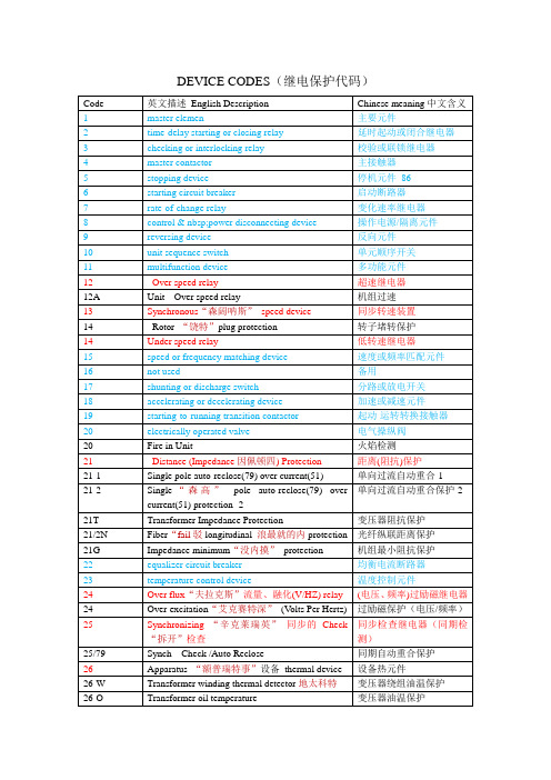
IEEE标准中综保数字代码的含义
63
Penstock Pressure Low Trip
变压器压力释放保护
63-1
Buchholz“巴克奥斯”relay / Alarm (BAL)
气体继电器/报警
63-2
Buchholz relay / Trip (BTR)
气体继电器(瓦斯)/跳闸
63R
Pressure relief relay
励磁继电器
57
short-circuiting or grounding device
短路或接地元件
58
rectification“2特菲克特申”failure relay
整流故障继电器
586A
Line Trip Circuit 1
线路跳闸回路1
586B
Line Trip Circuit 2
线路跳闸回路2
复合电压闭锁过流保护
52
ACcircuit breaker
交流断路器
53
exciter orDCgenerator relay
励磁机或直流发电机继电
54
turning gear engaging device
盘车装置啮合元件
55
power factor relay
功率因数继电器
56
field application relay
同步转速装置
14
Rotor“饶特”plug protection
转子堵转保护
14
Under speed relay
低转速继电器
15
speed or frequency matching device
速度或频率匹配元件
IEEE标准列表
IEEE NESCIR551-2009
IEEE NESCIR550-2008 IEEE NESCIR549-2008 IEEE NESCIR548-2009 IEEE NESCIR547-2008 IEEE NESCIR546-2007 IEEE NESCIR545-2007 IEEE NESCIR544-2007 IEEE N42.48-2008
IEEE 1636.2-2010
IEEE 1609.4-2010 IEEE 1410-2010 IEEE C 63.10-2009 IEEE C 57.19.00 Errata-2010 IEEE C 57.12.00-2010 IEEE C 37.90.1 Errata-2003 IEEE C 37.46-2010 IEEE C 37.239-2010 IEEE C 37.13.1a-2010 IEEE 82 Errata-2009
第38节:法规384C设备接地与连接
第21节.法规215C1非载流部件的一般要求.总论
说明.第21节:电路、支撑结构和设备的接地 215C5b规则的一般要求.非流动运输部分
第21节:法规215C1接地电路、支持结构和设备的 一般要求.非载流部件.总论
第26节:强度要求 说明.第1节:现有设备的国家电气安全规程规则 013B3应用(2007版本,第2页)(26-3-2009) IR548
应用在电力输电和配电系统中的大功率电子器件 (1 MW或更大)控制结构用指南
38 kV以上高架配电系统野生动物防护设施的电 气,机械和耐用性能测试指南
降低鸟类引起的断电指南
IEEE standard for Terminology and Test methods for ADC Std 1241-2000
IEEE Std1241-2000 IEEE Standard for Terminology and Test Methods for Analog-to-Digital ConvertersSponsorWaveform Measurement and Analysis Technical Committeeof theof theIEEE Instrumentation and Measurement SocietyApproved7December2000IEEE-SA Standards BoardAbstract:IEEE Std1241-2000identifies analog-to-digital converter(ADC)error sources and provides test methods with which to perform the required error measurements.The information in this standard is useful both to manufacturers and to users of ADCs in that it provides a basis for evaluating and comparing existing devices,as well as providing a template for writing specifications for the procurement of new ones.In some applications,the information provided by the tests described in this standard can be used to correct ADC errors, e.g.,correction for gain and offset errors.This standard also presents terminology and definitions to aid the user in defining and testing ADCs.Keywords:ADC,A/D converter,analog-to-digital converter,digitizer,terminology,test methodsThe Institute of Electrical and Electronics Engineers,Inc.3Park Avenue,New York,NY10016-5997,USACopyrightß2001by the Institute of Electrical and Electronics Engineers,Inc.All rights reserved. Published 13 June 2001. Printed in the United States of America.Print:ISBN0-7381-2724-8SH94902PDF:ISBN0-7381-2725-6SS94902No part of this publication may be reproduced in any form,in an electronic retrieval system or otherwise,without the prior written permission of the publisher.IEEE Standards documents are developed within the IEEE Societies and the Standards Coordinating Committees of the IEEE Standards Association(IEEE-SA)Standards Board.The IEEE develops its standards through a consensus development process,approved by the American National Standards Institute,which brings together volunteers representing varied viewpoints and interests to achieve thefinal product.Volunteers are not necessarily members of the Institute and serve without compensation.While the IEEE administers the process and establishes rules to promote fairness in the consensus development process,the IEEE does not independently evaluate,test,or verify the accuracy of any of the information contained in its standards.Use of an IEEE Standard is wholly voluntary.The IEEE disclaims liability for any personal injury,property or other damage,of any nature whatsoever,whether special,indirect,consequential,or compensatory,directly or indirectly resulting from the publication,use of,or reliance upon this,or any other IEEE Standard document.The IEEE does not warrant or represent the accuracy or content of the material contained herein,and expressly disclaims any express or implied warranty,including any implied warranty of merchantability orfitness for a specific purpose,or that the use of the material contained herein is free from patent infringement.IEEE Standards documents are supplied‘‘AS IS.’’The existence of an IEEE Standard does not imply that there are no other ways to produce,test,measure,purchase, market,or provide other goods and services related to the scope of the IEEE Standard.Furthermore,the viewpoint expressed at the time a standard is approved and issued is subject to change brought about through developments in the state of the art and comments received from users of the standard.Every IEEE Standard is subjected to review at least everyfive years for revision or reaffirmation.When a document is more thanfive years old and has not been reaffirmed,it is reasonable to conclude that its contents,although still of some value,do not wholly reflect the present state of the art. Users are cautioned to check to determine that they have the latest edition of any IEEE Standard.In publishing and making this document available,the IEEE is not suggesting or rendering professional or other services for,or on behalf of,any person or entity.Nor is the IEEE undertaking to perform any duty owed by any other person or entity to another.Any person utilizing this,and any other IEEE Standards document,should rely upon the advice of a competent professional in determining the exercise of reasonable care in any given circumstances.Interpretations:Occasionally questions may arise regarding the meaning of portions of standards as they relate to specific applications.When the need for interpretations is brought to the attention of IEEE,the Institute will initiate action to prepare appropriate responses.Since IEEE Standards represent a consensus of concerned interests,it is important to ensure that any interpretation has also received the concurrence of a balance of interests.For this reason, IEEE and the members of its societies and Standards Coordinating Committees are not able to provide an instant response to interpretation requests except in those cases where the matter has previously received formal consideration. Comments for revision of IEEE Standards are welcome from any interested party,regardless of membership affiliation with IEEE.Suggestions for changes in documents should be in the form of a proposed change of text,together with appropriate supporting ments on standards and requests for interpretations should be addressed to:Secretary,IEEE-SA Standards Board445Hoes LaneP.O.Box1331Piscataway,NJ08855-1331USANote:Attention is called to the possibility that implementation of this standard may require use of subjectmatter covered by patent rights.By publication of this standard,no position is taken with respect to theexistence or validity of any patent rights in connection therewith.The IEEE shall not be responsible foridentifying patents for which a license may be required by an IEEE standard or for conducting inquiriesinto the legal validity or scope of those patents that are brought to its attention.IEEE is the sole entity that may authorize the use of certification marks,trademarks,or other designations to indicate compliance with the materials set forth herein.Authorization to photocopy portions of any individual standard for internal or personal use is granted by the Institute of Electrical and Electronics Engineers,Inc.,provided that the appropriate fee is paid to Copyright Clearance Center. To arrange for payment of licensing fee,please contact Copyright Clearance Center,Customer Service,222Rosewood Drive,Danvers,MA01923USA;(978)750-8400.Permission to photocopy portions of any individual standard for educational classroom use can also be obtained through the Copyright Clearance Center.Introduction(This introduction is not a part of IEEE Std1241-2000,IEEE Standard for Terminology and Test Methods for Analog-to-Digital Converters.)This standard defines the terms,definitions,and test methods used to specify,characterize,and test analog-to-digital converters(ADCs).It is intended for the following:—Individuals and organizations who specify ADCs to be purchased—Individuals and organizations who purchase ADCs to be applied in their products —Individuals and organizations whose responsibility is to characterize and write reports on ADCs available for use in specific applications—Suppliers interested in providing high-quality and high-performance ADCs to acquirersThis standard is designed to help organizations and individuals—Incorporate quality considerations during the definition,evaluation,selection,and acceptance of supplier ADCs for operational use in their equipment—Determine how supplier ADCs should be evaluated,tested,and accepted for delivery to end users This standard is intended to satisfy the following objectives:—Promote consistency within organizations in acquiring third-party ADCs from component suppliers—Provide useful practices on including quality considerations during acquisition planning —Provide useful practices on evaluating and qualifying supplier capabilities to meet user requirements—Provide useful practices on evaluating and qualifying supplier ADCs—Assist individuals and organizations judging the quality and suitability of supplier ADCs for referral to end usersSeveral standards have previously been written that address the testing of analog-to-digital converters either directly or indirectly.These include—IEEE Std1057-1994a,which describes the testing of waveform recorders.This standard has been used as a guide for many of the techniques described in this standard.—IEEE Std746-1984[B16]b,which addresses the testing of analog-to-digital and digital-to-analog converters used for PCM television video signal processing.—JESD99-1[B21],which deals with the terms and definitions used to describe analog-to-digital and digital-to-analog converters.This standard does not include test methods.IEEE Std1241-2000for analog-to-digital converters is intended to focus specifically on terms and definitions as well as test methods for ADCs for a wide range of applications.a Information on references can be found in Clause2.b The numbers in brackets correspond to those in the bibliography in Annex C.As of October2000,the working group had the following membership:Steve Tilden,ChairPhilip Green,Secretary&Text EditorW.Thomas Meyer,Figures EditorPasquale Arpaia Giovanni Chiorboli Tom Linnenbrink*B.N.Suresh Babu Pasquale Daponte Solomon MaxAllan Belcher David Hansen Carlo MorandiDavid Bergman Fred Irons Bill PetersonEric Blom Dan Kien Pierre-Yves RoyDan Knierim*Chairman,TC-10CommitteeContributions were also made in prior years by:Jerry Blair John Deyst Norris NahmanWilliam Boyer Richard Kromer Otis M.SolomonSteve Broadstone Yves Langard T.Michael SoudersThe following members of the balloting committee voted on this standard:Pasquale Arpaia Pasquale Daponte W.Thomas MeyerSuresh Babu Philip Green Carlo MorandiEric Blom Fred Irons William E.PetersonSteven Broadstone Dan Knierim Pierre-Yves RoyGiovanni Chiorboli T.E.Linnenbrink Steven J.TildenSolomon MaxWhen the IEEE-SA Standards Board approved this standard on21September2000,it had the following membership:Donald N.Heirman,ChairJames T.Carlo,Vice-ChairJudith Gorman,SecretarySatish K.Aggarwal James H.Gurney James W.MooreMark D.Bowman Richard J.Holleman Robert F.MunznerGary R.Engmann Lowell G.Johnson Ronald C.PetersenHarold E.Epstein Robert J.Kennelly Gerald H.Petersonndis Floyd Joseph L.Koepfinger*John B.PoseyJay Forster*Peter H.Lips Gary S.RobinsonHoward M.Frazier L.Bruce McClung Akio TojoRuben D.Garzon Daleep C.Mohla Donald W.Zipse*Member EmeritusAlso included are the following nonvoting IEEE-SA Standards Board liaisons:Alan Cookson,NIST RepresentativeDonald R.Volzka,TAB RepresentativeDon MessinaIEEE Standards Project EditorContents1.Overview (1)1.1Scope (1)1.2Analog-to-digital converter background (2)1.3Guidance to the user (3)1.4Manufacturer-supplied information (5)2.References (7)3.Definitions and symbols (7)3.1Definitions (7)3.2Symbols and acronyms (14)4.Test methods (18)4.1General (18)4.2Analog input (41)4.3Static gain and offset (43)4.4Linearity (44)4.5Noise(total) (51)4.6Step response parameters (63)4.7Frequency response parameters (66)4.8Differential gain and phase (71)4.9Aperture effects (76)4.10Digital logic signals (78)4.11Pipeline delay (78)4.12Out-of-range recovery (78)4.13Word error rate (79)4.14Differential input specifications (81)4.15Comments on reference signals (82)4.16Power supply parameters (83)Annex A(informative)Comment on errors associated with word-error-rate measurement (84)Annex B(informative)Testing an ADC linearized with pseudorandom dither (86)Annex C(informative)Bibliography (90)IEEE Standard for Terminology and Test Methods for Analog-to-Digital Converters1.OverviewThis standard is divided into four clauses plus annexes.Clause1is a basic orientation.For further investigation,users of this standard can consult Clause2,which contains references to other IEEE standards on waveform measurement and relevant International Standardization Organization(ISO) documents.The definitions of technical terms and symbols used in this standard are presented in Clause3.Clause4presents a wide range of tests that measure the performance of an analog-to-digital converter.Annexes,containing the bibliography and informative comments on the tests presented in Clause4,augment the standard.1.1ScopeThe material presented in this standard is intended to provide common terminology and test methods for the testing and evaluation of analog-to-digital converters(ADCs).This standard considers only those ADCs whose output values have discrete values at discrete times,i.e., they are quantized and sampled.In general,this quantization is assumed to be nominally uniform(the input–output transfer curve is approximately a straight line)as discussed further in 1.3,and the sampling is assumed to be at a nominally uniform rate.Some but not all of the test methods in this standard can be used for ADCs that are designed for non-uniform quantization.This standard identifies ADC error sources and provides test methods with which to perform the required error measurements.The information in this standard is useful both to manufacturers and to users of ADCs in that it provides a basis for evaluating and comparing existing devices,as well as providing a template for writing specifications for the procurement of new ones.In some applications, the information provided by the tests described in this standard can be used to correct ADC errors, e.g.,correction for gain and offset errors.The reader should note that this standard has many similarities to IEEE Std1057-1994.Many of the tests and terms are nearly the same,since ADCs are a necessary part of digitizing waveform recorders.IEEEStd1241-2000IEEE STANDARD FOR TERMINOLOGY AND TEST METHODS 1.2Analog-to-digital converter backgroundThis standard considers only those ADCs whose output values have discrete values at discrete times, i.e.,they are quantized and sampled.Although different methods exist for representing a continuous analog signal as a discrete sequence of binary words,an underlying model implicit in many of the tests in this standard assumes that the relationship between the input signal and the output values approximates the staircase transfer curve depicted in Figure1a.Applying this model to a voltage-input ADC,the full-scale input range(FS)at the ADC is divided into uniform intervals,known as code bins, with nominal width Q.The number of code transition levels in the discrete transfer function is equal to 2NÀ1,where N is the number of digitized bits of the ADC.Note that there are ADCs that are designed such that N is not an integer,i.e.,the number of code transition levels is not an integral power of two. Inputs below thefirst transition or above the last transition are represented by the most negative and positive output codes,respectively.Note,however,that two conventions exist for relating V min and V max to the nominal transition points between code levels,mid-tread and mid-riser.The dotted lines at V min,V max,and(V minþV max)/2indicate what is often called the mid-tread convention,where thefirst transition is Q/2above V min and the last transition is3Q/2,below V max. This convention gets its name from the fact that the midpoint of the range,(V minþV max)/2,occurs in the middle of a code,i.e.,on the tread of the staircase transfer function.The second convention,called the mid-riser convention,is indicated in thefigure by dashed lines at V min,V max,and(V minþV max)/2. In this convention,V min isÀQ from thefirst transition,V max isþQ from the last transition,and the midpoint,(V minþV max)/2,occurs on a staircase riser.The difference between the two conventions is a displacement along the voltage axis by an amount Q/2.For all tests in this standard,this displacement has no effect on the results and either convention may be used.The one place where it does matter is when a device provides or expects user-provided reference signals.In this case the manufacturer must provide the necessary information relating the reference levels to the code transitions.In both conventions the number of code transitions is 2NÀ1and the full-scale range,FSR,is from V min to V max.Even in an ideal ADC,the quantization process produces errors.These errors contribute to the difference between the actual transfer curve and the ideal straight-line transfer curve,which is plotted as a function of the input signal in Figure1b.To use this standard,the user must understand how the transfer function maps its input values to output codewords,and how these output codewords are converted to the code bin numbering convention used in this standard.As shown in Figure1a,the lowest code bin is numbered0, the next is1,and so on up to the highest code bin,numbered(2NÀ1).In addition to unsigned binary(Figure1a),ADCs may use2’s complement,sign-magnitude,Gray,Binary-Coded-Decimal (BCD),or other output coding schemes.In these cases,a simple mapping of the ADC’s consecutive output codes to the unsigned binary codes can be used in applying various tests in this standard.Note that in the case of an ADC whose number of distinct output codes is not an integral power of2(e.g.,a BCD-coded ADC),the number of digitized bits N is still defined,but will not be an integer.Real ADCs have other errors in addition to the nominal quantization error shown in Figure1b.All errors can be divided into the categories of static and dynamic,depending on the rate of change of the input signal at the time of digitization.A slowly varying input can be considered a static signal if its effects are equivalent to those of a constant signal.Static errors,which include the quantization error, usually result from non-ideal spacing of the code transition levels.Dynamic errors occur because of additional sources of error induced by the time variation of the analog signal being sampled.Sources include harmonic distortion from the analog input stages,signal-dependent variations in the time of samples,dynamic effects in internal amplifier and comparator stages,and frequency-dependent variation in the spacing of the quantization levels.1.3Guidance to the user1.3.1InterfacingADCs present unique interfacing challenges,and without careful attention users can experience substandard results.As with all mixed-signal devices,ADCs perform as expected only when the analog and digital domains are brought together in a well-controlled fashion.The user should fully understand the manufacturer’s recommendations with regard to proper signal buffering and loading,input signal connections,transmission line matching,circuit layout patterns,power supply decoupling,and operating conditions.Edge characteristics for start-convert pulse(s)and clock(s)must be carefully chosen to ensure that input signal purity is maintained with sufficient margin up to the analog input pin(s).Most manufacturers now provide excellent ADC evaluation boards,which demonstrate IN P U T IN P U T(a)Figure 1—Staircase ADC transfer function,having full-scale range FSR and 2N À1levels,corresponding to N -bit quantizationIEEE FOR ANALOG-TO-DIGITAL CONVERTERS Std 1241-2000IEEEStd1241-2000IEEE STANDARD FOR TERMINOLOGY AND TEST METHODS recommended layout techniques,signal conditioning,and interfacing for their ADCs.If the characteristics of a new ADC are not well understood,then these boards should be analyzed or used before starting a new layout.1.3.2Test conditionsADC test specifications can be split into two groups:test conditions and test results.Typical examples of the former are:temperature,power supply voltages,clock frequency,and reference voltages. Examples of the latter are:power dissipation,effective number of bits,spurious free dynamic range (SFDR),and integral non-linearity(INL).The test methods defined in this standard describe the measurement of test results for given test conditions.ADC specification sheets will often give allowed ranges for some test condition(e.g.,power supply ranges).This implies that the ADC will function properly and that the test results will fall within their specified ranges for all test conditions within their specified ranges.Since the test condition ranges are generally specified in continuous intervals,they describe an infinite number of possible test conditions,which obviously cannot be exhaustively tested.It is up to the manufacturer or tester of an ADC to determine from design knowledge and/or testing the effect of the test conditions on the test result,and from there to determine the appropriate set of test conditions needed to accurately characterize the range of test results.For example,knowledge of the design may be sufficient to know that the highest power dissipation(test result)will occur at the highest power supply voltage(test condition),so the power dissipation test need be run only at the high end of the supply voltage range to check that the dissipation is within the maximum of its specified range.It is very important that relevant test conditions be stated when presenting test results.1.3.3Test equipmentOne must ensure that the performance of the test equipment used for these tests significantly exceeds the desired performance of the ADC under ers will likely need to include additional signal conditioning in the form offilters and pulse shapers.Accessories such as terminators, attenuators,delay lines,and other such devices are usually needed to match signal levels and to provide signal isolation to avoid corrupting the input stimuli.Quality testing requires following established procedures,most notably those specified in ISO9001: 2000[B18].In particular,traceability of instrumental calibration to a known standard is important. Commonly used test setups are described in4.1.1.1.3.4Test selectionWhen choosing which parameters to measure,one should follow the outline and hints in this clause to develop a procedure that logically and efficiently performs all needed tests on each unique setup. The standard has been designed to facilitate the development of these test procedures.In this standard the discrete Fourier transform(DFT)is used extensively for the extraction of frequency domain parameters because it provides numerous evaluation parameters from a single data record.DFT testing is the most prevalent technique used in the ADC manufacturing community,although the sine-fit test, also described in the standard,provides meaningful data.Nearly every user requires that the ADC should meet or exceed a minimum signal-to-noise-and-distortion ratio(SINAD)limit for the application and that the nonlinearity of the ADC be well understood.Certainly,the extent to whichthis standard is applied will depend upon the application;hence,the procedure should be tailored for each unique characterization plan.1.4Manufacturer-supplied information1.4.1General informationManufacturers shall supply the following general information:a)Model numberb)Physical characteristics:dimensions,packaging,pinoutsc)Power requirementsd)Environmental conditions:Safe operating,non-operating,and specified performance tempera-ture range;altitude limitations;humidity limits,operating and storage;vibration tolerance;and compliance with applicable electromagnetic interference specificationse)Any special or peculiar characteristicsf)Compliance with other specificationsg)Calibration interval,if required by ISO10012-2:1997[B19]h)Control signal characteristicsi)Output signal characteristicsj)Pipeline delay(if any)k)Exceptions to the above parameters where applicable1.4.2Minimum specificationsThe manufacturer shall provide the following specifications(see Clause3for definitions):a)Number of digitized bitsb)Range of allowable sample ratesc)Analog bandwidthd)Input signal full-scale range with nominal reference signal levelse)Input impedancef)Reference signal levels to be appliedg)Supply voltagesh)Supply currents(max,typ)i)Power dissipation(max,typ)1.4.3Additional specificationsa)Gain errorb)Offset errorc)Differential nonlinearityd)Harmonic distortion and spurious responsee)Integral nonlinearityf)Maximum static errorg)Signal-to-noise ratioh)Effective bitsi)Random noisej)Frequency responsek)Settling timel)Transition duration of step response(rise time)m)Slew rate limitn)Overshoot and precursorso)Aperture uncertainty(short-term time-base instability)p)Crosstalkq)Monotonicityr)Hysteresiss)Out-of-range recoveryt)Word error rateu)Common-mode rejection ratiov)Maximum common-mode signal levelw)Differential input impedancex)Intermodulation distortiony)Noise power ratioz)Differential gain and phase1.4.4Critical ADC parametersTable1is presented as a guide for many of the most common ADC applications.The wide range of ADC applications makes a comprehensive listing impossible.This table is intended to be a helpful starting point for users to apply this standard to their particular applications.Table1—Critical ADC parametersTypical applications Critical ADC parameters Performance issuesAudio SINAD,THD Power consumption.Crosstalk and gain matching.Automatic control MonotonicityShort-term settling,long-term stability Transfer function. Crosstalk and gain matching. Temperature stability.Digital oscilloscope/waveform recorder SINAD,ENOBBandwidthOut-of-range recoveryWord error rateSINAD for wide bandwidthamplitude resolution.Low thermal noise for repeatability.Bit error rate.Geophysical THD,SINAD,long-term stability Millihertz response.Image processing DNL,INL,SINAD,ENOBOut-of-range recoveryFull-scale step response DNL for sharp-edge detection. High-resolution at switching rate. Recovery for blooming.Radar and sonar SINAD,IMD,ENOBSFDROut-of-range recovery SINAD and IMD for clutter cancellation and Doppler processing.Spectrum analysis SINAD,ENOBSFDR SINAD and SFDR for high linear dynamic range measurements.Spread spectrum communication SINAD,IMD,ENOBSFDR,NPRNoise-to-distortion ratioIMD for quantization of smallsignals in a strong interferenceenvironment.SFDR for spatialfiltering.NPR for interchannel crosstalk.Telecommunication personal communications SINAD,NPR,SFDR,IMDBit error rateWord error rateWide input bandwidth channel bank.Interchannel crosstalk.Compression.Power consumption.Std1241-2000IEEE STANDARD FOR TERMINOLOGY AND TEST METHODS2.ReferencesThis standard shall be used in conjunction with the following publications.When the following specifications are superseded by an approved revision,the revision shall apply.IEC 60469-2(1987-12),Pulse measurement and analysis,general considerations.1IEEE Std 1057-1994,IEEE Standard for Digitizing Waveform Recorders.23.Definitions and symbolsFor the purposes of this standard,the following terms and definitions apply.The Authoritative Dictionary of IEEE Standards Terms [B15]should be referenced for terms not defined in this clause.3.1Definitions3.1.1AC-coupled analog-to-digital converter:An analog-to-digital converter utilizing a network which passes only the varying ac portion,not the static dc portion,of the analog input signal to the quantizer.3.1.2alternation band:The range of input levels which causes the converter output to alternate between two adjacent codes.A property of some analog-to-digital converters,it is the complement of the hysteresis property.3.1.3analog-to-digital converter (ADC):A device that converts a continuous time signal into a discrete-time discrete-amplitude signal.3.1.4aperture delay:The delay from a threshold crossing of the analog-to-digital converter clock which causes a sample of the analog input to be taken to the center of the aperture for that sample.COMINT ¼communications intelligence DNL ¼differential nonlinearity ENOB ¼effective number of bits ELINT ¼electronic intelligence NPR ¼noise power ratio INL ¼integral nonlinearity DG ¼differential gain errorSIGINT ¼signal intelligenceSINAD ¼signal-to-noise and distortion ratio THD ¼total harmonic distortion IMD ¼intermodulation distortion SFDR ¼spurious free dynamic range DP ¼differential phase errorTable 1—Critical ADC parameters (continued)Typical applicationsCritical ADC parametersPerformance issuesVideoDNL,SINAD,SFDR,DG,DP Differential gain and phase errors.Frequency response.Wideband digital receivers SIGINT,ELINT,COMINTSFDR,IMD SINADLinear dynamic range fordetection of low-level signals in a strong interference environment.Sampling frequency.1IEC publications are available from IEC Sales Department,Case Postale 131,3rue de Varemb,CH 1211,Gen ve 20,Switzerland/Suisse (http://www.iec.ch).IEC publications are also available in the United States from the Sales Department,American National Standards Institute,25W.43rd Street,Fourth Floor,New York,NY 10036,USA ().2IEEE publications are available from the Institute of Electrical and Electronics Engineers,445Hoes Lane,P.O.Box 1331,Piscataway,NJ 08855-1331,USA (/).。
导线分流器技术标准
导线分流器技术标准
导线分流器技术标准是指对导线分流器的设计、制造、安装和使用等各个方面所规定的要求和规范。
以下是一些常见的导线分流器技术标准:
1. IEC 61643-21:针对低压配电系统中的导线分流器的标准,
涵盖了产品的分类、工作原理、设计要求、性能测试方法等内容。
2. GB/T 18802.21:中国国家标准,与IEC 61643-21相对应,
规定了导线分流器的技术要求和测试方法。
3. UL 1449:美国标准,主要涉及电力系统的过电压保护设备,其中包括了导线分流器的要求和测试方法。
4. IEEE C62.41:由美国电气和电子工程师学会(IEEE)发布
的标准,主要用于指导电力系统中过电压保护设备的选择、安装和测试,包括导线分流器等设备。
5. DIN VDE 0675-6:德国标准,规定了低压电气装置的过电
压保护装置的要求和测试方法,适用于导线分流器等设备。
这些标准不仅规定了导线分流器的基本技术要求,还包括了产品的安装、维护、检测和使用方面的规范,确保导线分流器在正常工作条件下具有可靠的过电压保护功能,并对电力系统的稳定性和安全性起到有效的保障作用。
sae as1241d标准
SAE AS1241D标准一、范围本标准规定了汽车零件的耐腐蚀性能、耐磨损性能、耐疲劳性能、耐高温性能、耐低温性能、耐候性能、耐化学性能以及尺寸和公差等方面的要求。
本标准适用于汽车行业中各种类型的汽车零件,包括金属、塑料、橡胶等材料制成的零件。
二、术语和定义1. 耐腐蚀性能:指汽车零件在各种腐蚀介质中的抗腐蚀能力。
2. 耐磨损性能:指汽车零件在摩擦、冲击等作用下的抗磨损能力。
3. 耐疲劳性能:指汽车零件在循环载荷、温度变化等作用下的抗疲劳能力。
4. 耐高温性能:指汽车零件在高温环境下的稳定性和性能保持能力。
5. 耐低温性能:指汽车零件在低温环境下的稳定性和性能保持能力。
6. 耐候性能:指汽车零件在不同气候条件下的稳定性和性能保持能力。
7. 耐化学性能:指汽车零件在各种化学介质中的稳定性和性能保持能力。
8. 尺寸和公差:指汽车零件的制造尺寸和公差要求,以保证零件的互换性和装配精度。
三、汽车零件的耐腐蚀性能要求根据汽车零件的使用环境和介质条件,可以分为以下几种情况:1. 一般耐腐蚀要求:适用于大部分汽车零件,要求在正常使用条件下,零件表面无明显腐蚀现象,不严重影响零件的外观和性能。
2. 高耐腐蚀要求:适用于某些特殊用途的汽车零件,如排气管、油箱等,要求在严酷的腐蚀介质中仍能保持良好的抗腐蚀能力。
四、汽车零件的耐磨损性能要求根据汽车零件的不同用途和摩擦条件,可以分为以下几种情况:1. 一般耐磨要求:适用于大部分汽车零件,要求在正常使用条件下,零件具有一定的抗磨损能力,不出现明显的磨损和损伤现象。
2. 高耐磨要求:适用于某些特殊用途的汽车零件,如制动器摩擦片、传动轴等,要求具有高抗磨损能力和长寿命。
五、汽车零件的耐疲劳性能要求根据汽车零件的不同用途和受力条件,可以分为以下几种情况:1. 一般疲劳要求:适用于大部分汽车零件,要求在正常使用条件下,零件具有一定的抗疲劳能力,不出现明显的疲劳断裂和损伤现象。
2. 高疲劳要求:适用于某些特殊用途的汽车零件,如曲轴、连杆等关键部件,要求具有高抗疲劳能力和长寿命。
- 1、下载文档前请自行甄别文档内容的完整性,平台不提供额外的编辑、内容补充、找答案等附加服务。
- 2、"仅部分预览"的文档,不可在线预览部分如存在完整性等问题,可反馈申请退款(可完整预览的文档不适用该条件!)。
- 3、如文档侵犯您的权益,请联系客服反馈,我们会尽快为您处理(人工客服工作时间:9:00-18:30)。
IEEE 1241标准是一个关于电子设备中电源管理和系统管理的重要标准。
它提供了许多关于电源系统设计、性能和可靠性的指导原则。
以下是对IEEE 1241标准的800字回答:
一、简介
IEEE 1241标准是由电气和电子工程师协会(IEEE)发布的一系列电源管理标准,旨在规范电子设备的电源管理系统的设计和实施。
这些标准包括电源管理系统的性能、可靠性和可维护性等方面的要求。
二、主要内容
1. 电源管理系统设计原则
IEEE 1241标准强调了电源管理系统设计的重要性,包括电源电压的选择、电源系统的性能指标、电源转换效率、功率因数校正等方面。
此外,该标准还提出了电源系统的可靠性设计要求,包括过电流保护、过电压保护、过温保护等。
2. 电源管理系统的性能指标
IEEE 1241标准规定了电源管理系统的主要性能指标,包括电压精度、纹波抑制、瞬态响应、噪声抑制等。
这些指标对于确保电子设备的稳定运行和降低功耗具有重要意义。
3. 电源管理系统的可靠性和可维护性
该标准强调了电源管理系统的可靠性和可维护性,包括电源系统的故障检测和诊断、电源故障隔离、电源系统的备份和冗余等。
此外,该标准还提出了电源系统的可维护性要求,包括易于安装和拆卸、易于诊断和修复等。
三、应用场景
IEEE 1241标准适用于各种电子设备,如计算机、通信设备、消费电子产品、医疗设备等。
这些设备需要高效的电源管理系统来确保设备的稳定运行和降低功耗,从而提高设备的性能和可靠性。
四、优势和不足
IEEE 1241标准的优势在于它提供了一套统一的电源管理系统设计规范,有助于确保电子设备的电源管理系统的性能和可靠性。
此外,该标准还强调了电源管理系统的可维护性,有助于提高设备的可维护性和用户满意度。
然而,IEEE 1241标准也存在一些不足。
首先,该标准主要关注电源管理系统的设计和性能指标,而对于电源系统的成本和能耗等方面的考虑较少。
其次,该标准对于电源管理系统的安全性和电磁兼容性等方面的要求较少,需要其他标准和规范的支持。
五、结论
综上所述,IEEE 1241标准是一个重要的电源管理标准,对于电子设备的稳定运行和降低功耗具有重要意义。
该标准提供了一套统一的电源管理系统设计规范,有助于提高设备的性能和可靠性。
然而,该标准也存在一些不足,需要进一步完善和扩展。