zigbee协议sniffer Zigbee协议分析仪(780M)
实验-ZigBee组网
实验-ZigBee组⽹实验:ZigBee基本通信实验⼀、实验⽬的1.了解ZigBee协议及其在软件上如何实现。
2.学习使⽤sniffer嗅探⽹络节点之间通信数据包并分析数据包。
3. 学习Zigbee⽹络组⽹及路由选择。
⼆、实验内容1.基于z-stack协议栈的组⽹及数据传输。
2.使⽤sniffer抓取节点之间传输的数据包并分析数据包组成。
三、实验设备1.IAR开发平台环境2.ZigBee开发套件3.Sniffer抓包⼯具(软件和硬件)实验开发套件的领取注意事项:1、每周五上午1-2节可到电信5号楼东303A房间,协同创新中⼼找蓝伟涛学长(领取FPGA开发板)或电信1号楼515室找赵曜学长(领取Zigbee开发套件)。
2、每个⼩组以组长为代表签字领取⼀套开发套件,并在三周内归还。
请爱护实验套件,归还时确保所有部件完好齐全。
3、实验中若有问题可在周五上午1-2节课时间去上述地址找两位助教答疑。
四、实验原理1,ZigBee协议概述ZigBee作为⼀种⽆线通信标准,它是以IEEE802.15.4⽆线通信技术为基础的⼀组涉及到⽹络、安全和应⽤⽅⾯的软件协议。
它是⼀种短距离、低复杂度、低功耗、地数据传输速率和低成本的双向⽆线通信技术。
该技术可以应⽤于超低功耗率损耗的⽆线⽹络中,它满⾜ISO/OSI参考模型。
其物理层和MAC层采⽤了IEEE802.15.4标准;ZigBee联盟定义了上层部分,包括⽹络层和应⽤层。
⽆线通信⽹络软件以z-stack作为ZigBee的协议栈,硬件为基于CC2530-ZigBee开发套件。
2 设备类型(Device Types)在ZigBee⽹络中存在三种逻辑设备类型:Coordinator(协调器),Router(路由器)和End-Device(终端设备)。
ZigBee⽹络由⼀个Coordinator以及多个Router和多个End_Device组成。
在ZStack-CC2530-2.3.1-1.4.0中⼀个设备的类型通常在编译的时候通过编译选项确定。
Zigbee建网和入网过程实验

6.2 Zigbee建网和入网过程实验本实验通过Sample App这个例子实现数据在ZigBee网络中的简单传输。
要求掌握网络组建及协议分析仪的使用方法。
6.2.1 实验目的与器材1)实验目的◆熟悉zigbee协议的三种设备建网时所担任的角色;◆学习Z-Stack2007/PRO协议栈中协调器如何建立网络;◆学习Z-Stack2007/PRO协议栈中路由和终端如何加入网络;◆学习TI官方提供的抓包工具(Sniffer)的应用及协议分析。
2)实验器材◆3个CC2530开发套件(1个协调器模块,2个路由器模块);6.2.2 实验原理与步骤1)硬件介绍CC2530开发套件如实验一中的硬件介绍,这里就不再陈述。
2)实验原理1 设备的分类ZigBee网络只支持两种设备:1)全功能设备(FFD Full Function Device)2)精简功能设备(也叫半功能设备 Reduced Function Device)两者的比较:其中FFD设备能够提供MAC层的所有服务,可充当任何ZigBee节点,不仅可以接收发送数据,还具有路由功能,因此可以接收子节点;而RFD只能提供部分的MAC层服务,只能充当子节点,只负责将采集到的数据发送给协调器和路由器节点,本身并不具有路由功能,因此不能接收子节点信息,RFD之间的通信只能通过FFD来完成。
ZigBee标准在此基础上定义了三种节点:ZigBee协调器(Coordinator)、ZigBee路由器(Routers)、ZigBee终端(End Device)2 所使用的设备所用的ZigBee设备都具有连接网络和断块网路的功能。
ZigBee协调器和路由器都具有以下附加功能:1)允许设备以如下方式连接网路:① MAC(Medium Access Control)层的连接命令。
②应用层的连接请求2)允许设备以如下方式断开网络;① MAC层的断开命令②应用层的断开命令③对逻辑网络地址的分配④维护邻居设备3 组建网络组建一个网状的ZigBee网络包括两个步骤:网络的初始化和节点加入网络;而节点加入网络又有两个步骤:通过协调器加入网络和通过已有节点入网。
Zigbee知识点

第一章Zigbee概述1、Zigbee就是一种新兴的短距离、低速率无线网络技术,主要用于近距离无线连接。
2、Zigbee的特点就是功耗低、成本低、时延短、网络容量大、可靠安全。
3、常见的Zigbee芯片有CC243X系列、MC1322X系列与CC253X系列。
4、常见的Zigbee协议栈有非开源(msstatePAN)协议栈、开源(freakz)协议栈与半开源(Zstack)协议栈。
5、Zigbee软件开发平台包括IAR、Zigbee Sniffer、物理地址修改软件以及其它辅助软件。
6、Zigbee硬件开发平台采用Altium Designer进行设计。
7、简述Zigbee的定义。
答:Zigbee就是一种近距离、低复杂度、低功耗、低成本的双向无线通讯技术。
主要用于距离短、功耗低且传输速率不高的各种电子设备之间,进行数据传输(包括典型的周期性数据、间歇性数据与低反应时间数据)的应用。
( Zigbee的基础就是IEEE802、15、4,但就是IEEE802、15、4仅处理低级的MAC(媒体接入控制协议)层与物理层协议,Zigbee联盟对网络层协议与应用层进行了标准化。
)8、简述无线传感器网络与Zigbee之间的关系。
答:从协议标准来讲:目前大多数无线传感器网络的物理层与MAC层都采用IEEE802、15、4协议标准。
IEEE802、15、4描述了低速率无线个人局域网的物理层与媒体接入控制协议(MAC层),属于IEEE802、15、4工作组。
而Zigbee技术就是基于IEEE802、15、4标准的无线技术。
从应用上来讲:Zigbee适用于通信数据量不大,数据传输速率相对较低,成本较低的便携或移动设备。
这些设备只需要很少的能量,以接力的方式通过无线电波将数据从一个传感器传到另外一个传感器,并能实现传感器之间的组网,实现无线传感器网络分布式、自组织与低功耗的特点。
9、Zigbee技术特点:低功耗、低成本、大容量、可靠、时延短、灵活的网络拓扑结构。
hac-embee-a11n 2.4g 低功耗无线数传模块(zigbee)用户手册说明书
HAC-EmBee-A11D HAC-EmBee-A11N2.4G低功耗无线数传模块(ZigBee)用户手册V 2.02.2 2013/10/25深圳市华奥通通信技术有限公司SHENZHEN HAC TELECOM TECHNOLOGY CO.,LTD地址 : 深圳市南山区西丽路4227号大学城创意园2栋6楼电话 : +86-755-23981078传真 : +86-755-23981007邮件:*****************************网址 : HAC EmBee ZigBee Series 深圳市华奥通通信技术有限公司高性能✧20dbm可视距离2.8km✧7dbm可视距离850m 低功耗✧20dbm发射电流145mA,接收电流38mA,休眠电流3uA✧7dbm发射电流42mA,接收电流29mA,休眠电流3uAMESH网络✧自动组网,自动路由,自动愈合✧点对点,点对多点传输✧最多高达16跳传输 使用简单✧AT命令✧API命令✧API远程AT命令✧透明传输符合标准✧Zigbee 2007 Pro✧A11 Profile高可靠性✧DSSS O-QPSK调制方式✧CSMA-CA 自动退避机制✧重发与应答机制高安全性✧网络层AES加密✧应用层AES加密目录1 EmBee模块 (6)1.1 EmBee模块尺寸及管脚顺序 (6)1.2 模块管脚分布 (7)1.3 模块性能参数 (8)1.3.1 HAC-EmBee-A11N参数 (8)1.3.2 HAC-EmBee-A11D参数 (9)2 EmBee模块操作 (10)2.1 UART串口介绍 (10)2.2 通信协议 (10)2.2.1 透明传输模式 (10)2.2.2 API传输模式 (11)2.3 AT命令模式 (11)2.3.1 进入AT命令模式 (12)2.3.2 发送AT命令 (12)2.3.3 AT命令响应 (12)2.3.4 退出AT命令模式 (13)2.4 回环功能 (13)2.4.1 透传模式的回环 (13)2.4.2 API模式的回环 (13)3 API操作 (14)3.1 API帧格式 (14)3.2 API帧 (15)3.2.1 AT命令帧(立即生效) (15)3.2.2 AT命令帧(不立即生效) (16)3.2.3 AT命令响应帧 (17)3.2.4 传输请求帧 (18)3.2.5 应用层可选的传输请求帧 (19)3.2.6 传输状态帧 (21)3.2.1 数据接收指示帧(AO=0) (22)3.2.2 数据接收指示帧(AO=1) (23)3.2.3 I/O接收指示 (24)3.2.4 节点发现指示 (26)3.2.5 模块状态指示帧 (28)3.2.6 远端AT命令请求帧 (29)3.2.7 远端AT命令响应帧 (30)4 AT命令 (32)4.1 地址命令 (32)4.2 网络命令 (34)4.3 射频参数命令 (36)4.4 串口参数命令 (37)4.5 I/O参数命令 (38)4.6 诊断参数命令 (41)4.7 AT命令参数 (42)4.8 休眠命令 (42)4.9 命令执行 (43)5 数字I/O和模拟I/O (45)5.1 本地I/O (45)5.1.1 AT命令模式下读取本地I/O电平值和采样值 (45)5.1.1 AT命令模式下配置本地I/O (46)5.1.2 API模式下配置本地I/O (47)5.2 远端I/O (47)5.2.1 API模式下配置远端I/O (47)6 EmBee ZigBee网络 (48)6.1 协调器 (48)6.2 路由器 (49)6.3 终端设备 (49)6.3.1 子节点与父节点关系 (50)6.3.2 子节点容量 (50)6.4 子节点工作过程 (51)6.5 父节点工作过程 (51)1EmBee模块1.1EmBee模块尺寸及管脚顺序EmBee模块的外形结构如下:管脚顺序从PIN1开始,逆时针依次至PIN20。
ZIGBEE仿真器介绍
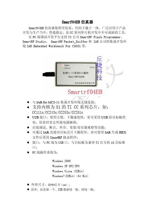
Smarf04EB 仿真器Smarf04EB 仿真器集程序仿真、代码下载于一体,广泛应用于产品 开发与生产当中,性能稳定,是 CC 系列单片机开发中不可或缺的工具。
在 PC 端调试开发平台支持 TI 公司 SmartRF Flash Programmer、 SmartRF Studio、 SmartRF Packet_Sniffer 和 IAR 公司的集成开发环 境 IAR Embedded Workbench For C8051 等。
z z z z z z z与 IAR for MCS-51 集成开发环境无缝连接;支持内核为 51 的 TI CC 系列芯片,如:CC111x/CC243x/CC253x/CC251xUSB 接口,使用方便,下载速度快,更可采用 USB 给目标板供 电,仿真时省去外接电源麻烦; 在线调试、断点、单步、变量/寄存器观察等功能; 可通过 IAR 直接对目标芯片下载程序,亦可使用 IAR 生成 HEX 文件后采用 SmartRF 烧录程序; 接口:与 PC 端为 USB 口、与目标板为兼容 TI 官方的 10 芯标准 口; PC 端操作系统为:Windows 2000 Windows XP SP2/SP3 Windows Vista (32Bit) Windows7(32Bit)(64 Bit)z 外形尺寸:10*6*2.5(cm); z 清单:仿真器一个、USB 数据线一根、排线一根;CC Debugger仿真器CC Debugger 是用于 TI 低功耗射频片上系统的小型编程器和调试 器。
它可以与用于 8051(7.51A 或更高版本)的 IAR 嵌入式工作平台一 起使用以进行调试, 并可与 SmartRF 闪存编程器一起使用以进行闪存编 程。
CC 调试器还可用于控制 SmartRF Studio 中的所选器件,或者与 CC 芯片相连, 使用 Packet Sniffer 软件进行协议分析, 是学习开发 Zigbee、 RF4CE 等无线产品的最好最实用的开发工具。
Silicon Labs ETRX 357 ZIGBEE 模块使用说明书

ETRX357 ZIGBEE® MODULESUsing R3xx Firmware in a Home Automation Network Telegesis™ is a trademark of Silicon Laboratories Inc.Table of Contents1INTRODUCTION (3)2FORMAT OF COMMANDS AND DATA IN THIS NOTE (3)3REGISTER SETTINGS AND COMMANDS (3)3.1Typical commands to start a PAN (4)3.2Typical received data (5)Device joins the network (5)Temperature reading received (5)Humidity reading received (6)3.3Send HA commands (6)3.4Intruder Alarm System devices (7)1 IntroductionThe off-the-shelf Telegesis firmware that uses our manufacturer specific profile can also be used in a Home Automation network, but several registers must first be configured in order that it can join or form a network and present incoming data. Further registers can be set if it is necessary to send HA commands and to allow endpoint 2 to properly respond to queries from other devices such as requests for active endpoints. This note presents a minimal list of the register settings and some examples of data received from a temperature/humidity sensor. For more detailed information refer to:R309 AT Command Manual (or the version that relates to your actual firmware) (SiLabs) Application Note on Interoperability (SiLabs)ZigBee Cluster Library Specification (ZigBee Alliance)ZigBee Home Automation Public Application Profile (ZigBee Alliance)Although the AT command set firmware that is normally supplied pre-loaded into the ETRX357 modules can send HA commands, it is necessary to assemble them at the byte level by reference to the ZigBee specifications, and incoming messages have to be handled by a host processor. If it is used as the coordinator in a network that includes Intruder Alarm System devices, the host also needs to supports a zone table. For these reasons it may be better to use the Telegesis HA Combined Interface firmware that has commands tailored to HA operations.2 Format of commands and data in this noteBold text: command to be typed inItalic: example data received3 Register settings and commandsThe default setting of the ETRX357’s serial port is 19200 baud, 8 data bits, no parity, 1 stop bit. This can be changed by writing a new value into register S12.The S-register settings only need to be entered once as they are mostly non-volatile. The volatile registers have an associated default setting which is applied when the device is reset. Follow the sequence of operations as given here until you are familiar with the effects of the various commands, because some of the registers must be set before the device starts or joins a network. Some of the commands are optional, such as allowing and blocking joining.3.1 Typical commands to start a PANAT+DASSL Disassociate fromprevious network ifdesiredAT&F Restore to a known stateif desiredATITelegesis ETRX357-LRS R309C000D6F0001B65311Check firmware version. It ought to be R308 or higherAT+N+N=NoPANCheck network statusATS00=6319 Home Automationchannel maskATS0A=0114;password Use predefined Link Key ATS09=5A6967426565416C6C69616E63653039;password Define HA Link KeyAT+EN Establish network ifnecessaryATS0A0=0;password Allow joining (optional,this is the default setting) ATS0A0=1;password Disallow joining when allthe sensors have joined ATSALL:FFFD,0A0=0;password Allow joining via all otherdevices in the PAN ATSALL:FFFD,0A0=1;password Block joining via any otherdevice in the PANATS0F=0104 Allow display of messagesthat arrive on endpoint 2 ATS0EA=1 Suppress display of“SR…” promptsATS0FC=1 Optional with R309. Datais shown in hexadecimalformat instead of rawcharactersRX:4B5C,0104,02,02,0402,08:••)û RX:4B5C,0104,02,02,0405,08:••!ÙRX:4B5C,0104,02,02,0402,08:18180A000029FC08 RX:4B5C,0104,02,02,0405,08:18190A000021B80ERX:4B5C,0104,02,02,0402,08:<18><03><0A><00><00>)<9F><08>RX:4B5C,0104,02,02,0405,08:<18><04><0A><00><00>!W<0F> Presentation of the raw binary characters will depend on the terminal software being used3.2 Typical received dataThese are examples of readings from a temperature and humidity sensor. The actualformat depends on the terminal software you are using, except that bit C of register S0F turns raw characters into hexadecimal format (R309 only). Note that 16-bit data arrives low-byte first.Device joins the network MED:00124B00029ACA1C,21E6 MEDA Mobile End Device has joined the network. Can also be FFD or SED00124B00029ACA1C EUI64 of new device21E6 Network address of new deviceTemperature reading receivedRX:4B5C,0104,02,02,0402,08:<18><3B><0A><00><00><29><DD><08> 4B5C Source network address 0104 HA profile ID02 Destination endpoint 02 Source endpoint0402 Temperature cluster ID 08 Number of payload bytes<18> Frame control <3B> Sequence no<0A> Cmd ID: report attributes <0000> Attribute ID: measured value <29> Type int16s<DD08> 08DD = 2269 = 22.69°Humidity reading receivedRX:4B5C,0104,02,02,0405,08:<18><3C><0A><00><00><21><35><0E>4B5C Source network address0104 HA profile ID02 Destination endpoint02 Source endpoint0405 Relative humidity cluster ID08 Number of payload bytes<18> Frame control<3C> Sequence no<0A> Cmd ID: report attributes<0000> Attribute ID: measured value<21> Type int16s<350E> 0E35 = 3637 = 36.37%3.3 Send HA commandsThese are not needed if data is only to be received. You will need these settings to configure attribute reporting, though. Most sensors that report attributes from more than one cluster seem to use the same reporting interval for all clusters, but this may not always apply especially if you set a reportable change level.ATS40=0202 Current source and destination endpoint ATS41=0202 Default source and destination endpoint ATS42=0402 Current cluster IDATS43=0402 Default cluster IDATS44=0104 Current profile IDATS45=0104 Default profile IDExample: sent 14 bytes to network address 4B5C to configure reporting interval. The actual sequence number is not important. The characters after the ‘>’ indicate the value of each byte, not the format which will depend on the terminal application in use.AT+UCASTB:0D,4B5C>00 03 06 00 00 00 29 00 00 0A 00 FF FF00 Frame control03 Sequence no06 Cmd ID: configure reporting00 Direction0000 Attribute ID29 Type int16s0000 Minimum reporting interval (off)000A Maximum reporting interval (10 secs) FFFF Reportable change (off)This approach is suitable when the endpoint and cluster ID do not change often. The R309 firmware introduces a new set of commands such as AT+SENDUCAST; these commands take the endpoints, profile and cluster ID as parameters so they can be altered with each command. The registers and command in the example above then becomeAT+SENDUCASTB:0D,4B5C,02,02,0104,0402>00 03 06 00 00 00 29 00 00 0A 00 FF FFand there is no longer any need to write new S-register values.3.4 Intruder Alarm System devicesIAS Zone devices are typically encountered as motion sensors, door/window sensors and similar products. They need to be assigned to zones when they join the network and may leave quite quickly if they do not receive suitable responses to their queries. IAS devices must enrol with the Control and Indicating Equipment (CIE) that is implemented with the R3xx firmware, so the latter needs to be configured correctly in order that the IAS device can find it. A typical sequence of operations is:In order that the CIE device can respond automatically to the Match Description Request the user must first set three S-registers:ATS0AB=1;password Allow Endpoint 2 to reply to ZDO endpoint queriesATS48=0104 Set endpoint 2 Profile ID to Home AutomationATS4C=0500 Add IAS Zone cluster to endpoint 2 Output Cluster ListThe user’s application must recognise the Zone Enroll Request (cluster 0x0500, command 0x01, server to client) and reply with a Zone Enroll Response (command 0x00, client to server) with the user’s choice of zone ID. Finally the CIE must write its own EUI64 to the IAS_CIE_address attribute of the IAS Zone device.Silicon Laboratories Inc.400 West Cesar Chavez Austin, TX 78701USASmart.Connected.Energy-FriendlyProducts/productsQuality /qualitySupport and CommunityDisclaimerSilicon Laboratories intends to provide customers with the latest, accurate, and in-depth documentation of all peripherals and modules available for system and software implementers using or intending to use the Silicon Laboratories products. Characterization data, available modules and peripherals, memory sizes and memory addresses refer to each specific device, and "Typical" parameters provided can and do vary in different applications. Application examples described herein are for illustrative purposes only. Silicon Laboratories reserves the right to make changes without further notice and limitation to product information, specifications, and descriptions herein, and does not give warranties as to the accuracy or completeness of the included information. Silicon Laboratories shall have no liability for the consequences of use of the information supplied herein. This document does not imply or express copyright licenses granted hereunder to design or fabricate any integrated circuits. The products are not designed or authorized to be used within any Life Support System without the specific written consent of Silicon Laboratories. A "Life Support System" is any product or system intended to support or sustain life and/or health, which, if it fails, can be reasonably expected to result in significant personal injury or death. Silicon Laboratories products are not designed or authorized for military applications. Silicon Laboratories products shall under no circumstances be used in weapons of mass destruction including (but not limited to) nuclear, biological or chemical weapons, or missiles capable of delivering such weapons.Trademark InformationSilicon Laboratories Inc.® , Silicon Laboratories®, Silicon Labs®, SiLabs® and the Silicon Labs logo®, Bluegiga®, Bluegiga Logo®, Clockbuilder®, CMEMS®, DSPLL®, EFM®, EFM32®, EFR, Ember®, Energy Micro, Energy Micro logo and combinations thereof, "the world’s most energy friendly microcontrollers", Ember®, EZLink®, EZRadio®, EZRadioPRO®, Gecko®, ISOmodem®, Precision32®, ProSLIC®, Simplicity Studio®, SiPHY®, Telegesis, the Telegesis Logo®, USBXpress® and others are trademarks or registered trademarks of Silicon Laborato-ries Inc. ARM, CORTEX, Cortex-M3 and THUMB are trademarks or registered trademarks of ARM Holdings. Keil is a registered trademark of ARM Limited. All other products or brand names mentioned herein are trademarks of their respective holders.。
北科大物联网方案
北京科技大学物联网教学实训方案一:面向基础课程的实验教学通过对各技术方向教学实验系统的动手操作,学生可以加深对物联网基础理论知识的了解和掌握.ATOS物联网教学实验开发系统是一款融合了传感器技术、嵌入式技术、分布式信息处理技术、无线通讯技术、网络安全技术,智能控制等一系列先进技术的物联网产品。
ATOS 实验开发系统在网络安全协议、大规模传感器网络中的节点移动性管理、网络的自组织、自愈性和系统功耗问题等一系列关键技术方面处于市场的前沿。
其包含了一整套完善的解决方案:应用决策层:AtoApp:应用决策软件,基于各种行业应用,可实现数据的远程即时获取,迅速做出决策中央服务器层:AtoServer:中央数据库服务器,存储海量传感器数据采集汇集层:AtoSink:汇聚节点网络数据,通过3G、Internet等将数据远程上传至中央服务器WSN网络:Atosenet:节点网络,自组织、自恢复、低功耗、网状路由数据感知层:AtoSensor:可接入各种标准传感器及用户自定义传感器,用于感知各种物理推荐实验室配置如下:产品型号ATOS3010F以CC2430为射频芯片的无线传感网络节点及带RFID及二维码的系统系统配置无线网络节点(CC2430)8个网关板1个USB基站1个多频段RFID读卡器1个多频段电子标签5个二维码读写器1个二维码标签2个在线烧录器1个网络分析仪1个传感器8个射频天线9个串口线、烧录线、充电器3根ATOS实验平台光盘内容包含:开发环境、源代码、实验教学体系、应用DEMO、开发工具等二:面向项目开发教学应用物联网属于前沿技术领域,具有重大的科学研究及应用价值。
基于本系统的学习,可以开发简单实用项目.让学生对所学习的内容能转化为实际应用的案例.实验室的建设将紧密结合物联网产业的发展,物联网的应用已经在食品溯源、智能建筑、智能交通、智能电网、医疗卫生等行业都有极好的应用前景.通过对物联网的实训平台,让学生了解物联网的整个应用环节,从而激发学生兴趣,培养其物联网工程应用及设计的综合能力,达到真正的学以致用。
基于ZigBee技术的无线传感器网络的研究与设计本科生毕业论文设计 精品
本科生毕业论文(设计)题目:基于ZigBee技术的无线传感器网络的研究与设计目录摘要: (IV)ABSTRACT (V)第一章绪论 (1)1.1 课题背景概述 (1)1.2 WSN简介 (2)1.2.1 WSN体系结构 (2)1.2.2 WSN的协议栈结构 (4)1.2.3 WSN特点及其关键问题 (6)1.2 几种常用的无线通信技术 (7)1.3.1 蓝牙技术 (7)1.3.2 红外技术 (7)1.3.3 ZigBee技术 (8)1.3.4 Wi-Fi技术 (8)1.3.5 RFID技术 (8)1.3.6 HomeRF技术 (9)1.3.7 UWB技术 (9)1.3.8 几种无线通信技术对比 (9)1.4 本文结构组织 (10)1.5 本章小结 (11)第二章 ZigBee/IEEE802.15.4技术标准 (12)2.1 ZigBee/IEEE802.15.4技术概述 (12)2.2 ZigBee技术特点 (12)2.3 ZigBee技术的体系结构 (13)2.4 ZigBee技术的网络配置 (15)2.4.1 两种功能设备 (15)2.4.2 三种节点类型 (15)2.4.3 三种拓扑结构 (16)2.4.4 两种工作模式 (17)2.5 ZigBee组网 (17)2.5.1 基本通信原语 (17)2.5.2 ZigBee网络的组网 (18)2.5.2.1 网络管理服务 (18)2.5.2.2 数据传输服务 (20)2.6 ZigBee 路由 (21)2.6.1路由协议 (21)2.6.2 路由过程 (22)2.7本章小结 (23)第三章基于ZigBee的无线传感器网络的硬件设计 (24)3.1 ZigBee的几种实现方案 (25)3.2 CC2430芯片介绍 (26)3.2.1 CC2430芯片概述 (26)3.2.2 CC2430引脚功能介绍 (29)3.2.3 CC2430的增强型8051内核 (31)3.2.4 CC2430的射频部分 (32)3.2.5 CC2430的其它外围设备 (34)3.2.5.1 直接存取(DMA)控制器 (34)3.2.5.2 MAC定时器 (35)3.2.5.3 模数转换器(ADC) (35)3.2.5.4 温度传感器 (36)3.3 节点的控制和显示电路 (36)3.3.1 控制电路 (37)3.3.2 状态显示电路 (38)3.4 节点的接口电路 (39)3.4.1 USART接口(串行通信接口) (40)3.4.2 JTAG接口 (40)3.5 节点实图 (41)3.6 本章小结 (41)第四章基于ZigBee2006协议栈的无线传感器网络的软件设计 (43)4.1 Z-Stack (43)4.1.1 Z-Stack软件架构 (43)4.1.1.1 系统初始化 (44)4.1.1.2 操作系统的执行 (44)4.1.2 Z-Stack项目中的文件目录 (49)4.2 Z-Stack开发软件 (51)4.2.1 IAR EW8051集成开发环境 (51)4.2.2 ZigBee2006协议栈 (52)4.2.3 SmartRF Flash Programmer软件 (54)4.2.4 ZigBee协议分析仪软件Packet Sniffer (55)4.3 Z-Stack开发的一些基本概念 (55)4.4 实验测试 (60)4.4.1 开关灯控制实验 (60)4.4.1.1 功能描述 (60)4.4.1.2 实验程序 (61)4.4.1.3 实验操作及其结果 (65)4.4.2 温度传输实验 (66)4.4.2.1 功能描述 (66)4.4.2.2 实验程序 (67)4.4.2.3 实验操作及其结果 (73)4.5 本章小结 (76)第五章总结与展望 (77)5.1 无线传感器网络的应用设想 (77)5.2 总结与展望 (78)5.2.1 本文总结 (78)5.2.2 展望 (78)参考文献 (79)附录 (80)致谢 (89)基于ZigBee技术的无线传感器网络的研究与设计作者:闫彦含指导老师:何自立摘要:无线传感器网络是涉及多学科、知识高度集中、在当今国际上备受关注的前沿热点和研究领域。
780B设备介绍
11111111
11111111
2M 业务1:7和1:3保护 34M/45M 业务两组1:3保护
FonsWeaver PRO是为 了增强ASON设备的低阶 业务下载能力设计,适 用于FonsWeaver系列产 品,共有16个业务槽位。 它能终结756个E1业务; 同时支持E1盘的一组 1:N保护和1:M保护 (N≤7;M≤3);支持 34M盘的两组1:3保护; 支持FE盘的两组1:1保 护。
ASON780B设备介绍
烽火通信科技股份有限公司 技术支援部 2008年8月
FonsWeaver780B
• FonsWeaver 780B设备作为一种多方向、多业务接口的 综合性光传输平台,它不仅可以提供全系列速率的SDH 接口和PDH接口,支持以太网及ATM业务的传输;而 且具有强大的高、低阶交叉能力;同时支持各种拓扑结 构的组网及保护。设备的各种功能和各项技术指标都遵 循ITU-T的相关标准和建议。
• 高阶交叉容量为160G(1024X1024VC4);低阶交叉容量:最大20G( 128X128VC4)
• 高阶接口盘位18个,其中10G盘位最多12个,2.5G/622M/O155M盘位最多18个 ,GFI1盘位最多17个(W2不能插);
• 低阶:2M/34M/45M/FE:主框8个盘位,扩展框16个盘位。单子框直接接入8个 VC4带宽的低阶业务(E1/FE),终结504个2M(8VC4)业务;主框和扩展 框,共可以提供1260(20VC4)个2M业务上下;
管理平面
ASON网络的三个平面
控制平面
传送平面 与现有网络相比,ASON中增加了一个控制平面,也是整个ASON网络 的核心部分。
三个平面的功能
• 传送平面
– 传送平面仍然负责业务的传送,不同之处在于传送平面的动作是在 网管平面和控制平面的作用下进行的。
09 ZigBee技术概述
31
Z-Stack协议栈软件层次
APP HAL MT
用户应用程序目录 硬件接口层目录 底层封装目录(无源码) 串口操作工具目录 操作系统抽象层目录 协议栈入口目录 设备对象层管理代码目录 工程配置文件目录(信道、PANID)
如: TI CC2420+MSP430 、FREESCLAE MC13XX+GT60 、 MICROCHIP MJ2440+PIC MCU
集成RF和MCU的单芯片SOC方案
如:TI CC2530/CC2531 、FREESCALE MC1321X 、EM250。
ZigBee协处理器和MCU的双芯片方案
8
ZigBee的版本
ZigBee 2004规范
前后不兼容
ZigBee 2006规范
完全向后兼容
ZigBee 2007规范
Stack Profile 1:目标是消费电子产品和灯光商业应用环境 Stack Profile 2:目标是商业和工业环境
9
ZigBee技术特点
数据传输速率低:20Kb/秒~250Kb /秒,专注于低传输应用。 功耗低:在低功耗待机模式下,两节普通5号电池可使用6~24个月 成本低:ZigBee数据传输速率低,协议简单,所以大大降低了成本。 网络容量大:网络可容纳65,000个设备。 时延短:通常时延都在15ms~30ms。 安全: ZigBee提供了数据完整性检查和鉴权功能,采用AES-128加密 算法。 有效范围小:有效覆盖范围10~75米,具体依据实际发射功率大小和 各种不同的应用模式而定。 传输可靠:采用碰撞避免策略,同时为需要固定带宽的业务预留专用 时隙。
- 1、下载文档前请自行甄别文档内容的完整性,平台不提供额外的编辑、内容补充、找答案等附加服务。
- 2、"仅部分预览"的文档,不可在线预览部分如存在完整性等问题,可反馈申请退款(可完整预览的文档不适用该条件!)。
- 3、如文档侵犯您的权益,请联系客服反馈,我们会尽快为您处理(人工客服工作时间:9:00-18:30)。
使用手册
——Zigbee协议分析仪
南京瀚之显电子科技有限公司
地址:南京大明路105-2秦淮科技创业中心C座2F
@2011南京瀚之显电子科技有限公司
版权所有
在没有南京瀚之显电子科技公司的优先书面授权书前提下,此出版物的任何一个部分决不可以通过任何形式进行复制、修改或者翻译。
从此文件出版日期起,在此发表的是当前的或者拟定的信息。
由于我们不断地对产品进行改进和增加特征,此出版物中的信息如有变动恕不通知。
版本作者日期备注
V1.00Liutianmin2011年6月10日初始版本
目录
系统描述 (5)
系统图片 (5)
HMD20202使用说明 (6)
1设备被连接 (6)
2驱动安装 (6)
3使用 (6)
系统名称:HMD20202Zigbee协议分析仪
系统描述:
无线传感网作为新兴产业,发展迅速,被称为全球未来的三大高科技产业之一,是21世纪最有影响的21项技术和改变世界的10大技术之一。
无线网络协议栈是无线传感网的核心组成部分,当前Zigbee协议栈是最有前景的无线网络协议栈,其所倡导的低功耗、短距离、低速率无线传输十分适合在无线传感网中应用。
虽然Zigbee协议相比于其他无线协议已经是非常简单,但无线电毕竟是看不找摸不着的,这就给Zigbee协议的开发、应用,无线传感网的组装、调试带来了极大的麻烦。
为此我公司针对此情况开发了一套780M Zigbee协议分析仪,使用它可以捕获空中一切Zigbee协议数据包,通过串口把数据传送到PC 机上显示出来,方便了开发人员分析Zigbee数据包,调试Zigbee协议。
同时本产品还给初学者学习Zigbee协议带来了方便。
系统图片:
图1展示了我公司的Zigbee协议分析仪。
图1HMD20202780MZigbee协议分析仪
HMD20202使用说明
1设备被连接
HMD20202通过USB 供电,使用时只要通过一根USB
线接到PC 机上即可对设备供电,此时HMD20202上的电源指示灯将点亮,如图1。
图1
在图中我们可以看到三个指示灯——电源指示灯、运行指示灯、接收指示灯。
电源指示灯指示HMD20202
是否正常,上电以后如果供电正常则该灯常亮;运行指示灯指示HMD20202运行是否正常,如果每隔1S 钟该灯闪烁一次则表明HMD20202运行正常;接收指示灯指示HMD20202是否接收到数据,当接收到数据包(一切Zigbee 协议包)时该灯闪烁一次。
2驱动安装
HMD20202通过USB 和电脑相连,使用前需按照下面步骤安装USB 驱动。
1)解压目录下的PL2303压缩文件。
2)双击安装文件按照指示安装下去即可。
3)安装成功后,插上USB 后将看到设备管理器的“端口”中将多出一个COM5口(注:不同的电脑安装后端口号不一定相同),此时PC 机就可以和HMD20202通信了。
图2设备管理器
COM5
3使用
1)上面驱动安装好后,打开SSCOM,按照图3所示设置,波特率为115200。
图3SSCOM串口调试工具
2)设置完毕后打开串口,此时敲一下空格HMD20202将开始执行,如图4所示。
图4HMD20202开始执行
如果输入空格后没有接收到数据,首先要查看串口设置是否正确,如果确定串口设置正确但还是接收不到数据,则要检查USB接线数否正确,如果接线也没有问题,则可能是USB驱动没有安装好需重新安装,然后重新连接电脑和HMD20202按照上面步骤重新操作。
由图4可以看到HMD20202输出了一些消息其含义如下:
第一行:说明了此设备是一个Sniffer mod;
第二行:说明了当前的channel page,由于中国所处的channel page是5,这里固定为5;
第三行:告诉我们当前信道为信道1;
第四行:提醒我们选择信道。
输入你关心的信道,这里输入3,如图5:
图5输入信道号
3)按回车就可以接收到当前空中的一切数据包了,如图6:
此时每接收到一个数据包协议分析仪左面的红灯将闪烁一次,同时将数据包发送到SSCOM上显示出来,便于分析数据包。
图6接收到的数据包
由图5可以看出NO.1是一个命令包,NO.2是一个应答包,NO.3是一个数据包,用户通过这些数据包就可以分析网络运行是否正确,给调试带来极大地方便。