四通道燃烧器说明书2010-9-6
四通道直接作用和助动阀门的应用说明书
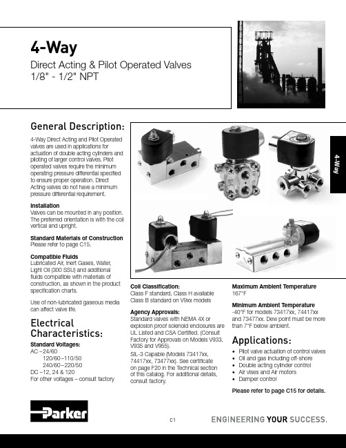
C1General Description:4-Way Direct Acting and Pilot Operated valves are used in applications foractuation of double acting cylinders and piloting of larger control valves. Pilot operated valves require the minimum operating pressure differential specified to ensure proper operation. Direct Acting valves do not have a minimum pressure differential requirement.InstallationValves can be mounted in any position. The preferred orientation is with the coil vertical and upright.Standard Materials of Construction Please refer to page C15.Compatible FluidsLubricated Air, Inert Gases, Water, Light Oil (300 SSU) and additional fluids compatible with materials of construction, as shown in the product specification charts.Use of non-lubricated gaseous media can affect valve life.ElectricalCharacteristics:Standard Voltages: AC – 24/60120/60–110/50 240/60–220/50DC – 12, 24 & 120For other voltages – consult factoryCoil Classification:Class F standard, Class H available Class B standard on V9xx models Agency Approvals:Standard valves with NEMA 4X orexplosion proof solenoid enclosures are UL Listed and CSA Certified. (Consult Factory for Approvals on Models V933, V935 and V955).SIL-3 Capable (Models 73417xx, 74417xx, 73477xx). See certificate on page F20 in the Technical section of this catalog. For additional details, consult factory.Maximum Ambient Temperature 167°FMinimum Ambient Temperature -40°F for models 73417xx, 74417xx and 73477xx. Dew point must be more than 7°F below ambient.Applications:• Pilot valve actuation of control valves • Oil and gas including off-shore • Double acting cylinder control • Air vises and Air motors •Damper controlPlease refer to page C15 for details.4-WayDirect Acting & Pilot Operated Valves 1/8" - 1/2" NPT4-WayC2Parker Hannifin Corporation Fluid Control Division180****8305(1800Valve05) /fcd43/83/160.75012524160NBR71417BN3SN0071417BN3SNR171417BN3SNM010C9 *Minimum ambient temperature: -40°F (-40°C). Dew point must be more than 7° F below ambient temperature.** Cv=0.45 with built-in metering control (Digits 11 and 12 are R1)3/83/160.75012524160NBR71477BN3SN0071477BN3SNR1-10C9 * Minimum ambient temperature: -40°F (-40°C). Dew point must be more than 7° F below ambient temperature.** Cv=0.45 with built-in metering control (Digits 11 and 12 are R1)C3Parker Hannifin CorporationFluid Control Division180****8305(1800Valve05)/fcd4-Way1/41/163/320.100.141/163/320.100.14010010130NBR V933LB2100V933LEF2100*C51/43/323/320.160.143/323/320.160.147510130NBRV933LB2075V933LEF2075*C51/41/163/320.100.141/161/80.080.180********NBR V935LB2100V935LEF2100*C51/43/323/320.160.143/321/80.140.217510130NBR V935LB2075V935LEF2075*C51/41/161/80.080.181/161/80.080.180********NBR V955LB2100V955LEF2100*C51/43/321/80.140.183/321/80.140.2107510130NBR V955LB2075V955LEF2075*C5Voltage 24/60120/60240/6012VDC 24VDC Coil CodeAB2A7W AB6A0Z AB8B6A DC1A3X DC2A4Y Coil Part Number*V57724F24V57731F24V57734F24V57727F24V57730F24*When ordering a replacement coil, use Coil Part Number (not Coil Code)Select the series V9 pressure vessel number from above and follow with the coil/enclosure number based on voltage from Fig. 1. Example V935LB2150 for 120/60 becomes part number V935LB2150AB6A0Z.*Fig. 1AC Power Consumption Rating VA Holding VA Inrush 17.532.5DC Power Consumption Rating 12 VDC 24 VDC 120 VDC 0.710.350.07C4Parker Hannifin CorporationFluid Control Division180****8305(1800Valve05)/fcd41/411/640.5530150 1.5150NBR 73477BN2KN0073477BN2KNM073477BN2KN7A 11C31/41/4 1.203015010167NBR 73477BN2PN0073477BN2PNM073477BN2PN7A 7C31/41/4 1.2030150 1.5150NBR 73477BN2PN0073477BN2PNM073477BN2PN7A11C31/41/4 1.20301500.6150NBR 73477BN2PN90--12C31/25/8 4.003015010167NBR 73477BN4UN0073477BN4UNM073477BN4UN7A 7C111/25/8 4.0030150 1.5150NBR 73477BN4UN0073477BN4UNM073477BN4UN7A11C111/25/84.00301500.6150NBR73477BN4UN90--12C111/411/640.5530150 1.5150NBR 73417BN2KN0073417BN2KNM073417BN2KN7A 11C11/41/4 1.203015010167NBR 73417BN2PN0073417BN2PNM073417BN2PN7A 7C11/41/4 1.2030150 1.5150NBR 73417BN2PN0073417BN2PNM073417BN2PN7A11C11/41/4 1.20301500.6150NBR 73417BN2PN90--12C11/25/8 4.003015010167NBR 73417BN4UN0073417BN4UNM0-7C101/25/8 4.0030150 1.5150NBR 73417BN4UN0073417BN4UNM0-11C101/25/84.00301500.6150NBR73417BN4UN90--12C10C5Parker Hannifin CorporationFluid Control Division180****8305(1800Valve05)/fcd4-Way1/411/640.5530150 1.5150NBR 73417VN2KN0073417VN2KNM073417VN2KN7A11C11/411/640.55301500.6150NBR 73417VN2KN90--12C11/41/4 1.203015010167NBR 73417VN2PN0073417VN2PNM073417VN2PN7A 7C11/41/41.20301501.5150NBR73417VN2PN0073417VN2PNM073417VN2PN7A11C11/41/41.201501.5150NBR74417BN2PN00--11C4* External pilot pressure to operate valve must be 30 - 150 psi.1/411/640.5530150 1.5150NBR 73477VN2KN0073477VN2KNM073477VN2KN7A11C31/411/640.55301500.6150NBR 73477VN2KN90--12C31/41/4 1.203015010167NBR 73477VN2PN0073477VN2PNM073477VN2PN7A 7C31/41/41.20301501.5150NBR73477VN2PN0073477VN2PNM073477VN2PN7A11C3C6Parker Hannifin CorporationFluid Control Division180****8305(1800Valve05)/fcd41/41/41.003015010167NBR73419AN2NN0073419AN2NNM0-7C21/411/640.550150 1.5150NBR 74417VN2KN00--11C41/41/4 1.20015010167NBR 74417VN2PN00--7C41/41/41.201501.5150NBR74417VN2PN00--11C4* External pilot pressure to operate valve must be 30 - 150 psi.C7Parker Hannifin CorporationFluid Control Division180****8305(1800Valve05)/fcd4-Way 2 position single solenoidPort identification:Press-1/Cyl - 2,4/ EXH - 3,54-Way 2 position single solenoidPort identification:Press-P/A-Cylinder/ EA-Exhaust/B-Cylinder/ EB- ExhaustC8Parker Hannifin Corporation Fluid Control Division180****8305(1800Valve05) /fcd42.59 Valve Reference C44-Way 2 position dual solenoidPort Identification:Press-1/CYL-2,4/EXH - 3,54-Way 2 position solenoidexternal pilotPort Identification:Press-1/CYL-2,4/EXH - 3,5C9Parker Hannifin CorporationFluid Control Division180****8305(1800Valve05)/fcd4-Way4-way direct actingV933xx: Normally Closed-Normally Closed v935xx: Normally Closed-Normally Open v955xx: Normally Open-Normally Open4-way 2 position single solenoid Port identification:pressure-1/cyl.A-2/cyl.B-4/exh.A-3/exh. B-5V933xx V935xx V955xxC10Parker Hannifin Corporation Fluid Control Division180****8305(1800Valve05) /fcd44-Way 2 position single solenoidPort identification:pressure-1/cyl.A-2/cyl.B-4/Exh.A-3/Exh. B-54-Way 2 position single solenoidPort identification:de-energized: pressure to AB to exhaustenergized: pressure to BA to exhaust4-Way4-Way 2 position single solenoidPort Identification:Press-1/CYL-2,4/EXH - 3,54-Way 2 position single solenoid4-Way 2 position dual solenoidPort Identification:Press-P/CYL-A,B/EXH - EC12Parker Hannifin CorporationFluid Control Division180****8305(1800Valve05)4-Way 2 position dual solenoid Port Identification:1-Pressure/2, 4-Cylinder/3, 5-Exhaust4-Way V933 Four-Way Normally Closed - Normally Closed ValvesWhen de-energized, both inlet portsare closed by the two plungerspreventing flow from the common inletthrough both of the valves. The cylindercommon exhaust, permitting flow fromthe cylinders to the exhaust. Whenthe coils are energized, both valveplungers rise, opening the inlet orifices,orifices in the sleeves. This stops flowfrom the cylinder ports to the exhaust,and permits flow from the inlet to thecylinder ports.The plungers of the two valves areat opposite positions in both theopen valve, through the sleeve, andout the cylinder port of the valve. At theexhaust. Therefore, fluid flows from theinlet of the valve to the cylinder port ofthe normally open valve and from thecylinder port of the normally closedvalve to the exhaust. When energized,the two valves reverse in position.Typical cylinder operation with V933 ValvesBoth coils de-energized. The inlet pressure is closed to both sides ofa double-acting cylinder. Side #1 and Side #2 of the cylinder are opento exhaust through cylinder ports #C1 and #C2. The piston can beCoil of valve #1 energized; coil of valve #2 de-energized. The inlet pressureis open to side #1 of the double-acting cylinder through cylinder port #C1,the exhaust is closed off by the plunger insert. Side #2 of the cylinder isopen to exhaust through cylinder port #C2, the inlet is closed off by theplunger insert. The piston moves to the right.Typical cylinder operation with V935 ValvesBoth coils de-energized. The inlet pressure is open to side #2 of the double-acting cylinder through cylinder port #C2 and the plunger insert closes off theexhaust. Side #1 of the cylinder is open to exhaust through cylinder port #C1and the inlet pressure is closed off. This causes the piston in the cylinder toBoth coils energized. The inlet pressure is open to side #1 of the cylinderthrough cylinder port #C1 and the exhaust is closed off. Side #2 of thecylinder is open to the exhaust through cylinder port #C2 and the inletpressure is closed off by the plunger insert. The piston moves to the right.4V955 Four-Way Normally Open - Normally Open ValvesBoth plungers are in the same positionwhen the coils are de-energized. Inthis condition, fluid flows through thecommon inlet of the body, up throughthe sleeves of both valves, and outthe cylinder ports of the valves. Bothorifices in the sleeve stops are closedto the exhaust ports by the plunger.In the energized position, both valveplungers operate together to closethe inlet ports, stopping flow into thevalve. At the same time, the orifices inthe sleeves are opened permitting flowfrom the cylinder ports to the commonexhaust port in the body.Typical cylinder operation with V955 ValvesBoth coils de-energized. The inlet pressure is open to both sides of thedouble-acting cylinder through cylinder port #C2 and the plunger insertcloses off the exhaust. Side #1 of the cylinder is open to exhaust throughcylinder port #C1 and the inlet pressure is closed off. This causes the pistonin the cylinder to move to the left.Coil of valve #1 energized; coil of valve #2 de-energized. The inletpressure is closed to side #1 of the double-acting cylinder and open toexhaust through cylinder port #C1. Side #2 of the cylinder is open tothe inlet pressure, through cylinder port #C2. The exhaust is closed offby the plunger insert. The piston moves to the left.4-Way Pilot Piped Materials of Construction**Product*WattTypePort SizeBodySleeve TubeSleeve Stop Sleeve Flange "Plunger Blank"Plunger Spring ShadingRingMax.AmbientTemp.73417AN 105/21/4Alum 304SS 430FR 430F 430FR 18-8SS Copper 167°F73417BN 105/21/4Brass 304SS 430FR 430F 430FR 18-8SS Copper 167°F 73417BN 105/21/2Brass 304SS 430FR 430F 430FR 18-8SS Copper 167°F 73417VN 105/21/4303304SS 430FR 430F 430FR 18-8SS Copper 167°F 73419AN 105/21/4Alum 304SS 430FR 430F 430FR 18-8SS Copper 167°F 7341LAN 105/21/8Alum 304SS 430FR 430F 430FR 301SS Copper 150°F 7341LMN 105/21/4Zinc 304SS 430FR 430F 430FR 301SS Copper 150°F 73477BN 105/21/4Brass 304SS 430FR 430F 430FR 18-8SS Copper 167°F 73477BN 105/21/4Brass 304SS 430FR 430F 430FR 18-8SS Copper 167°F 73477BN 105/21/2Brass 304SS 430FR 430F 430FR 18-8SS Copper 167°F 73477VN 105/21/4303304SS 430FR 430F 430FR 18-8SS Copper 167°F 74417BN 105/21/4Brass 304SS 430FR 430F 430FR 18-8SS Copper 167°F 04F48S2114/21/4Brass 305SS 430FR 430F 430FR 302SS Copper 77°F 04F48S211.54/21/4Brass305SS430FR430F430FR302SSCopper77°F* Shows first 4 or 7 digits of pressure vessel part number.** Maximum ambient temperature shown is the rating when valve is operating at the maximum fluid temperature as shown in the product sections for each of the valves in this catalog.4-Way Direct Acting Materials of Construction**Product*WattTypePort SizeBodySleeve TubeSleeve Stop Sleeve Flange "Plunger Blank"Plunger Spring ShadingRingMax.AmbientTemp.71417BN 244/21/4 - 3/8Brass 304SS 430FR 430F 430FR 18-8SS Copper 140°F 71477BN 244/21/4 - 3/8Brass 304SS 430FR 430F 430FR 18-8SS Copper 140°F V93320NC-NC 1/4Aluminum 304SS 430FR 430F 430FR 18-8SS Copper 122°F V93520NC-NO 1/4Aluminum 304SS 430FR 430F 430FR 18-8SS Copper 122°F V95520NC-NC1/4Aluminum304SS430FR430F430FR18-8SSCopper122°FC16Parker Hannifin CorporationFluid Control Division180****8305(1800Valve05)4NotesGeneral Description: The NAMUR mounting interface for direct mount pilot valves has become widely popular around the world. Parker's Direct Mount NAMUR valves meet that global need and are supplied with the necessary mounting hardware and seals as standard to ensure proper mounting, interface sealing and valve function. These valves can be converted between 3-way and 4-way operation by using Parker's patented mounting conversion plate which is unique in the industry. (See Conversion Plate Kit on P. C22)InstallationValves can be mounted in any position. The preferred orientation is with the coil vertical and uprightStandard Materials of ConstructionPlease refer to page C22. Compatible FluidsLubricated Air and Inert Gases.Use of non-lubricated gaseous media can affect valve life. Electrical Characteristics:Standard Voltages:AC – 24/60120/60–110/50240/60–220/50DC – 12, 24 & 120For other voltages – consult factory Coil Classification:Class F standardClass H availableAgency Approvals:Standard valves with NEMA Type 4Xor explosion proof solenoid enclosuresare UL Listed and CSA Certified. Foradditional details, consult factory.SIL-3 Capable (Models 73417xxx,73477xxx). See certificate on page F20in Technical Section of this catalog.Please refer to page C22 for details.Minimum Ambient Temperature-40° F (Dew point must be more than7° F below ambient temp.Maximum Ambient Temperature167° FApplications:• Pilot valve actuationof larger control valves• Oil and gas applications includingoff-shore installations• Double acting cylinder controlrequiring direct pilot mount valves• Air Vises• Air Motors• Damper ControlDirect Mount NAMUR 3/2, 3-Way — 5/2, 4-WayDirect Acting and Pilot Operated Valves 1/4" - 1/2" NPTC18Parker Hannifin CorporationFluid Control Division180****8305(1800Valve05)43/2 3-Way 2 Position-Single Solenoid-NAMUR Direct Mount - AluminumPort Size NPTOrifice Size in.Flow FactorCv Operating PressureDifferential(MOPD) PSIWatt Max. Fluid Temp. °F Seal Pressure VesselReferenceMin.Air Inert Gas Coil Valve 1/43/320.17015010167NBR71315AKDKN007C121/41/41.203015010167NBR73417BKDPN0073417BKDPNM073417BKDPN7A7C13* External pilot pressure to operate valve must be 30-150 PSI.43-Way Normally ClosedPort Identification:5/2, 4-Way 2 Position Single SolenoidPort Identification:5/2, 4-Way 2 Position Single SolenoidPort Identification:5/2, 4-Way 2 Position Dual SolenoidPort Identification:C22Parker Hannifin Corporation Fluid Control Division180****8305(1800Valve05) /fcd44-Way Pilot Direct Mount Materials of Construction**Product*Watt Type PortSize BodySleeveTubeSleeveStopSleeveFlange"PlungerBlank"PlungerSpringShadingRingMax.AmbientTemp. 71315AK103WNC NAMUR Alum304ss430FR430F430FR19-8SS Copper167°F 73417AK103/2-5/21/4Alum304SS430FR430F430FR18-8SS Copper167°F 73417BK103/2-5/21/4Brass304SS430FR430F430FR18-8SS Copper167°F 73417VK103/2-5/21/4Brass304SS430FR430F430FR18-8SS Copper167°F 73477AK103/2-5/21/4Alum304SS430FR430F430FR18-8SS Copper167°F 73477BK103/2-5/21/4Brass304SS430FR430F430FR18-8SS Copper167°F * Shows first 7 digits of pressure vessel part number.** Maximum ambient temperature shown is the rating when valve is operating at the maximum fluid temperature as shown in the product sections for each of the valves in this catalog.Parker’s 3-way/4-way Conversion Mounting Plate KitThis conversion mounting kit, unique in the industry, allows acommon valve to be installed and used in either a 3-way or4-way function.Available with U.S., or Metric mounting screws. Consult factoryfor the specific kit number that meets your requirements.。
四通道说明书(中英文混合)

四通道功放说明书内装物品:必须保证下面所示所有附件全都提供并未被损坏。
整机说明手册保修卡合格证非常感谢您对产品的信赖。
为了您更好的使用产品,请详细阅读说明书,以便获得最理想的使用效果。
警告:为防止火灾或触电危险,切勿将本设备放置雨淋或潮湿环境中。
使用安全●电源:本装置只能使用说明上所标注的电源种类。
●电源线保护:要注意电源线不要被重物压挤,特别要注意电源线的插头。
装置上的出线处及方便插座处,切忌拉、抽电源线,不要把电源设在人员来往频繁的地方,以免造成因插头破损而发生触电或火灾事故。
●通风:本装置必须置于通风良好的场所,离墙距离不能小于10CM,不要将本装置置于床上、沙发、地毯,或类似的东西的表面上使用,以免拦住通风口。
●水/湿气:不能在离水很近的地方使用,例如:浴缸、洗漱池、洗手盆、潮湿的地下室及游泳池附近等使用。
●温度:本装置必须远离热源。
例如:散热器、加热电阻、各种炉子及其他发热装置等。
●电击:必须防止物品或水掉进机内。
如果掉进金属或其他导电物品,会使装置内部产生电击短路的。
●清洁:不要使用腐蚀性溶液,避免损坏设备。
●异常气味:当发现有异常气味或冒烟等现象,应立即切断电源并拔出逝者插头,与供货商或最近的维修部门联系、寻求维修服务。
●长期闲置时:为安全起见,请切断电源开头,拔掉电源插头,以防火灾发生。
●安全接地:本产品通过电源线的接地导线接地,为了避免电击,为了您和他人的人身安全,使用过程,请将产品可靠接地。
注意:因机内存有高压,非电子专业人员切勿白拆卸机壳,如果内部电子零件被非正常接触,可能发生严重电击事故。
若发生此类事故,本公司概不负责。
1机身高度 Height Of Frame 2RU生产工艺 Manufacturing Processes SMD频率响应Frequency Response : 20 Hz –20 kHz总谐波失真THD <0.05%信噪比Signal To Noise Ratio >80 dB阻尼系数Damping Coefficient>200 >200分离度Degree Of Separation >60 dB转换速率Slew Rate >12V/μs输入灵敏度Input Sensitivity 0.775Vrms输入阻抗(不平衡/平衡) Input Impedance(Unbalance/Balance) 10kΩ/20 kΩ电压增益(8Ω时)V oltage Gain( @8 Ω) 834.3dB 36.0dB功放拓扑类别Output Circuit Type 3-tier Class H风路从后板吸风向前后吹The air flow is from the rear panel to the front panel面板介绍Voltage Switch On/Off背板介绍:Air Vent3Ch1 Ch2立体声与桥接开关Limiter Switch简介:Brief Introdution●非常感谢您购买本公司的音频功率放大器。
燃烧机的操作说明

燃烧机的操作说明燃烧机整个操作过程中控制盒按既定先后次序支配不同的组件工作。
以下介绍c20燃烧机的操作过程和在草种特殊情形下控制盒作出的反应(以控制盒BE0LOA为准)(1)接通电源,燃烧机的马达转动,开始吹风程序。
油泵开始运行,但由于电磁油阀未通电,在吹风程序当中一直没有燃油输送至油嘴。
(2)点火用变压器亦财时通电,在点火电极前端产生电弧。
(3)吹风程序持续约13秒,然后电磁油阀通电打开而油泵输出燃油至油嘴,经雾化后喷出油雾,被点火电极前端的电弧点燃而形成火焰。
(4)在电磁油阀通电约2秒后,点火用变压器停止通电。
(5)如果是配用了恒温器,炉温升至恒温器所调校的温度时,燃烧机停止操作。
稍后当炉温下降而至恒温器上所调校的重开温度时,燃烧机恢复操作。
(注1)如果是采用单油管系统。
燃烧机在安装后第一次使用时,顺行进行排气。
(注2)如果喷出的油雾不能着火,眯炎用变压器是会维持较长的操作时间以帮助点火。
但如果在电磁油阀通电的10秒后仍然不能着火,低燃烧机会停止操作,控制盒亮起故障灯,如果输入至燃烧机的电压过低,这段10秒钟的时间是会变得较长。
(注3)燃烧机具有一项火焰监察功能,由控制盒配合感光电眼操作。
当燃烧机喷出火焰后,感觉电眼感应到火焰里的光,会将一个信号传送到控制盒,控制盒收到这个火焰信号,就会继续维持燃烧机的正常操作。
可是,如果因为某种原因而燃烧机不能喷出油雾,或喷出的油雾不能被燃点,控制盒在电磁油阀能电约10秒仍未收到火焰信号,就会停止燃烧机的操作,亮起故障灯,10秒称为(安全时间)而这项功能是必须要确知喷出的油雾能被燃点,不小不能被燃点的油雾继续在炉膛里积聚。
由于这项火焰监察功能感光电眼的感光部分必须经常保持清洁。
(注4)每次当故障灯亮起,须检查故障原因,整理妥当后,近下故障灯上的按钮,可重新开动燃烧机。
可是,每当故障灯亮起,最少亦需要50秒后才能按下按钮重新开动燃烧机。
(注5)感光电眼只应该在燃烧枫叶喷出火焰后才感应到火焰里的光。
新型四通道煤粉燃烧器开发研究与应用

多 少和 隙率 ; ) 固混 合 、 散或 湍流 的强 度 5气 扩
从煤 的燃尽 时 间看 . 京 化工 大 学在 实 验室 的 南 实 验 表 明 :挥 发 份 1 .5 46 %的低 挥 发份 煤 的燃 尽 时
间是 挥发 份 2 .9 66 %煤 的 1 3 . . 1 2 6倍 .而 低 挥发 份
筑 材 料研 究 设 计 院拟 订 利 用 低 挥 发 份 煤 新 型燃 烧 器技 术 的研 发课 题 , 成立 了攻 关 小 组 . 并在 省科 委 、 省 经委 的大 力支 持下 . 该课 题 列 为河 南 省科 技 重 将 点攻 关项 目 在 近 l 0年的 开发研 究过 程 中 . 我们 已 成 功 地 推 出烧 低 挥 发 份 煤 或无 烟煤 的多 种 规 模 预 分 解 窑 、 热 器 系统 和 多种 规 模 、 式 的新 型 燃 烧 预 形 器 本文就 近 l 0年推 广 新 型 四通道 煤粉 燃 烧器 所 取 得 的成功 和经验 作 一简单 介绍
维普资讯
生
新型 四通道煤粉燃烧器 开 发研究 与应 用
王 琦 河南 建筑材 料研 究设 计 院( 5 0 2 400 )
0 刖 吾
差别。
我 国是产 煤 大 国 . 煤 炭 资源 的储 量 及 品种 分 但 布却 很不 平衡 总体 而 言 . 国煤 炭储量 北方 多 , 我 南
煤 的 着火 温度 比挥 发份 高 的煤 高 . 随温 度提 高 两者 的燃尽 时间 差距 则缩 短 西 安热 工研 究 院曾做 实验 证明 : 若温 度 在 9 0c . o c 时 两者 的燃 烧速 度无 明显 的
相 对很 短 . 此衡 量 煤 粉燃 烧效 果 . 主 要从 固定 因 应 碳 燃 尽 时间 和燃 尽度 两 个指 标考 虑 . 煤粉 开 始燃 从 烧 至碳 粒 子 燃 尽 和所 需 的时 间 . 据 实 验 . 以下 根 与 因 素有关 :) 的种类 、 质和 碳 的活 性 ;) 境 与 1煤 品 2环 反 应 温度 、 燃烧 介 质 中气 体 的 成 分 ; ) 粉 的 细度 3煤 与 分散度 ; ) 4 挥发 份析 出挥 发 份煤 . 我 国能 源 消 费构 成 中煤 占 7 %以 在 0 上 . 中用 于直 接燃 烧 的约 占 56 因此 , 于盛 产 其 / 对 无 烟煤 地 区或 其邻 近地 区的水 泥 厂来 说 . 低挥 发 用 份煤作 为 新 型干法 水 泥生 产线 的燃料 来 生 产水 泥 . 既合 理 利 用 了燃 料 资 源 . 低 了生 产 成 本 . 降 又减 轻 了交通 运输 的压力 . 可谓一 举 三得
燃烧器操作说明书
类目
引风频率
/
/
给氧频率
保温给氧频率
备注
鼓风频率
保温鼓风频率
二次鼓风频率
保温二次鼓风频率
点火
28
( )
25
( )
0
20Leabharlann ( )10出灰后点火
运行
28
( )
20
( )
20
( )
正常使用
类目
/
系统停止时间
上料停止
时间
下料停止
时间
给料停止
时间
备注
点火
/
55
( )
2
6
14
第四章、点火、运行设备…………………………….P7-P12
第五章、故障与处理办法……………………………P12-P13
第六章、维修维护注意事项………………………….P13-P14
第七章、售后服务……….......................................................P14
、电柜电源保险管 、电柜总继电器
、输送机电机继电器 、鼓风电机继电器
、二次鼓风(给氧)电机继电器 上下气缸信号继电器
、上气缸继电器 、下气缸继电器
、 、 、PLC 、输送机热继电器
、空压机控开
1.运行设定
A .合闸送电,系统启动进入运行监控画面,在屏幕界面可以直接查看设备运行状态及运行频率
B .对运行进行设定、参数设定及故障查询可按运行监控界面下方的相应的功能键进入“运行设定”画面进行设定。
、鼓风电机变频器 、电源器
、二次鼓风(给氧)电机变频器 、散热风扇
燃烧器说明书
燃烧器说明书目录1、燃料2、制粉系统与煤粉管道3、百叶窗式水平浓淡分离燃烧器4、燃烧器安装和调整中的注意事项5、伸缩式油枪(简单机械雾化)6、常规点火油、蒸汽、空气管路(见供货厂家相关说明)7、微油点火及暖风器系统(见供货厂家相关说明)8.点火操作(常规说明,详见供货厂家相关说明)9、煤粉燃烧器的操作运行附图参考图纸1、燃料本工程为山东魏桥创业集团有限公司、山东魏桥铝电有限公司1217t/h供热机组锅炉,所用燃料如下:1.1、煤质分析资料:1.1.1 品种:贫煤1.2 燃油,0#轻柴油特性如下:粘度(20℃)恩氏粘度°E 1.2~1.67运动粘度mm2/s 3.8~8.0灰份,不大于 0.25%硫含量,不大于 0.25%水份,不大于痕迹C16H34 不小于 50%闪点不低于65℃凝固点不高于0℃低位发热量 41870kJ/kg(10000kcal/kg)2、制粉系统与煤粉管道2.1制粉系统本机组采用双进双出钢球磨正压冷一次风机直吹式,每台锅炉配三台MGS-4360型磨煤机,一台磨煤机对应二层一次风。
煤粉细度R90=6%。
,炉前原煤由储煤斗经过给煤机进入磨煤机两端的原煤入口,借助螺旋输送装置将原煤送入磨煤机筒内。
热风通过磨煤机两端中空轴内的热风管道进入磨煤机,热风携带煤粉通过磨煤机两端中空轴和热风管之间通道由输粉管道进入分离器,经分离合格的煤粉连同干燥介质形成风煤混合物(一次风)经煤粉管道输送至燃烧器进入炉膛内进行燃烧,不合格的煤粉返回磨煤机再次碾碎。
磨煤机出口风量(即一次风总量)由通过磨煤机的风量和旁路风量之和。
MGS-4360型双进双出磨煤机允许采用不对称运行方式,即从磨煤机一端进煤而在磨煤机一端或二端出煤粉,可以实现半台或一台磨煤机运行。
磨煤机的性能和运行请仔细阅读供货厂家说明书。
2.2煤粉管道2.2.1煤粉管道的布置本机组配三台磨煤机,于锅炉前呈一排布置。
由每台磨煤机两端出来的风粉混合物经2×4根煤粉管道引至两层四角煤粉燃烧器的两层煤粉喷嘴。
燃烧器操作规程
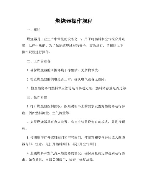
燃烧器操作规程一、概述燃烧器是工业生产中常见的设备之一,用于将燃料和空气混合并点燃,以产生热能。
为了保证燃烧过程的安全、高效进行,请按照以下操作规程进行操作。
二、工作前准备1. 确保燃烧器的周围环境干净整洁,无杂物堆放。
2. 检查燃烧器的供电是否正常,确认电气设备无故障。
3. 检查燃烧器的燃料供应管道是否畅通无阻,燃料储存量是否足够。
三、操作步骤1. 打开燃烧器控制面板,按照说明书上的要求设置好燃烧器运行参数,例如燃料流量、空气流量等。
2. 如果燃烧器具有点火装置,将点火装置设为自动模式,并进行预热。
3. 按照顺序打开燃料阀门和空气阀门,使燃料和空气开始流入燃烧器内部。
注意,先打开燃料阀门,再打开空气阀门。
4. 监测燃料和空气流入燃烧器的情况,确保流量稳定并达到运行要求。
如有异常,立即关闭阀门,检查并修复故障。
5. 预热完成的点火装置将自动进行点火,观察点火情况。
如果点火失败,请立即关闭阀门,检查点火装置并重新调整。
6. 通过观察燃烧器出口的火焰情况来判断燃烧质量。
正常情况下,火焰应该是蓝色而稳定的,如有异常,应立即关闭阀门并检查原因。
7. 在燃烧器运行期间,时刻注意火焰的稳定性和燃料供应的充足性。
如果发现火焰异常或者燃料不足,请及时采取措施解决问题。
8. 当燃烧过程结束或者需要停止燃烧器时,先关闭燃料阀门,再关闭空气阀门。
确保燃料和空气的流入被切断。
9. 关闭燃烧器控制面板,并将设备恢复到停机状态。
四、安全注意事项1. 操作过程中必须穿戴个人防护装备,包括安全帽、耐热手套、防护眼镜等。
2. 操作人员必须熟悉燃烧器的使用说明书,了解其工作原理和操作方法。
3. 严禁在燃烧器周围堆放易燃物品,确保通风良好。
4. 燃烧器操作过程中如有异常情况,应停机处理,并及时向上级报告。
5. 维修和保养燃烧器时,必须切断电源,并在操作前进行安全演练。
五、维护与保养1. 定期检查燃料供应管道和阀门,确保其无漏气现象。
燃烧器说明书(中英文)

二级点火 Two Classes Ignition
角执行机构 Angle Action Device
400Nm,220V,4~20mA 控制电流 Control Current
四、安装与调试 Installation and Regulation 1、燃烧器安装 燃烧器上安装法兰与炉墙上预留的安装法兰用 12 只 M16×50
After regulation, close the box tightly, and protect it from dust.
五、操作步骤 Operation Steps 1、点火 Ignition (1)点火:检查油管路系统,将各手动阀置于开位。启动电动推进器按钮,将
点火枪送至油枪前端。将风油联动系统开度至 40%处,启动高能点火器点火按钮使其 点 火 , 接 着 打 开 燃 烧 器 前 的 点 火 油 枪 进 油 电 动 阀 , 此 时 燃 油 即 开 始 雾 化 燃 烧 。( 高 能 点火装置连续工作时间不能超过 30 秒),火焰稳定后火检着火信号反馈,主油枪进油 电动阀和回油电动阀打开,主油枪燃油雾化燃烧,点火油枪进油阀关闭,火检信号反 馈稳定,点火成功!(油枪前压力保证 2.8~3.5MPa)。 Ignition: check oil pipeline, and open all the manual valves. Press electric actuator start button, and advance spark rod to oil gun front. Open the air and oil regulator to 40%. Press HEA exciter ignition button, and open the oil inlet electric valve of ignition oil gun in front of burner, then the fuel is atomized combusting (the HEA exciter may not work over 30s continuously). The flame on signal is sent from flame scanner when the combustion is stable. Open oil inlet electric valve and oil return electric valve of main oil gun. Oil in the main oil gun is atomized combusting. Close oil inlet valve of ignition oil gun. When signals from flame scanner indicate stable
- 1、下载文档前请自行甄别文档内容的完整性,平台不提供额外的编辑、内容补充、找答案等附加服务。
- 2、"仅部分预览"的文档,不可在线预览部分如存在完整性等问题,可反馈申请退款(可完整预览的文档不适用该条件!)。
- 3、如文档侵犯您的权益,请联系客服反馈,我们会尽快为您处理(人工客服工作时间:9:00-18:30)。
NJ四通道煤粉燃烧器使用说明书南京建安机械制造有限公司目录一、简述 (2)二、产品特点 (3)三、结构简介 (3)四、主要工作原理 (4)五、安装形式 (4)六、运转注意事项 (6)七、操作要点 (7)八、维护与安全 (9)九、常见故障排除 (10)十、售后服务联系方式 (9)一、简述我公司是国内早期专业生产三、四通道喷煤管的厂家之一,与南京水泥设计院长期合作。
八十年代末即制造NC型煤粉燃烧器,我公司生产的喷煤管在煤粉进口处用20CrMnTi 渗碳钢加耐磨陶瓷,头部耐热钢材质为Cr25Ni20Si2。
产品设计合理、技术先进、质量可靠,对煤的适应性强,可燃烟煤、无烟煤等特点。
深受用户欢迎并广泛地运用于国内水泥制造企业。
用户在使用本产品之前请详细阅读本说明书。
二、产品特点1 火焰形状可调性好NJ四通道煤粉燃烧器具有多种调节手段,旋流风通道的轴向移动;旋流、直流风的不同比例及出口喷射流型,可在总风量不变或少变的条件下大范围无级调整,从而可获得能适应任意工况的火焰形状。
2 有关技术参数直流风风速:140—250m/s 压力≥23kpam旋流风风速:110—240m/s 压力≥22kpam煤风风速:20—35m/s3 节能降耗由于一次风量低(5-8%),且直流风和旋流风可调至最佳比例,有利于完全燃烧,因而NJ四通道煤粉燃烧器可有效降低煤耗。
理论和实践表明每减少1%的一次风量约可降低热耗8.37—10.46kJ/kg熟料。
4 可适应低挥发份煤NJ煤粉燃烧器燃烧推力强劲,同时理根据燃烧挥发份(%)适当提高煤粉细度(即0.09mm)筛余百分数控制在挥发份百分数的0.5—0.75倍,燃烧低挥发份煤(包括无烟煤)可获得良好效果。
5低NOx排放量由于NJ四通道煤粉燃烧器头部有一由高温烟气回流形成的负压区,且其火焰消除了局部高温,沿窑长的温度曲线变化平稳,因而可有效抑制“燃料NOx”和“高温NOx”的产生。
NOx的排放量达国家水泥厂环保烟气排放标准。
三、结构简介NJ四通道煤粉燃烧器是跟踪国外先进的燃烧器技术,在消化吸收的基础上,研制开发成功的。
其外形结构如图1所示图1.NJ四通道煤粉燃烧器外形结构图1.喷嘴总成:选用优质耐热钢,对部分部件进行了表面材质处理,提高了硬度和耐磨性能;2.喷煤管前端吊点:能旋转调整3℃;3.直流风压力表:0-0.06MPa;4.旋流风压力表:0-0.06MPa;5.螺旋顶安装位置:配合调整煤管高低;6.旋流风风管调整机构:旋转调整螺母可移动+15/-15mm,以补偿由温度引起的风道长度差,调节火焰旋流强度及火焰形状;7.直流风蝶阀:控制直流风风量及风压;8.旋流风蝶阀:控制旋流风风量及风压;9.中心风蝶阀:控制中心风风量及风压。
10。
点火枪安装处四、工作原理NJ四通道煤粉燃烧器,采用四个通道,喷嘴结构图见图2,由内向外依次为中心风通道、旋流风通道、煤风通道、直流风通道。
中心风主要调节燃烧出口处回流区的位置及大小,同时起保护燃烧器头部的作用;旋流风道采用螺旋叶片的轴流式旋流器,其气动阻力小,旋流强度大,旋流风的高速回旋气流,可产生内部回流区,卷吸窑内高温气体,从而起到稳定燃烧的作用;煤风(煤粉与气体混合物)具有输送煤粉与调节火焰的作用;直流风喷口采用20—40个周向分布的专用喷嘴,喷射高速气流,卷吸二次高温风,确保煤粉与热烟气充分混合,强化燃烧。
剖视图端面图图2.NJ四通道煤粉燃烧器喷嘴结构图五、安装形式1.安装方式1)、吊装行车式2)、地轨小车式3)、根据用户现有的安装条件安装。
图3.吊装行车示意图图4.地轨小车示意图2.定位燃烧器安装定位图见图3,一般燃烧器安装在窑的第Ⅳ象限。
2500T/D以下的窑,一般定位在窑的中心点位置。
3.安装注意事项1)无论何种安装方式,除螺旋顶压力杆外,不得有任何施力件或受力件,搭接在燃烧器本体上,否则会因此受到限制,进而导致头部结构破坏。
如果采用刚性伸缩管作煤风管或净风管,须确保该伸缩管的伸缩所需力度小于燃烧器伸缩节的伸缩力度极限,不得使伸缩节产生拉伸形变。
六、运转注意事项1)对燃烧器设备进行气密性及调节控制系统常规检查。
2)在节流阀完全敞开状况下一次风机试车4小时,记录燃烧器系统中的压力分配。
3)、直流风表压和旋流风表压均能同时达到0.022MPa以上。
4)、在无煤粉的条件下,开启煤风机试车,确保煤风表压能达到0.002MPa。
油枪的油压调整到0.15—0.25MPa。
七、操作要点1.基本操作要点:采用NJ四通道煤粉燃烧器应将窑系统工艺操作同燃烧器操作视为整体,看火工要熟练掌握窑内物料煅烧情况,善于综合分析,前后兼顾,且有预见性,做到“三稳”(稳定操作、稳定热工制度、稳定料量),“三勤”(勤看、勤联系、勤调节),窑速稳中求快。
1)操作准备工作* 回转窑已进入操作状态*检查燃烧器耐火浇注料是否完整无损,不完整不得使用。
* 燃烧器已伸入窑头且已调整定位* 一次风机开启* 煤粉输送系统已清理干净,无煤粉存在,处于准备操作状态* 安全措施具全,检查各压力表读数点火注意事项正常点火:为降低喷爆危险,在点火和驱气期间,应关闭窑尾电收尘高压系统和振打设备,充电系统应接地。
火焰熄灭时应中断燃料供应。
热窑点火:窑衬和物料的温度必须超过800℃,如需要,点火前回转窑必须转过1/4圈以提供新的窑衬热表面和物料。
无把握时可用火把点火。
2)操作点燃油枪:1)启动油泵,压力0.15—0.25MPa;2)用小火把点火。
启动期间:1)送煤量约正常值的1/3—1/5,调节短火焰;2)旋流风和直流风的推荐压力参数为0.01—0.02MPa;3)煤风推荐压力参数为0.002—0.004MPa。
稳定生产期间:1)退出油枪0。
5m左右;2)开启蝶阀调节最佳长火焰,旋流风和直流风的推荐压力参数为0.02—0.025MPa ;3)煤风推荐压力参数为0.008—0.01Mpa。
火焰的形状可用调节各阀和改变各风道的轴向相对位置来改变,也可以通过改变煤粉喷口处速度来调节。
在正常操作过程中,二次风温必须达到800—1000℃,以确保最佳的燃烧状况。
2.燃烧器使用调整的基本原则1)确保燃烧器耐火浇注料的完整性,生产过程中要经常检查耐火浇注料,发生破损后必须停止使用,否则将使燃烧器头部材质严重烧损。
因浇注料破损造成的损害,不属于本产品的质保内容。
2)保持窑内物料填充率、窑速、火焰温度、火焰形状的稳定;3)如窑内温度略偏低,适度增减燃料,主要考虑调节旋流、直流风,改善燃烧条件。
窑温偏高应及时减少燃料;4)调整煤风要及时,但不得猛增、猛减,力求稳定;5)加煤时,应相应增加旋流、直流风量;6)合理调整燃烧器的位置,一般是离料近窑皮厚,离料远窑皮薄,火焰高窑皮短,火焰低窑皮长。
3 煅烧过程中的常见现象及对策现象原因对策11窑内火焰呈白色温度过高减旋流风、增直流风、注意燃料计量,适量减煤。
2 窑内火焰呈黄色温度偏低适当增加旋流风,尽量不增加燃料。
3 物料黑影向窑头移动烧成带温度下降增加燃料增加旋流风降低窑速4 烧成带物料发粘带得很高,熟料结粒较大(50mm以上),窑转动电流上升,出现波动。
窑温偏高减少燃料量减少旋流风增加直流风拉长火焰5 烧成带物料发散,几乎无结粒,物料带得很低,窑转动电流下降,且较稳定。
物料易燃性差,窑温偏低增加燃料量增加旋流风减少直流风强化火焰调整配料方案6 烧成带掉窑皮温度过高、火焰形状不好、热工制度不稳定、燃烧器定位不对减小或关闭旋流风;减少燃料量;增加直流风拉长火焰,改变火点位置,重新校正燃烧器定位;控制热料结粒,使窑皮重新补好。
7 火焰跳动*煤粉量波动*二次风温太低*煤粉管中的输送速度不足*检查供煤系统,确保煤仓卸料的平稳,供煤均匀;*调节配料控制,提高二次风温;*增加煤风速度。
4.关闭燃烧器停止煤粉输送。
1)放空燃料输送系统。
2)燃烧器从窑头罩中退出,在窑未冷却到前500℃,直流风和旋流风(少风量)不得停止。
3)燃烧器全部抽出窑头罩后,冷却风可逐步停止。
5. NJ四通道煤粉燃烧器的基本操作参数(仅供参考)正常操作条件下:煤风道表头压力为0.004—0.01MPa旋流风道表头压力0.02—0.030MPa,直流风道表头压力0.02—0.030MPa,中心风道表头压力0.001—0.002MPa。
八、维护与安全1.维护查工作内容消除失误可能采取的措施检查风管内有无杂物消除杂物检查燃烧器轴向的严密性修理或密封检查燃烧器风管有无磨损依据剥落程度,进行修复检查油燃烧器清理燃烧器喷嘴(不得损坏喷嘴孔)检查内煤粉喷嘴的磨损情况及耐火浇注料包套的完整性依磨损程度,以表面耐磨堆焊方式修理检查喷射嘴是否堵塞清理已堵塞的喷射嘴检查压力表联接管路有无沉积清理联接管路检查煤粉输送管的弯管的磨损情况修理损坏部位2.安全技术要求1)为了避免带电,所有煤粉输送设备和输送管路都应接地;2)供煤及计量系统运行中应保持稳定、可调,特殊情况下可以及时中断;3)操作运行中注意检查巡视,以避免由输送管道堵塞、密封失效造成煤粉外漏引起爆炸等不必要事故;4)建议煤粉进入输送泵前增加杂质分离设备。
九、常见故障排除故障原因处理措施1 压力表失灵*煤粉湿度过大*杂物堵塞*检查煤粉湿度,清理杂物2 蝶阀失灵*杂物堵塞*密封橡胶损坏*检查蝶阀,清理杂物。
*更换蝶阀。
3 煤粉通道堵塞*杂物堵塞*停机时煤粉受潮沉淀结块*清理杂物。
*注意停机时的操作。
4 火焰在一侧局部燃烧*在煤粉风管出口处有杂质*煤粉管的支承筋板损坏*去除杂质*检查环形煤粉喷嘴是否对中分布十、售后服务联系方式用户使用本燃烧器产品,如发现自己不能解决的问题,可通过电话、传真、信函通知我们,我们将及时派出工程技术人员上门服务。
联系人:周凤鸣 138********联系电话:025-******** 57907002传真:025-********南京建安机械制造有限公司10。