燃烧器说明书(中英文)
威索WG LN燃烧器中文说明书

83048952 – 2/99C安装使用说明书 威索燃气燃烧器WG30.../1-C, ZM-LN (低NO X )结构 WG40.../1-A, ZM-LN (低NO X )结构- weishaupt -外壳接线插头燃烧器管理器燃烧器马达点火装置风门调节螺钉混合室外壳燃气蝶阀伺服马达马达电容器风压开关连接法兰燃烧头混合室离子电极分配星稳焰盘稳压阀球阀气压开关双重电磁阀DMV燃气过滤器液晶显示屏燃烧器法兰风门伺服马达点火电极2目录1 一般说明 32 安全说明 43 技术说明 6 3.1 使用注意事项 6 3.2 功能 6 3.3 操作面板 74 安装 8 4.1 安装安全注意事项 8 4.2 供货、运输、仓储 8 4.3 安装前的准备 8 4.4 燃烧器的安装 9 4.5 燃气阀组的安装 10 4.6 燃气阀组的气密性检验 12 4.7 电气连接 135 调试与操作 14 5.1 首次调试时的安全指示 14 5.2 在首次调试前的措施 14 5.3 首次调试 15 5.4 功能流程接线图 25 5.5 显示及操作面板 27 5.6 停机 286 故障原因及排除 297 保养 32 7.1 保养工作的安全说明 32 7.2 保养计划 32 7.3 混合室的拆卸与安装 33 7.4 混合室的调节 33 7.5 点火电极的设定 34 7.6 罩盖的保养位置 34 7.7 叶轮及燃烧器马达的拆卸与安装 35 7.8 风门伺服马达的拆卸与安装 35 7.9 风门传动机构的拆卸与安装 36 7.10 燃气蝶阀伺服马达的拆卸与安装 36 7.11 DMV 上电磁体的拆卸与安装 37 7.12 稳压阀内弹簧的拆卸与安装 37 7.13 燃气过滤器内部滤芯的拆卸与安装 38 7.14 燃烧管理器的拆卸与安装 388 技术数据 39 8.1 燃烧器配置 39 8.2 工作范围表 39 8.3 允许使用燃料 40 8.4 电气数据 40 8.5 允许的环境条件 40 8.6 尺寸 40 8.7 重量 41附录燃气流量的计算 42 燃烧值的检验43本安装使用说明书¾是燃烧器供货时同时提供的,在使用地点应能随时找到¾应由专业人员进行解释¾包含了燃烧器安装、调试及保养安全性方面的重要说明¾所有与燃烧器操作有关的人员都应加以注意移交及操作说明热能装置的供应方应最迟于移交设备时向接收方提供操作指导,并澄清该操作指导应保留在设备使用地点。
百得BGN-100P燃烧器中文说明书

IEC 730-1 (VDE 0631 T1)
(12) (4)
P1 L1
Mp N
P2 L2 V1,V2 V2
16
筑
DUNGS (GASMULTIBLOC) MB-ZRDLE 415 B01 S22 (1"1/2) / MB-ZR)
MB-ZRDLE B01 ...S.. a) b) c) d) e) ( ( (8) ( ) (7) ) ) (9) (6) DUNGS (10) 5 - 120 mbar
N° 7604-2 Rev. 02/02/96
ul
on g.
co
m
L.P.G.
ww w.
zh
BGN 120 P - 350 P
N° 7605-5 Rev. 17/11/97
筑
龙
网
L.P.G.
5
(
400 mm
) (
8780.tif
400 mm
= 0,04 kg/cm2)
1) 1.5 - 2 2)
3)
MB ..... MB...
DUNGS DUNGS
(400mm
)
BT 8871
网
ww w.
zh
ul
on g.
co
m
筑
龙
DUNGS
6
N° 8871
(
)
BGN 40 P - 250 P
0002933330
1234-
(
)
ww w.
BGN 300 P - 350 P
zh
123450002933340
筑
龙
网
1,2,3,4,5,
on g.
ul
Carlin CRD 油燃烧器说明书
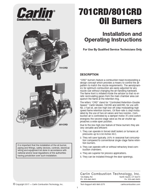
701CRD801CRD It is important that the installation of the oil burner, piping and fittings, safety devices, controls, electrical wiring and equipment be done in accordance with national and/or local regulations of the authorities having jurisdiction over such installation.Copyright 2017 — Carlin Combustion Technology, Inc.2LOW-HIGH-LOW (STEP-MODULATION) FIRINGAdvantages: There are several strong advantages to low-high-low firing in both heating and process applications:1. Smooth ignition both in natural and forced draft opera-tions.2. Closer control than with a single input.3. L ess strain or wear on the burner, boiler and combustion chamber components: a. Longer cycles.b. Gradual changes; less thermal shock.4. L ower fuel consumption:a. Higher efficiencies of both low and high fire.b. L ower stand-by loss due to longer ON cycles and to the closed air damper during OFF cycles.Operation: A true low-high-low burner controls both air and oil flow rates. A low fire start burner (low-high-off) con-trols only the oil rate and has a fixed air setting with none of the advantages of 1, 2, 3, or 4 above. The low-high-low burner cycle operates as follows:1. C all for heat. Burner motor and ignition are energized. Air is in the low fire position. The low fire oil valve admits oil to the low fire nozzle and its spray ignites, burning clean with proper air/fuel ratio.2. I f demand exceeds low fire, the damper motor is en-ergized through a high fire operating control (aquastat, airstat, pressure-trol, or outdoor thermostat.) As the damper motor approaches a wide open position, the auxiliary end switch energizes the high fire valve and the full fire with open air. Burns clean with high CO 2 and high efficiency.3. A s the high fire input begins to exceed the demand of the high fire operator, the operating control opens to de-energize the damper motor. As the damper motor returns the air shutter to low fire the auxiliary end switch in the damper motor opens and de-energizes the high fire valve.4. I f the demand exceeds low fire, the high fire operating control would again call for more heat as in Step 2 and then followed by Step 3.5. I f, after returning to low fire, the load should drop tobelow the low fire output, the operating limit would shutoff the burner completely.ASSEMBLING THE BURNER (TWO-PAK)1. R emove the air tube and nozzle line assembly from the smaller carton. If nozzles are not installed, see instruc-tions under (4).2. R emove the main housing assembly from the larger carton.3. I nstall air tube assembly in housing using set screws provided. Be sure air tube is fully seated against step in housing4. I nstall and tighten the proper nozzles (see Tables 5 & 6. page 4) in the adapter. Be careful not to damage the electrode insulators or to bend the wires.5. Check the electrode settings.FIG. 16. S wing open the transformer and slide the nozzle line assembly into the air tube. On Model 801CRD, the flame retention ring must be lifted and guided through the throttle ring (a reduced diameter) in the end of the airtube. DO NOT FORCE IT.7. F asten the high tension leads to the transformer termi-nals.8. P lace the nozzle line yoke in the groove in the adjustingscrew. 9. Swing the transformer to the closed position.10. C onnect the flared fitting on the copper oil lines to thenozzle lines and tighten.11. S ee sections on page 4 for adjustments of combustionhead and combustion air.DIMENSIONSMODEL STD.FLANGE B.C.FORCED DRAFT FLANGEB.C.O.D.701CRD 596426⁄-7⁄594449-10"11"801CRD596836⁄-7⁄5953510"11"MODEL A B C D 1D 2E F L W X 701CRD 7⁄9⁄104⁄5⁄13910⁄-14⁄19⁄2⁄801CRD812115⁄5⁄14⁄10⁄10-152333TABLE 1 701CRDMINIMUM DIMENSIONS RECOMMENDED IN REFRACTORYCOMBUSTION CHAMBERS–(Inches)1High Fire Oil Delivery Rate GPH @150 PSI 2Length L 3Width W 4Dimens.C 5Suggested Height H 6Minimum Dia.Vertical Cyl.6.006.607.207.808.409.009.6010.2010.8011.4012.0012.6013.201922242730333435363748525513.514.014.515.015.515.516.016.016.016.516.516.516.57.07.07.57.58.08.08.08.08.08.58.58.58.51314141515151616161616161617202425283132333435465053Note: These are MINIMUM dimensions and each may be exceeded without much effect.TABLE 2 801CRDMINIMUM DIMENSIONS RECOMMENDED IN REFRACTORYCOMBUSTION CHAMBERS–(Inches)1High Fire Oil Delivery Rate GPH @150 PSI 2Length L 3Width W 4Dimens.C 5Suggested Height H 6Minimum Dia.Vertical Cyl.11.412.012.613.213.214.415.015.616.216.817.418.018.619.219.83334353638394041434446474951521516161717181819192020212122227.58.08.08.58.59.09.09.59.510.010.010.510.511.011.0151616171718181919202021212222313233343637383941424445474950Note: These are MINIMUM dimensions and each may be exceeded without much effect.Refer to Fig. 2 for details showing L, C & H.TABLE 3 701CRDMINIMUM DIMENSIONS RECOMMENDED BOILERS FIREDWITHOUT COMBUSTION CHAMBERS–(Inches)1High Fire Oil Delivery Rate GPH @150 PSI 2L With Target 3L Withou Target 4Width W 5Dimens.C 6Dimens.D 6.006.607.207.808.409.009.6010.2010.8011.4012.0012.6013.20192224273033343536374852552326283235384041424354586015.516.016.517.017.517.518.018.018.018.518.518.516.58.08.08.58.59.09.09.09.09.09.59.59.59.510.010.010.510.511.011.011.011.011.011.511.511.511.5TABLE 4 801CRDMINIMUM DIMENSIONS RECOMMENDED BOILERS FIREDWITHOUT COMBUSTION CHAMBERS–(Inches)1High Fire Oil Delivery Rate GPH @150 PSI 2L With Target 3L Withou Target 4Width W 5Dimens.C 6Dimens.D 11.412.012.613.213.814.415.015.616.216.817.418.018.619.219.83334353638394041434446474951523839404143444647495052545658591718181919202021212222232324247.58.08.08.58.59.09.09.59.510.010.010.510.511.011.09.510.010.010.510.511.011.011.511.512.012.012.512.513.013.0Refer to Figs. 3 and 4 for details showing L, C & DFIRING BOILERS WITHOUT REFRACTORY CHAMBERSDepending upon the geometry of the combustion space some units perform better than others without refractory. When the back wall of the unit coincides approximately with the end ofthe flame, a target of refractory material is usually required.Tables 3 and 4 show MINIMUM dimensions required for good combustion. They may be exceeded without much effect.FIRING BOILERS WITH COMBUSTION CHAMBERSThe Models 701CRD and 801CRD operate with superior efficiency and cleanliness in properly designed refractory-type combustion chambers. Very wide tolerance to burner adjustments and other variables is found when these chambers are used.Tables 1 and 2, show the recommended minimum inside dimensions for refractory brick, refractory pre-cast andpre-formed refractory fiber chambers. Due to their quick warm-up properties, the light, insulating-type materials are slightly preferable although these burners show less dependence upon refractory temperature than previous models. Refractory materials in boilers and furnaces should be capable of withstanding 2600°F (1427°C) or higher.The notes accompanying Table 1 and 2 provide further details relative to variations in dimensions and geometry.4INSTALLING THE BURNER: FLANGE MOUNTED1. M easure, in the burner opening, the distance from theinside of the combustion chamber to the outside of themounting plate to find the insertion length of air tubeneeded. Position flange with sleeve inside on air tubeat a point from end of burner corresponding to thismeasurement. Tighten set screws to anchor flange. Theflange is now located so that the end of the burner willbe flush, or almost flush, with the inside of the combus-tion chamber.2. S lide the end of the air tube into the opening and securethe flange to the front plate.FIG. 2Brick combustion chamber, side view.FIG. 3Wet leg boiler. No combustion chamber, side view.FIG. 4Scotch Marine boiler. No combustion chamber.INSTALLING THE BURNER: PEDESTAL MOUNTED1. A djust the pedestal so that the height of the air tubematches the location of the burner opening.2. S lide the end of the air tube into the opening so that it isflush or nearly flush with the inside ofthe combustion cham-ber.3. F rom the outside of the unit, seal the space around the airtube with refractory cement or equivalent.FIG. 5 FIG. 6HOW TO ADJUST THE COMBUSTION HEADThe retention ring position ahead of the throttle ring isadjustable from zero (flush) to 11⁄4 inches (Dimension “A”Figs. 7 and 8). Turning the adjusting screw in (clockwise)increases the distance “A“ ahead. This distance is indi-cated by lifting the housing cover and reading the scale onthe nozzle line across the corners on sides of the channelguiding the nozzle line. Each division is 1⁄16 inch.Refer to “A” dimension given in Table 5 and 6 for cor-responding nozzle selection. (If alternate nozzle sizes areused select “A” dimension from the high fire oil deliveryrate. Column 5). EXAMPLE: 70lCRD firing at 11.40 GPHhigh fire. “A” column setting reads 1⁄4".1. T urn adjusting screw counterclockwise until zero onscale is aligned with rear of housing (“A” equals zero seeFig. 8).2. N ow turn adjusting screw clockwise until the ‘/J’ gradu-ation on the scale coincides with rear of housing. Eachmark (or line) is 1⁄16 inch. (See Fig. 8).3. T he retention ring will now be exactly 1⁄4" ahead of thethrottle ring. (See “A” dimension. Fig. 7).CAUTION: Housing coxer should be raised slightly whenattempting to change retention ring setting (“A” dimension)otherwise scale will be torn or distorted. This can be doneby backing out the two hold-down screws 2 to 3 turns. andthen lifting cover slightly while adjusting. Be sure to tightenscrews after adjusting.FIG. 7 FIG. 8COMBUSTION HEAD ADJUSTMENT FORCOMBUSTION AIRWhen adjusting the combustion head forward or back, thespace around the rim ofthe retention ring is increased ordecreased which increases or decreases the amount ofcombustion air to correspond with the nozzle sizes used.Also, by using the specified nozzle combinations for lowand high fire (Tables 5 and 6), the air fuel ratio for bothlow and high fire are optimized by the automatic dampermotor and its associated linkage. THIS LINKAGE HASBEEN PRE-SET AT THE FACTORY AND SHOULD NOT BEADJUSTED. It is set to be in the fully open position whenthe burner is in high fire.By adjusting the combustion head according to Tables 5and 6 (last column), for the firing rate delivered by the par-ticular nozzles, the burner should deliver very close to theproper amount of combustion air and CO2. Slight increasesor decreases will usually be required depending upon thedraft. Normally a draft of 0.02 to 0.04 inches W.C. (nega-tive pressure) is recommended over the fire for natural draftapplications.Model 701CRD is provided with a low fire air shutter ad-justing screw. This adjustment limits the amount of shutterclosure which thereby increases or decreases the amount of combustion air required for proper burning.Model 801CRD is supplied with separate low fire and high fire air shutters. The low fire air shutter has an adjusting screw which should be adjusted to get a clean, low fire. The high fire air shutter is not adjustable and moves with the linkage that is preset at the factory.* W hen field conditions are unusual or if the load requires it, the low fire and high fire may be altered such that the low fire is increased and the high fire de-creased as needed. The low lire air shutter adjusting screw will require turning to the revised nozzle sizes.*"A"–See Figs. 7 and 8, Page 4.NOZZLE SPECIFICATIONSThe nozzles shown in Tables 5 and 6 are standard and usually provide the best fire. Substitutions are not normally recommended.Other makes of nozzles may or may not prove satisfactory. For special applications. other specifications might provide a more desirable pattern.FORCED DRAFT FIRINGDue to the back pressure in forced draft units the maxi-mum firing rate of a burner is reduced. The greater the pressure, the lower the maximum GPH capability becomes. Table 7 shows this. Note that the Table stops at 0.50 inches W.C.: the maximum recommended back pressure for these models.The combustion head settings for forced draft firing would be somewhat greater than those shown in Tables 5 and 6 which are for zero pressure or natural draft.FUEL UNITS AND OIL LINESStandard burners are provided with a two-stage 3450 rpm fuel unit set at 150 PSI.A single-pipe system is recommended whenever the bot-tom of the fuel tank is above the burner or is at the same level as the burner. This includes outdoor fuel tanks that are at such levels. The length of run should not exceed 100 ft. and the vacuum should not exceed 12" mercury (5.9 PSI). Be sure the by-pass plug has been removed for single-pipe systems.A two-pipe system is recommended when the fuel tank is below the level of the burner and the fuel unit must pull (lift) the fuel up to the burner. The vacuum reading should not exceed 12" mercury (5.9 PSI). For two-pipe installations the by-pass plug must be installed.Table 8 shows, for the standard two-stage fuel unit, the al-lowable lift and lengths of 1/2" and 5/8" OD tubing for both suction and return lines in two-pipe systems.TABLE 5 701CRDNOZZLE DATA AND COMBUSTION HEAD SETTINGSNozzle Specifications Hago Products Corp.Oil Delivery RateGPH @ 150 PSI“A”*ApproximateRetentionRing SettingOn ScaleLow FireAirShutter1st Stage2nd Stage Spray Low Fire High Fire3.00 2.0060°H 3.60 6.001/16"1/8"3.25 2.2560°H 3.90 6.603/16"1/8"3.25 2.7560°H 3.907.201/4"1/8"3.50 3.0060°H4.207.805/16"1/4"3.50 3.5060°H4.208.403/8"1/4"3.75 3.7560°H4.509.007/16"3/8"4.00 4.0080°H 4.809.601/2"1/2"4.00 4.5060°H 4.8010.209/16"1/2"4.50 4.5060°H5.4010.805/8"5/8"4.505.0060°H 5.4011.403/4"3/8"5.00 5.0045°H6.0012.007/8"3/4"5.00 5.5045°H6.0012.6011⁄16"3/4"5.006.0045°H 6.0013.2011⁄4"3/4"TABLE 6 801CRDNOZZLE DATA AND COMBUSTION HEAD SETTINGSNozzle Specifications Hago Products Corp.Oil Delivery RateGPH @ 150 PSI“A”*ApproximateRetentionRing SettingOn ScaleLow FireAirShutter1st Stage2nd Stage Low Fire High Fire5.50 4.006.6011.401/16"1/4"5.50 4.506.6012.001/16"1/4"5.50 5.006.6012.601/48"1/4"5.50 5.506.6013.203/16"1/4"6.00 5.507.2013.801/4"3/8"6.00 6.007.2014.405/16"3/8"6.00 6.507.2015.003/8"3/8"6.50 6.507.8015.607/16"1/2"6.507.007.8016.201/2"1/2"6.507.507.8016.803/8"1/2"6.508.007.8017.403/4"1/2"6.508.507.8018.007/8"1/2"7.008.508.4018.601"5/8"7.009.008.4019.2011⁄8"5/8"7.009.508.4019.8011⁄4"5/8"TABLE 7MAXIMUM FIRING RATES (GPH)–FORCED DRAFT BurnerModelCombustion Chamber Pressure0.000.100.200.300.400.50INS.W.C.701CRD13.2012.7012.3011.8011.3010.90801CRD19.8019.4019.0018.6018.2017.80TABLE 8MODEL 701CRD & MODEL 801CRDTWO-STAGE UNITS–TWO-PIPE SYSTEMS (150 PSI)Length of Tubing (feet)Lift (feet)1/2" OD5/8" OD2468101214151008878695949392924100100100100100100100826856Be sure that all oil line connections are absolutely air tight. Check all connections and joints. Flared fittings are required. Do not use compression fittings.Open the air-bleed valve and start the burner. For clean bleed. slip a 1/16"" ID hose over the end of the bleed valve and bleed into a container. Continue to bleed for 15 seconds after oil is free of air bubbles. Stop the burner and close the bleed valve.LIGHT -OFF AND ADJUSTMENTNOTE: W HEN STARTING THIS BURNER THE FIRST TIMEOR AFTER CHANGING NOZZLES, THE FLAME MAY GO OUT DURING THE SWING FROM LOW TO HIGH. BE READY TO SHUT THE BURNER DOWN JUST AFTER THE FLAME GOES OUT.REPEAT THIS UNTIL THE AIR IS PURGED OUT OF THE HIGH FIRE OIL LINE.Before starting the burner, pre-set the retention ring posi-tion for the particular firing rate according to Table 5 for the 701CRD or Table 6 forthe 8O1CRD.If the fire is a little too rich, move the combustion head forward by increasing dimension "A" (Fig. 7 and 8). At the lower inputs, a very slight change is usually enough. DO NOT ALTER THE LINKAGE. IT IS PRE-SET AT THE FAC-TORY .Model 701CRD is provided with a low fire air shutter ad-justing screw. This adjusting limits the amount of shutter closure which thereby increases or decreases the amount of combustion air required for proper burning.Model 801CRD is supplied with separate low fire and high fire air shutters. The low fire air shutter has an adjusting screw which should be adjusted to get a cIean, low fire. The high fire air shutter is not adjustable and moves with the linkage that is pre-set at the factory.Adjust draft to 0.02 to 0.04 inches W.C. over the fire for natural draft units.Run a smoke test. Strive for zero or a trace. Each time further adjustment of retention ring is made, reset the draft to 0.02 to 0.04 inches W.C. over the fire.Check CO 2. This should be 12 to 121⁄2 percent, and will often be over 13 percent, in a welI-sealed unit.Check for good ignition and clean cut-off. If cut-off con-tinues to be poor, look for air leaks in the suction line and correct them.For different boiler applications, it is sometimes necessary to have the high-fire pull in earlier or later than normal dur-ing the swing to achieve a smooth, cleaner transition.If the swing from low-fire to high-fire is rough, i.e. bangs or rumbles or is extremely smoky, the internal end switch of the damper motor is possibly not set correctly. The high-fire should pull in as the air shutter, NOT THE DAMPER ARM, is about half way through its swing.If the fire is lean all the way to high-fire, the high-fire valve should be energized earlier. lf during the swing, the fire gets very smoky, then cleans up again, the high-fire valve should be energized later.To adjust the damper end switch, remove the damper motor cover. This will expose a white plastic gear withnotches. With the burner off, use the end of a small bladedscrewdriver inserted into one of the notches of the white gear. Turn the gear one notch clockwise if a later pull-in is required, or counter clockwise for an earlier pull-in.The linkage between the damper motor arm and the air shutter crank is set at the factory and should only need adjustment if the damper motor or damper rod is replaced. With the burner in high-fire. there should be minimal play in the connecting rod.WIRING FOR LOW-HIGH-LOW STEP MODULATIONIn order to take full advantage of the energy savings poten-tial of these bumers they should be wired to operate with low-high-low cycles. Hence the firing cycle would be much longer by going from low to high to low once or several times before shutting off.In the following illustrations are two examples: 1. Water Boiler. 2. Steam Boiler. ln each case, we have a limit circuit which starts and stops the burner and a high fire control which brings the high fire on and off.Also, prewired and built into the burner is a manual high fire switch which enables the installer or operator to hold the burner on low fire if so desired.Refer to the appropriate example for your installation.Example: Water Boiler Operating Range 170°-190°F2. Set Safety Hi Limit: Cut in 200 / Cut out 21O3. Set Operating Limit: Cut in 180 / Cut out 1904. Set Hi Fire Control: Cut in 170 / Cut out 180Operation:1. C all for heat: cold start. Burner starts on low and goes to high fire.2. W hen the temperature rises to 130°F , the burner goes to low fire.3. If temperature drops to 170°, burner returns to high fire.4. If temperature rises to 190°, burner shuts off.NOTE: Since the calibrations on the limit controls are seldom exact, it will be necessary to readjust the settings during operation.7Example: Steam Boiler Operating Range 3 to 6 PS12. Set Safety Hi Limit: Cut in 8 PSl / Cut out I0 PSI3. Set Operating Limit: Cut in 8 PSl / Cut out 6 PSI4. Set Hi Fire Control: Cut in 3 PSl / Cut out 4 PSI Operation:1. C all for heat: cold start. Bunier starts on low and goes to high fire.2. W hen pressure rises to 4 PSI, the burner goes to low fire.3. lf pressure drops to 3 PSl burner returns to high fire.4. If pressure rises to 6 PS1 burner shuts off.NOTE: Since the calibrations on the limit controls are seldom exact, it will be necessary to readjust the settings during operation.8MN0000 050317© Copyright 2015 — Carlin Combustion Technology, Inc.T E C H S U P P O R T H O T L I N E 800-989-2275Carlin Combustion Technology, Inc.126 Bailey Road North Haven, CT 06473 Phone 203–680–9401 Fax 203–764–1714e-mail us at: info@ visit our website: 。
利雅路燃烧器中文说明书
利雅路燃烧器中文说明书利雅路(Leverage)是一家专业生产户外用品的品牌,其燃烧器系列备受户外爱好者青睐。
在这里,我们为您详细介绍利雅路燃烧器的中文说明书,让您在使用中更加得心应手。
一、燃烧器的分类及用途燃烧器分为两种:火焰燃烧器和气体燃烧器。
火焰燃烧器适用于烧烤、点燃固体燃料等场景;而气体燃烧器则可以通过连接燃气罐使用,适用于露营、旅行等多种户外活动。
二、燃烧器的组件及操作方法1、组件利雅路燃烧器包含以下组件:火焰喷嘴、温度调节旋钮、火焰开关、点火器、燃气罐地支、燃气连接阀、燃气管路等。
2、操作方法①点火:打开燃气连接阀,按下点火器按钮,即可点燃燃气。
注意:在点燃之前确保燃气连接阀已经严密关闭好,以免发生危险。
②调节火力:利用温度调节旋钮可自由调节火焰大小,根据不同的需求进行调节。
③关闭:当使用完毕后,先关闭燃气连接阀,等待所有部件冷却后再收起即可。
三、维修及保养1、维修燃烧器为高温设备,维修时应当特别小心,以免造成危险。
若发生燃气漏气、火焰不稳定等情况,应及时停止使用,并按以下方法修理:①燃气漏气:立刻关掉燃气连接阀并打开燃烧器,让残留的燃气全部消失,确认消失后再进行修理。
②火焰不稳定:可能是火焰喷嘴堵塞或者燃气罐压力不足等原因导致,可以将火焰喷嘴拆下来清理或者更换新的燃气罐。
2、保养燃烧器的保养很简单,每次使用后清洗一下,移除灰尘和污垢即可。
使用过程中要注意防止火烧坏焦炭,影响燃烧效果。
四、购买及保修1、购买利雅路燃烧器可以在专业户外用品商店购买,根据不同的需求选择不同型号的燃烧器。
2、保修利雅路为燃烧器提供2年免费保修服务,若在保修期内发现燃烧器存在质量问题,可前往销售点或利雅路售后维修中心进行保修处理。
总结通过以上介绍,相信大家已经对利雅路燃烧器有了更加深入的了解。
在使用过程中,务必要注意安全,严格遵守使用说明,以免造成伤害。
在户外活动中,利雅路燃烧器为您提供舒适的烧烤体验和热饮服务,快来选购一款适合自己的利雅路燃烧器,享受美好的户外时光吧!。
威索燃烧器中文说明书
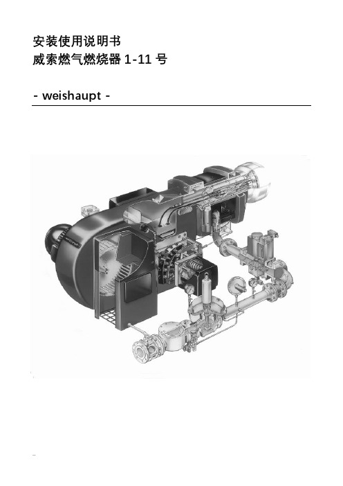
安装使用说明书威索燃气燃烧器1-11号- weishaupt -证明在此我们说明,威索(-weishaupt-)燃气燃烧器符合下列EC标准的基本要求:90/396/EEC Gas Equipment Guideline89/336/EWG Electromagnetic Compatibility73/23/EEC Low Voltage Guideline因此燃烧器上带有CE/0085标记。
其它质量保证体系由DIN EN ISO 9001认可。
德国麦克斯·威索有限公司目录1. 一般说明 (2)2. 燃烧器的安装 (5)3. 气路示意图 (7)4. 阀门组件说明 (8)5. 阀门组件的安装 (16)6. 阀门组件的气密性检验 (19)7. 功能流程检验 (19)8. 准备第一次调试 (20)9.调试 (20)10.燃烧筒及稳焰盘的调整 (32)11. 工作范围表 (33)12. 设置点火电极 (36)13. 鼓风轮的固定 (36)14.工作流程 (37)15. 限制及辅助开关的凸轮位置设置 (44)16. 燃气流量的计算,从标准状态到实际状态的换算 (46)17. 常见故障及排除方法 (48)1. 一般说明简介下表为安装及调试中各个步骤的基本概括为了达到正确安装及调试的目的,请对此说明书中的所有说明加以注意。
步骤工作章节1 燃烧器的安装 22 安装燃气阀门组 53 燃气阀门组的气密性检验 64 检查燃气供气压力8.15 排去燃气阀门组中的空气8.26 功能流程检验77 检查燃烧头108 检查设备9.19 调试9.3 安全性要确保燃烧器的安全运行,必须由合格的专业人员按此说明书进行正确的安装及调试。
要特别注意相关的安全规定(如DIN-VDE,DIN-DVGW)。
火焰监测装置、限制装置,调节机构以及其它安全装置只能由制造厂或其委托单位进行安装。
不遵守规定可能导致人员伤亡及重大物质损失等严重后果。
燃烧器说明书(中英文)

二级点火 Two Classes Ignition
角执行机构 Angle Action Device
400Nm,220V,4~20mA 控制电流 Control Current
四、安装与调试 Installation and Regulation 1、燃烧器安装 燃烧器上安装法兰与炉墙上预留的安装法兰用 12 只 M16×50
After regulation, close the box tightly, and protect it from dust.
五、操作步骤 Operation Steps 1、点火 Ignition (1)点火:检查油管路系统,将各手动阀置于开位。启动电动推进器按钮,将
点火枪送至油枪前端。将风油联动系统开度至 40%处,启动高能点火器点火按钮使其 点 火 , 接 着 打 开 燃 烧 器 前 的 点 火 油 枪 进 油 电 动 阀 , 此 时 燃 油 即 开 始 雾 化 燃 烧 。( 高 能 点火装置连续工作时间不能超过 30 秒),火焰稳定后火检着火信号反馈,主油枪进油 电动阀和回油电动阀打开,主油枪燃油雾化燃烧,点火油枪进油阀关闭,火检信号反 馈稳定,点火成功!(油枪前压力保证 2.8~3.5MPa)。 Ignition: check oil pipeline, and open all the manual valves. Press electric actuator start button, and advance spark rod to oil gun front. Open the air and oil regulator to 40%. Press HEA exciter ignition button, and open the oil inlet electric valve of ignition oil gun in front of burner, then the fuel is atomized combusting (the HEA exciter may not work over 30s continuously). The flame on signal is sent from flame scanner when the combustion is stable. Open oil inlet electric valve and oil return electric valve of main oil gun. Oil in the main oil gun is atomized combusting. Close oil inlet valve of ignition oil gun. When signals from flame scanner indicate stable
燃烧器说明书(新)
FRQ-2DF双燃料燃烧器说明书徐州福尼燃烧控制研究院有限公司二○一○年十月前言_____________________________________________________________________注意感谢您使用徐州福尼燃烧控制研究院有限公司生产的FRQ-2DF型燃烧器。
本手册作为产品完整而必要的一部分提供给用户。
本手册所述内容不仅适用于用户,也可为产品的安装和检修人员提供参考。
关于设备的安装、操作和维护的详细信息,我们建议您仔细阅读。
请妥善保存本手册,以备参考。
_____________________________________________________________________内容介绍:本手册介绍了FRQ-2DF型双燃料燃烧器的结构、特点、安装、操作、维护以及故障处理。
读者对象:本手册适合下列人员阅读:设备安装人员、操作人员、维护人员等。
一、用途及特点FRQ-2DF型系列双燃料燃烧器是徐州福尼燃烧控制研究院有限公司设计开发的节能燃烧设备,它可在工业锅炉、电站锅炉及其它工业窑炉中广泛应用。
FRQ-2DF型双燃料燃烧器能实现助燃风与燃料按比例调节,使燃烧更为稳定可靠,实现全自动运行。
它具有结构紧凑、燃烧稳定、调节比大、噪音低、可内设点火枪和火焰检测报警系统;火焰铺展性好、燃烧完全、燃烧易于控制等特点。
二、主要性能及技术参数1.燃烧器功率:18.5MW/台2.燃烧器调节比:5:13.燃料油参数:油压(枪前油压):1.0~1.2Mpa油枪出力:每台燃烧器1450kg/h雾化方式:蒸汽雾化4.雾化吹扫蒸汽:雾化蒸汽设计流量:300Kg/h雾化蒸汽设计压力(燃烧器前表压):1.0MPa5.燃料气(干气):燃气流量:每台燃烧器2000 Nm3/h燃气气压力(进阀组前):25Kpa燃气温度:常温6.助燃风助燃风温度:常温助燃风压:3500~4500Pa助燃风量:~20000Nm3/h7.点火燃气;点火燃气:干气点火燃气压力:10KPa点火燃气流量:100Nm3/h三、燃烧器及主要配置介绍1.燃烧器燃烧器为双燃料型燃烧器,主要由燃烧器本体、配风器、稳焰装置、燃油喷枪、燃油火检、燃气火检、主气嘴、点火长明灯等组成。
燃烧器说明书(中文)
1.2.5.燃烧空气控制板 燃烧器前面的空气口内装有一个风量控制挡板,它用于调节燃烧器的空气量。 总负荷分十个比例调节位置段,对应调节供风量,每段的斜率可调,使燃烧器处 于最佳状态。
1.2.6.火焰探测装置 燃烧器的主火焰由主火焰探测器来监测。 火焰探测器的连接管安装在燃烧器前板 上,它带有一个冷却空气接头。冷却空气可保持火焰探测器清洁并防止过热。 引导火焰由点火枪的电离杆探测。 1.2.7.观察孔 火焰和燃烧孔通过观察孔来观察。冷却空气流可防止观察孔过热和变脏。
注意: 这些操作和维修指导包括燃烧器制造商的一些资料,可通过使用单位的指导进行补充。 此燃烧器指导说明书,并不包括使用单位特定的工艺流程上的操作与维护的特殊资料,这 些资料需由使用单位制定。 这些特殊工艺的操作与维护资料优先于燃烧器的说明。
1.结构说明
1.1.交付说明
油气燃烧器 GKT-35S 墙式安装在锅炉上。 5 台油气燃烧器 Oilon GKT-35S 制造号:7083 , 7084 , 7085 , 7086 , 7087
当燃烧气体和空气的预混合物在喷嘴内经点火电极点燃时,燃烧产生。 警告:点火电压为 5000V 来自供给管路的液化气和燃烧空气按所需量通过阀装置进入点火枪。 点火枪供有连续的冷却空气流(见操作指导:冷却空气) 点火枪上装有一个机械限位器以保证燃烧器有正确的安装深度。 限位器用六角螺 钉固定在点火枪的框管上,正确安装深度(L1)测量值已记录在“设定值”一章 的表中。
目录
1. 结构说明……………………………………………………………………………………….1.1 1.1.交付范围………………………………………………………………………………1.1 1.2.GKT-35S 燃烧器……………………………………………………….……………1.1 1.3.阀组……………………………………………………………………………………1.4 1.4.自动控制………………………………………………………………………………1.4 2.技术数据……………………………………………………………………………………...2.1 3.操作指导………………………………………………………………………………………3.1 3.1.总述……………………………………………………………………………………3.1 3.2.装配检验………………………………………………………………………………3.1 3.3.第一次启动/长期关闭后的启动的准备工作…………………………………………3.2 3.4.正常运行……………………………………………………………………………….3.2 3.5.启动…………………………………………………………………………………….3.3 3.6.停止和紧急停止……………………………………………………………………….3.3 3.7.油调节装置…………………………………………………………………………….3.4 3.8. 冷却空气………………………………………………………………………………3.10 3.9. 燃烧空气………………………………………………………………………………3.10 3.10.故障排除…………………………………………………………………………….3.11 3.11. 油嘴功率表………………………………………………………………………….3.12 4. 设定值………………………………………………………………………………………….4.1 5.维修指导………………………………………………………………………………………5.1 5.1.总述…………………………………………………………………………………….5.1 5.2.油喷嘴的维修………………………………………………………………………….5.1 5.3.点火燃烧器…………………………………………………………………………….5.2 5.4.阀组…………………………………………………………………………………….5.2 5.5.关闭期间的维修……………………………………………………………………….5.3 5.6.润滑,垫片和轴承说明……………………………………………………………….5.4 5.7. 机器卡片……………………………………………………………………………….5.5 6.安全指导………………………………………………………………………………………6.1 7.安装指导………………………………………………………………………………………7.1
点火器和燃烧器说明书
䘀䄀䜀伀刀㈀ 㤀Igniters1202480712044573Piezoelectric igniter INECO with water protectionmounting hole Ø 18 mm; connection Ø 2,4 mm; Tmax 120°C; with rubber cover435438Piezoelectric igniter INECOmounting hole Ø 22 mm; connectin Ø 2,4 mm; Tmax 120°C5838271203312512043897FX40100130S113034000Piezoelectric igniter VERNITRONmounting hole Ø 22 mm; connection Ø 2,4 mm; Tmax 120°C3379791202434712123413X163014000Igniter unit 2-ways220/240V 50/60Hz; operating frequency 1Hz43551512010418U963001000Igniter unit 6-ways220/240V 50/60Hz; operating frequency 3Hz43524912005968H505700000Burner L=400 mm Ltot.=650 mm37271112006405R905702000Burnerdim: 500x150x48mm32441712009491T035700000T035702000Burner 2 branches 530x200 mm BG-705; BG-71037297512009503T055700000T055701000T055703000Burner 2 branches 220x540 mm BG9-05; BG9-1037297912007248X155710000Burner 6 branches 530x650 mm37272112007339X285710000Burner 10 branches 1075x530 mm43026412150612Burner Ø 100 mm 5,25 kW58538512150615Burner Ø 120 mm 8 kW58538612008502U025710000Burner Ø 110 mm 8000 kcal/h37278512009292U445730000Burner Ø 100 mm 4,6 kW37293812008492U025709000Burner Ø 100 mm - 4000 kcal/H37278312008445U915701000Burner Ø 100 mm - 5000 kcal/h43370912009326U025702000Burner Ø 110 mm - 8000kcal/h37294212008471U915702000Burner Ø 120 mm - 7000 kcal/h58217512009325U025711000Burner Ø 120 mm - 10000kcal/h4331741200852512013457U025703000U235700000Burner Ø 130 mm 12 kW3727871200768412040161U265701000U565701000SBurner Ø 120 mm 7kW31733312009433X015700000Burner for fryerdim. 340x60x58 mm; FG9-05, FG9-05 S, FG9-103729621200812412039162U445731000U445731500Flame spreader Ø 100 mm37276112154471Flame spreader Ø 100 mm 5,25kW42657912009109U135702000U135702500U445732000Flame spreader Ø 120 mm 9,3kW3173311200917212091667U195701500Flame spreader Ø 120 mm37292112154473Flame spreader Ø 120 mm 8kW426580120076821200936712047137U235701000U235701500Flame spreader Ø 130 mm 10,5 kW37294812154475Burner cap Ø 138 mm 10,2kW42657812009400U125720000Venturi for burner Ø 11 mm L= 90 mm37295612008429U565700000Venturi for burner Ø 20 mm L= 90 mm3727791200801912008611U235702000U235707000Venturi for burner Ø 29,5 mm L= 160 mm37274912009357U105701000Burner Ø 40x500/550 mm43323212044878S225701000Burner Ø 50x442 mm58267012007927Q301323000Bush Ø 17x25x7 mm37274012023506Z608410000Bush Ø 7x11x7,8 mm37372412010033Q153002000Screw M4x7 mm - Ltot. 12,3 mm CH637307912008635X505724000Nozzle support 1/2"Ltot.48 mm; CH2745942112009031U265027000Nozzle support gas Ø 12 mm - 3/8" - L=62 mm37289712008105U265033000Nozzle support gas Ø 10 mm43329312006449U025473000Basin for burner 347x395x65 mm G900 (2008)37271412006761U915407000Basin for burner 623x320x55 mm G70043369012008071U265702000Air regulatorØ40 mm - H= 55 mm3727551200807312019997U025706000U235704000Air regulator 10.000 Kcal Ø46 mm - H= 55 mm37275612008047U325707000Air regulator Øint. 18x41 mm372752X012101Spark plug - insul. Ø 6x44 mm electrode L=13,0x2 mmconnection M4x1 mm - L=65 mm337983120089941200906012131758X012101000X022131000Spark plug - insul. Ø 7x44 mm - electrode L=14x2 mmfaston connection Ø 2,4 mm338110Ignition Cables12023555612105000U333003000Ignition cable L=1000 mm faston F2,8-F6,3 mm31207812017372U262109000U323007000Ignition cable L=900 mm faston F2,8-Ø 2,4 mm31208612039113R613030000Ignition cable L=520 mm faston Ø 2,4-Ø 2,4 mm37446712024305U323030000Ignition cable L=1000 mm faston Ø 2,4-Ø 2,4 mm33817312009161U962109000Pilot burner 1-way Target31024412008829U912107000Pilot pipe 1 flame holes Ø 3,6 mm37285011U912121012005260Pilot burner 1-waytype multigas with nozzle Ø 0,20 mm; with 2 position bracket; connection for Ø 6 mm pipe33812912125823Pilot burner 2-waytype multigas with nozzle Ø 0,20 mm; with 3 position bracket; connection for Ø 6 mm pipe34747311U442134012004905U442134000Pilot burner 2-waytype multigas with nozzle Ø 0,25 mm; with 2 position bracket; connection for Ø 6 mm pipe37447101000621200916612032648U322118000Pilot burner 3-waytype multigas with nozzle Ø 0,25; with 3 position bracket37291912001371R202100000Pilot burner 3-waytype multigas with nozzle Ø 0,25; with 3 position bracket aand flange 90°37267112009076X012126000Pilot burner body with nozzle Ø 0,25 mm without pipe fitting connection37290412009075U442136000Pilot burner body with nozzle Ø 0,40 mm without pipe fitting connection33831112008730U912112000Pilot burner body58348312008510X012122000Air regulator for pilot burner Ø 9 mm450145702500000S312108000X205028000Double cone for hose Ø 6 mm H=6,2 mm32557812131761Double cone Ø 6 mm7004031200861812008619U442130000U442131000Burner bracket 2 position584473X012113000X012114000Burner bracket 3 positions34741912009152X012117000Pilot head L=52 mm H=42 mm41562412004518U025712000Pilot burner protection Ø 100x180x26 mm43317512008802U122407000Gas nozzle M10x1 CH13 Ø 1,05 mm37283412008800X312400000Gas nozzle M10x1 CH12 Ø 1,10 mm37283212039112R422400000Gas nozzle M10x1 CH12 Ø 1,25 mm37446512008809R612400000Gas nozzle M10x1 CH12 Ø 1,35 mm GN37284112008805631000000Gas nozzle M10x1 CH13 Ø 1,40 mm37283712017204X102401000Gas nozzle M10x1 CH12 Ø 1,60 mm37332612021165S012400000Gas nozzle M14x1 CH17 Ø 2,20 mm37359612021203S114401000Gas nozzle M14x1 CH17 Ø 3,65 mm373604Nozzles12021187U442138000Pilot burner nozzle Ø 0,25 mm GPL L=28 mm33798612008938U442137000Pilot burner nozzle Ø 0,40 mm GN L=28 mm33835412008344U262130000Thermocouple M8x1 L=1000 mmmounting sleeve smooth S332 - serie 20058221212125806Thermocouple M8x1 L=600 mm mounting sleeve M6x1347468U222100000Thermocouple QUICK M8x1 L=600 mm mounting sleeve smooth S332 - serie 290517549U322130000Thermocouple QUICK M8x1 L=1500 mm mounting sleeve smooth S332 - serie 29033809012009768U222130000Thermocouple M9x1 L=600 mmmounting sleeve smooth S332 - serie 20033808812009208U742131000Thermocouple M9x1 L=1500 mmmounting sleeve smooth S332 - serie 20033801112034982FX40400110Thermocouple QUICK M9x1 L=850 mm mounting sleeve smooth S332 - serie 290 -aluminum tip338308U562130000X152120000X162120000Thermocouple QUICK M9x1 L=850 mm mounting sleeve smooth S332 - serie 290512563Thermocouples12008273S042106000Interrupted thermocouple M9x1 L=1000 mmwithout cable; standard tip337952F12009969U264301000Slotted fitting for thermocouple M9x1CH937305312125829Interrupted thermocouple fitting M9x1 - F9x133808512008058U962102000Thermocouple QUICK M8x1 L=600 mm mounting sleeve smooth43377012008211U962101000Thermocouple QUICK M8x1 L=1000 mm mounting sleeve smooth43376912017435T032101000Valved gas tap PEL 22SO with safety devicewith pilot flame and horizontal flange; connections M20x1,5 mm; thermocouple connection M9x1 mm; D-shaft Ø 10x8 mm L=25 mm526807S312101000Valved gas tap PEL 23SV with safety devicewith pilot flame and vertical flange; inlet M28x1,5 mm - outlet M24x1,5 mm; thermocouple connection M10x1 mm; D-shaft Ø 10x8 mm L=25 mm45021812003894S312115000Valved gas tap PEL 23SV with safety devicewith pilot flame and vertical flange; inlet M28x1,5 mm - outlet M24x1,5 mm; thermocouple connection M10x1 mm; D-shaft Ø 10x8 mm L=25 mm; min screw Ø2,20 mm43288912009463U249401000Valved gas tap CAL-3200inlet gas M18x1,5; thermocouple fitting M8x1; D-shaft Ø 10x8 mm; min screw Ø 0,55 mm31552212009464U249402000Valved gas tap CAL-3200inlet gas M18x1,5; thermocouple fitting M8x1; D-shaft Ø 10x8 mm; min screw 0,90 mm31552612012263U222101000Valved gas tap CAL-3200inlet gas M18x1,5; thermocouple fitting M8x1; D-shaft Ø 10x8 mm; min screw Ø 1,20 mm31552812009462U702101000Valved gas tap CAL-3200inlet gas M18x1,5; thermocouple fitting M8x1; D-shaft Ø 10x8 mm; min screw Ø 1,30 mm37297012009457U912102000Valved gas tap CAL-3200outlet gas 3/8" hose Ø 10 mm;thermocouple fitting M8x1; D-shaft Ø 8x6,5 mm; min screw Ø 1,00 mm37296812011431U022108000Valved gas tap CAL-3200thermocouple fitting M8x1; D-shaft Ø 10x8 mm; min screw Ø 1,30 mm37322412009411U912101000Valved gas tap CPMM 18700/821inlet Ø 7 mm - outlet M16x1,5;thermocouple fitting M8x1; D-shaft Ø 8x6,5 mm3729581200372712038506U912115000Valved gas tap CPMM 18700inlet Ø 21 mm - outlet 3/8''; thermocouple fitting M8x1; D-shaft Ø 8x6,5 mm; min screw Ø 0,75 mm31868111R90210201200372412038522R902102000Valved gas tap CPMM 18700/821thermocouple connection M8x1; D-shaft Ø 8x6,5 mm L=12/41 mm; min screw Ø 0,90 mm43340611U91210901200372612038507U912109000Valved gas tap CPMM 18700/821thermocouple connection M8x1; D-shaft Ø 8x6,5 mm L=12/41 mm; min screw Ø 1,15 mm45959011U91211701200372812038505U912117000Valved gas tap CPMM 18700inlet Ø 7 mm - outlet M16x1,5;thermocouple fitting M8x1; D-shaft Ø 8x6,5 mm, by pass Ø 1,45 mm31963011H122103012038526Valved gas tap CPMM 18700/821thermocouple connection M8x1; D-shaft Ø 8x6,5 mm L=12/41 mm; (shaft flat: upper)58357812009271J012101000Valved gas tap CAL-20703outlet gas M13; thermocouple fitting M8x1; D-shaft Ø 8x6,5 mm37293712009479U742130000Valved gas tap with safety device capillar L=1050 mm; bulbo Ø 4x82 mm; D-shaft Ø 8x6,6 mm37297412017288R612101000Valved gas tap with safety device capillar L=1100 mm - bulb Ø 4x82 mm; D-shaft Ø 8x6,5 mm L=12/33 mm;thermocouple fitting M8x137333212017423R202104000R402108000R432102000Valved gas tap with safety device capillar L=1000 mm; bulb Ø 6x135 mm; D-shaft Ø 8x6,5 mm L=12/33 mm;thermocouple fitting M8x1373348U055043000Double cone for hose Ø 12 mm PEL 22H=9,6 mm43838912008775S312106000Double cone for hose Ø 16 mm PEL 2341032512008828S312104000Double cone for hose Ø 20 mm PEL 2344149312018994U265026000Double cone Ø 4/2,9 mm37346512008865S312105000Nut M24x1,5 mm for gas pipe Ø 16 mm PEL 2341022112008921S312103000Nut M28x1,5 mm for gas pipe Ø 20 mm PEL 23H=17 mm; CH3041032412017406U322109000Pipe fitting 1/8" for gas pipe Ø 4 mm L=11 mm; CH1037334612008740S312107000Pipe fitting M10x1 for gas pipe Ø 6 mm PEL 21-2541028612008758J022103000Minimum screw Ø 0,7 mm - 720043081412008834U912116000Minimum screw Ø 0,75 mm - 1870043363412008837R902101000Minimum screw Ø 0,9 mm43210012008835U912108000Minimum screw Ø 1,15 mm M6x0,543362612008840Minimum screw Ø 1,20 mm42585512008839U022118000Minimum screw Ø 1,30 mm43311312008836U912118000Minimum screw Ø 1,45 mm M6x0,5433635U134323000Pipe fitting M10x1 L=16 mm with doubble coin Ø 6 mm33808012008081Fitting 3/8" for pipe Ø 12 mm L=20 mm45014212125847Gas valve EUROSIT 80÷320°Cconnections Ø 3/8"FF; thermocoupleconnection M9x1 mm; work temperature0÷120°C; capillary L= 1070 mm - bulb Ø4x72 mm33812812023415R152102000Gas valve EUROSIT 100÷340°Cpipe fitting Ø 3/8"FF; thermocoupleconnection M9x1 mm; capillary L=1050mm - bulb Ø 4x72 mm - with brass knob -RoHS certifications31150812009504T98210000T982100000Gas valve EUROSIT 100÷340°Cconnections Ø 3/8"FF; thermocoupleconnection M9x1 mm; capillary L=1050mm - bulb Ø 4x72 mm; work temperature0÷120°C; without flow adjuster55223212009510J142105000Gas valve EUROSIT 110÷190°Cconnections Ø 3/8"FF; thermocoupleconnection M9x1 mm; work temperature0÷120°C; capillary L=1050 mm - bulb Ø4x202 mm in AISI 31633796812125824Gas valve EUROSIT 110÷190°C [KIT]34747112009530U134316000U134324000Gas valve MINISIT 100÷340°Cconnections inlet Ø 1/2"F - outlet Ø 3/8"F ;thermocouple connections M9x1; nikelcapillary L=1050 mm; bulb 4x72 mm63000111U264315012007319U264315000Gas valve MINISIT 100÷340°C [KIT]connections inlet Ø 1/2"F - outlet Ø 3/8"F;thermocouple connection M9x1; nikelcapillary L=1050 mm; bulb Ø 4x70 mm33831312017711X012198000Thermostatic element 110÷190°Ccapillary L=960 mm; bulb Ø 10,5x26 mmthread 1/4"37336712019677U264399U264399000Magnetic block M9x1 for MINISITcap Ø 11 mm - thread M22 - L=55 mm - VR833832212097292Gas valve 820 NOVA Ø 1/2"FF - 230V 50Hzthermocouple connection M9x1 mm; Pmax entrata gas 60 mBar; P-uscita 5÷50 mBar31297612024768X163000000Gas valve 820 NOVA Ø 1/2"FF - 230V 50Hzthermocouple connection M9x1 mm; max gas inlet pressure 60 mBar; max outlet pressure 3÷30 mBar; with step opening ignition device33810512024777X163025000Gas valve 820 NOVA Ø 1/2"FF - 220V 60Hzthermocouple connection M9x1 mm; max gas inlet pressure 60 mBar; max outlet pressure 3÷30 mBar; slow ignition device 3÷5 mBar338166R275027000Electric ignition contact with cables L=880 mmsuitable for 820 NOVA and ELETTROSIT S23380441200977412020879R062101000R062102000Extension for gas valve L=41 mm D-shaft Ø 8x6,3 mm37299612049349Extension for gas valve L=74 mm D-shaft Ø 8x6,3 mm58538412041835Extension for gas valve L=67 mm D-shaft Ø 8x6,3 mm42809712009064X262100000knob extension L=87 mm suitable for NOVASIT37290212093409Support for gas valve dim. 200x145x130 mm42712712125825Flange for EUROSIT gas valve33822212018959X163099000Magnetic coil EV2 220-240V 50Hz - for 820 NOVA gas valve33804112002638R905016000Pilot gas pipeline ftg-710 v-750q g Ø5x6 mm; dim. 175x108 mm43211112019498U565034000Left front pilot gas pipeline Ø 4 mm37349312003316S565012000Pilot gas pipelineØint. 4,5/est. 6 mm; dim. 530x225x105 mm45943512003185U264304000Pilot gas pipeline37269312006656S025023000Gas pipe Øest. 14 mm45942312008297H125009000Gas pipe58272512008215R905028000Gas pipe Øext.10 mm43211412038963S565002000Gas pipe45943412003160S225042000S265012000Gas pilot pipe Ø20xLtot. 195 mm459422Switches, Push Buttons, Selectors12025094Z513022000Momentary push switch double-pole black 22x30 mm16(4)A 250V; faston 6,35x0,8 mm37426112024804X022109000Push button 16A 250V - ROLD43817012009956X022106000Button Ø 23 mm37304812008785X022137000Protecting cover for button 60x35 mm37282112008786X022136000Protecting cover for button 22x30 mm37282212023599X143017000Green pilot lamp Ø 10 mm 240V - self-lockinglens Ø 13,5 mm, L=60 mm - faston 6,3x0,8 mm Tmax 120°C31698112023806_12024669_X143018000_Orange pilot lamp Ø 10 mm 240V - self-lockinglens Ø 13,5 mm, L=60 mm - faston 6,3x0,8 mm Tmax 120°C316575Lamps and Lamp Holders120252111203632412047390R693055000Green pilot lamp Ø 12 mm 230V lens Ø 14 mm374306120238061202425412024669R693056000X143018000Orange pilot lamp Ø 10 mm 230V - self-lockinglens Ø 13,5 mm, L=60 mm - faston 6,3x0,8 mm Tmax 120°C58445212125853Fluorescent white lamp Ø 9 mm 240V L=55 mm, faston 6,3x0,8 mm34039612125854Lens Ø 10 mm white lens Ø 14,5 mm31719112024040120299111203108112111795R663031000RT30280551Z203050000Contactor K3-10ND10 190R TX4kW 3P; 200-240V 50-60Hz 400V - 3 cont.NO + 1 aux NO51717012024011Z213007000Mini contactor B7-30-10-F220-240V 40-450Hz; dim. 47x48x42,5 mm37388312024075X183011000Contactor 3RT2024-1AL205,5kW 3P; 230V 50-60Hz 400V cont. 3 NO dim. 45x91x88 mm37573612024209R343072000Level control 230/400V 50/60Hz dim. 75x37x67 mm37395712031875EU929115Relay 2 contacts 230V 50/60Hz 16A 250V Faston 6.3x0.8 mm3525431202900012029617121491711DI12326DO1DI12320DO1DI12322Timer 1P 1COdim. 65x17,5x90 mm; time 1s-10s, 1min.-10min., 1h-10h, 1d-10d374358Microswitches12037963DO1DK13002GMP831318Snap action microswitch 16A 250VT125°Cthread M10x1, H=14 mm43526212009033X960501000Door magnet Ø 32xh7 mm M4372898U183046000Terminal board 3-poles 6 mmqcapacity 450V 40A; Tmin-max -5/+150°C; faston 6,3x0.8 mm33655412025183R253044000Terminal board 6-poles cable sq.mm 6 with bypass installedcapacity 450V 40A; Tmin-max -5/+150°C; faston 6,3x0,8 mm43998212024188S093000000Water pressure switch 300÷200 mbarG1/4", Pmax 1 bar3739461203006612049916DO1DL13315Timer3743641202386212031028120334726021050008RT31011008Z103066000Compact fan 120x120x38 mm - 20W 230V 50/60Hzno cable; faston connection 2,8x0,5 mm; 2550 rpm; ball bearing531364Electric Hot Plates12024602U803002000Electric hot plate Ø 145 mm - 1500W 230V with protector with 8 mm spill ring43232812125797Electric hot plate Ø 180 mm - 2000W 230V with protector with 8 mm spill ring34745012024076U803000000Electric hot plate Ø 220 mm - 2600W 230V432330U673011000Electric hot plate 300x300 mm - 3000W 230V with protector43227012024803U673012000Electric hot plate 300x300 mm - 3000W 400V with protector427475U673010000Electric hot plate 300x300 mm - 4000W 230V with protector43233512024802U673013000Electric hot plate 300x300 mm - 4000W 400V with protector43232012024774X343020000Gear motor 30W 24V 48rpmcable L=300 mm; shaft Ø 9,5x28 mm374186120449266021250084Heating element 480W 220V dim. 160x160 mm31882312034811K009B43303Heating element 260W 230Vdim. Ø 6x335, Ltot.=380 mm; connection M432372812024617X143010000Heating element 2000W 230Vdim. 525x95x45 mm; connection M437412112024610U183401000U803004000Heating element 1000W 230Vdim. 512x120 mm; flange 77x21 mm; faston 6,3 mm37411812024747T323038000Boiler heating element 9000W 230V L=275 mm; flange 105x60 mm; faston 6,3 mm31681712023494R143000000Boiler heating element 9000W 230VL=385 mm; flangia 105x55 mm; faston 6,3 mm37371912024707X323002000X323010000Left heating element 4000W 230Vdim. 310x60x290 mm; connections M4 - for fryer37415912024704X323001000X323009000Heating element 4000W 230V right/centraldim. 310x60x290 mm; connections M4 - for fryer37415712024757X183021X183068000Heating element 6000W 230Vdim. 370x70x300/345 mm; connection M4 -for fryer37418312024626R573010000Heating element 2000W 230Vdim. 580x80 mm; connection M4 - Fry-top37412712125796Infrared heating element 650W 230V dim. 240x60 mm; for chip scuttle34688312024951R223005000Tank heating element 2000W 230Vdim. 285x97x23 mm; flangia 81,4x28 mm; connessione M437423012024645Z203601000Tank heating element 2800W 230V dim. 365x102 mm; flange 70x18 mm37413312024715H063002000Tank heating element 4000W 230V dim. 348x65 mm; flange 70x18 mm; faston 6,3x0,8 mm37416312023680T323007000Heating element gasket 105x60x3 mm for 316816/31681731682112024416X183070000Cable for heating element 4mmq L=1400 mmring Ø 4,3 mm37405512005743X182633000Support for heating element fe9-00Ltot=370 mm43035012004900X182634000Support for heating element dim. 418x110x95 mm43076312125782Commutator 0-1 positions 16A 250V; D-shaft Ø 6x4,6 mm4322931202445912125263X163007000Commutator 0-1 positions16A 250V; Tmax 150°C; D shaft Ø 6X4,6 mm700402Commutators, Energy Regulators1202446512025105T343008000Z213003000Commutator 0-2 positions16A 250V; D-shaft Ø 6x4,6 mm; 0-1-237426312023800R693004000Commutator 0-4 positions 16A 250V; D-shaft Ø 6x4,6 mm37383312023918U673006000Commutator 0-4 positions 16A 250V; D-shaft Ø 6x4,6 mm37386512024405U673007000Commutator 0-6 positions 16A 250V; D-shaft Ø 6x4,6 mm37405312125798Commutator 0-7 positions16A 250V; D-shaft Ø 6x4,6 mm Tmax 150°C42907312125844Energy regulator double circuit 13A 230V 50HzD-shaft Ø 6x4,6 mm; Tmax 125°C31597412125843S333001000Energy regulator 13A 230VD-shaft Ø 6x4,6 mm; Tmax 125°C53301812152982Transformer 230V 50/60Hzinput 100-240V 2.1A; output 24V 4.5A429541Cables12024230Z203020000Cable holder3739681202457312040858Z203014000Operating thermostat 1P 32÷90°Ccoated capillary L=700 mm; bulb Ø 6x130 mm37410712024662X033000000Operating thermostat 1P 60÷200°Ccoated capillary L=2300 mm; bulb Ø 6x80 mm; D-shaft 6x4,6 mm37414212024623X163010000Operating thermostat 1P 60÷215°Ccoated capillary L=850 mm; bulb Ø 3x200 mm; D-axe Ø 6x4,6 mm; 16A 250V31192512024549X153000000Operating thermostat 1P 50-310°C - 16A 400Vbulb Ø 3x165 mm, axe Ø 6x4,6 mm37409912125791Operating thermostat 3P 100÷185°C coated capillary L=2600 mm; bulb Ø 4x236 mm; D-shaft Ø 6x4,6 mm4321291213056112161299Safety thermostat 1P 60°Ccoated capillary L=850 mm; bulb Ø 6,20x80 mm; 16A 400V42799812023830Z213014000Safety thermostat 1P 125°Ccoated capillary L=870 mm; bulb Ø 6,5x68 mm3738441202460712048400X163001000X163040000Safety thermostat 1P 245°Ccapillare ricoperto L=850 mm; bulb Ø 3x200 mm; with manual reset; 16A 250V311927Thermostats120246001202986612044749Safety thermostat 1P 245°Ccapillary L=1500 mm; bulb Ø 6x52 mm; with manual reset; 20A 250V42902112024691R612103000Safety thermostat 1P 400°Ccoated capillary L=1100 mm; bulb Ø 4x230mm37415212029156FX40100041Safety thermostat 3P 190°Ccoated capillary L=3000 mm; bulb Ø 4x125 mm37435412020538X166113000Connection for bulb FE M14x1 FI M9x137355812024729R662662000Thermostat bulb holder Ø 7,4xH6,6 mm374172Level Gauges12008327S042102000Water gauge in glass L=138 mm Ø13 mm - with blue vertical line37277712009374S052100000Water delivery spout 1/2" M L=100 mm; H=125 mm37295012009120S102109000Black knob bleu symbol shaft 7x7 mm347733Solenoid Valves and Reducers1070312025161Z701135000Solenoid valve 180° - 1 way - 220/240V 50/60Hz - Ø 10,5 mmwith fastons; inlet Ø 3/4" with filter; Tmax 90°C43540912023794P255001000Solenoid valve 180° - 2 way - 220/240V 50/60Hz - Ø 10,5 mmwith fastons; inlet Ø 3/4" with filter and reducer 14 lt/min; Tmax 90°C3738311202408312097038P443042000Outlet pressure reducer 2,5 lt/min [brown-Inv]20011812023921_12115418_P443018000_Solenoid valve 180° - 3 way - 220/240V 50/60Hz - Ø 10,5 mmwith fastons; inlet Ø 3/4" with filter; Tmax 90°C58381312008914S102125000Drain tap 2" TECNO - O-ring seal - plastic coverrotating female connector310019S112150000Drain tap 2"F TECNO - O-ring seal rotating female connector37557312008907S205023000Nipple 1/2"÷1/2" - L=27 mm - brass51924912009102Pipe fitting 90° 1/2"M58231412008966S042101000Level viewer adapter 90° 3/8" - Brass hole Ø 13,5 mm372875Z103077000Z201106000Y-connection Ø 10-10-10 mm - brass410244Ball valves, Pipe fittings12023511Y-connection Ø 12-12-12 mm L=75 mm37372712009294S102111000Water load tap Ø 1/2"MBrass body L=54 mm Htot=92,5 mm, squared handle housing 7x7 mm37293912009132S012102000Chrome cover Øext 62 mm37290912009417S102124000Water level tap G 1/2"M37295912009231X036107000Gas ball valve1"FF - PN20 - L=83 mm - DIN-DVGWaluminium leverage61085912009278H405004000Drain pipe 1/2"dim. 625x180x80 mm582315110000833676900003676900000S102121000Z271101000Z631121000Hose EPDM Ø 10x17 mm (sold by meter)Pmax 10 bar; working temp. -35°C÷110°C61236011000083_3676900000_S102121000_Z271101000_Z631121000_Hose EPDM Ø 10x17 mm - blue -(sold by meter)Pmax 10 bar; working temp. -35°C÷110°C; FDA approved346280110000063714100000Silicone hose Ø 31x38 mm581895Hoses12024115Z602121000Rubber feeder hose 3/4" L=1500 mm straight connection + 90° plasticconnection; ring nut in nickel-plated brass Ø3/4"F; pipe Ø 13x19 mm; Pmax 10 bar;Tmax 90°C; WRC/WRAS/VDE approved52432412023666Z220903000Drain pipe PPE Ø 19 mm 90°+ Ø 22 mm 180° L=2000 mmmuffs 180° Ø int/ext 19/24 mm, muffs 90° Øint/ext 22/27 mm, Øext hose 24 mm37072312009898H216109000Drain plate H=37 mm Øint 15,5 mm37302812008529H405012000Inlet pipe58231212008044H216111000Overflow pipe Ø 16x172 mm37275112008004H216110000Hexagonal nut 1/2" - H=13,5 mm CH2737274712024093Water filter 3/4" - L=68 mm bronze body and filter in INOX44126912001990H506111000Drain filter Ø 33 mm372676Transmission components12009467120107841201776712046631X146136000X146138000Worm screw Ø 26xLtot.621 mm37297212008106X156115000Coupling Ø 18x30x45 mm holes Ø 8 mm37275912007683R205425000Grill 420x100 mm37272712038138Side platedim. 108x94x2 mm58257512005674U502835000Lower front panel dim. 690x200 mm43332112023881Z720504000Door handle L=560 mm42209012009225U020528000Oven hinge - left / rightmounting distance H=173 mm - leverlenght L=119 mm - spring thickness Ø 3,5 mm37292912041846U010512000Wheel supportdim.118x17 mm - mounting distance 94 mm; hole M6450125。
威索燃烧器中文说明书
威索燃烧器中文说明书 Hessen was revised in January 2021安装使用说明书威索燃气燃烧器1-11号- weishaupt -证明在此我们说明,威索(-weishaupt-)燃气燃烧器符合下列EC标准的基本要求:90/396/EEC Gas Equipment Guideline89/336/EWG Electromagnetic Compatibility73/23/EEC Low Voltage Guideline因此燃烧器上带有CE/0085标记。
其它质量保证体系由DIN EN ISO 9001认可。
德国麦克斯·威索有限公司目录1. 一般说明.................................................................. 错误!未定义书签。
2. 燃烧器的安装.............................................................. 错误!未定义书签。
3. 气路示意图................................................................ 错误!未定义书签。
4. 阀门组件说明.............................................................. 错误!未定义书签。
5. 阀门组件的安装............................................................ 错误!未定义书签。
6. 阀门组件的气密性检验...................................................... 错误!未定义书签。
7. 功能流程检验.............................................................. 错误!未定义书签。
- 1、下载文档前请自行甄别文档内容的完整性,平台不提供额外的编辑、内容补充、找答案等附加服务。
- 2、"仅部分预览"的文档,不可在线预览部分如存在完整性等问题,可反馈申请退款(可完整预览的文档不适用该条件!)。
- 3、如文档侵犯您的权益,请联系客服反馈,我们会尽快为您处理(人工客服工作时间:9:00-18:30)。
中国徐州燃烧控制研究院有限公司
XRQ-11 型油燃烧器
2、将两支油枪及高能点火枪分别穿入导管,调整好位置后,将连板夹紧、固定。
Insert two oil guns and HEA exciter into tubes respectively, adjusting their
positions and fix with connecting plates. 3、安装完毕后,应先用手推、拉移动部件,检查油枪、点火枪在导管中运动是否 通顺。如有卡滞应找出原因,排除故障至满意为止。
二级点火 Two Classes Ignition
角执行机构 Angle Action Device
400Nm,220V,4~20mA 控制电流 Control Current
四、安装与调试 Installation and Regulation 1、燃烧器安装 燃烧器上安装法兰与炉墙上预留的安装法兰用 12 只 M16×50
二、主要性能及技术指标 Functions and technical standard: 附型号说明 Code Illustration: X RQ — 11 — 2200 A 调风方式代号:A:自动 Regulation Mode: A-auto control 燃油出力:22MW Fuel Capacity: 22MW 燃料种类: LO-轻油 Fuel : LO-light oil 产品代号:RQ-燃烧器 Product Code: RQ-burner 企业代号:XCC Manufacturer: XCC 1、 工作环境:普通型 Working Environment: Normal 2、 不含腐蚀性爆炸性气体 No corrosive or explosive air. 3、 环境温度≤60℃ Ambient Temperature≤60℃
五、DCL 系列电动执行机构…………………………………..29 DCL Electric Control Device…………………......29
六、XJTF 型燃油精密调节阀………………………………..37 XJTF Fuel Precision Regulating Valve…………………….37
二、高能点火装置………………..………………………..10 HEA Exciter………………..………………………...10
三、XTJ-11-300 型电动推进器…………………………... 17 Electric Actuator…………………………………... 17
四、回油机械(压力)雾化油枪……………………………...22 Oil return mechanic(pressure) atomizing oil gun…. 22
After regulation, close the box tightly, and protect it from dust.
五、操作步骤 Operation Steps 1、点火 Ignition (1)点火:检查油管路系统,将各手动阀置于开位。启动电动推进器按钮,将
点火枪送至油枪前端。将风油联动系统开度至 40%处,启动高能点火器点火按钮使其 点 火 , 接 着 打 开 燃 烧 器 前 的 点 火 油 枪 进 油 电 动 阀 , 此 时 燃 油 即 开 始 雾 化 燃 烧 。( 高 能 点火装置连续工作时间不能超过 30 秒),火焰稳定后火检着火信号反馈,主油枪进油 电动阀和回油电动阀打开,主油枪燃油雾化燃烧,点火油枪进油阀关闭,火检信号反 馈稳定,点火成功!(油枪前压力保证 2.8~3.5MPa)。 Ignition: check oil pipeline, and open all the manual valves. Press electric actuator start button, and advance spark rod to oil gun front. Open the air and oil regulator to 40%. Press HEA exciter ignition button, and open the oil inlet electric valve of ignition oil gun in front of burner, then the fuel is atomized combusting (the HEA exciter may not work over 30s continuously). The flame on signal is sent from flame scanner when the combustion is stable. Open oil inlet electric valve and oil return electric valve of main oil gun. Oil in the main oil gun is atomized combusting. Close oil inlet valve of ignition oil gun. When signals from flame scanner indicate stable
After installation, move the flexible parts of oil gun and spark rod. If there is any
block, find the cause. 4、通电,就地操作点火枪进、退,检查进、退到位后,是否有信号发出。有误时,
应调整相应的行程开关位置,检查接线情况,保证达到要求。
1
中国徐州燃烧控制研究院有限公司
4、 相对湿度≤90(25℃) Relative Humidity≤90(25℃)
5、 海拔≤1000m Altitude≤1000m
XRQ-11 型油燃烧器
三、系统概述 System Overview 本 20t/h 启动锅炉油燃烧器为 XRQ-11 型。燃烧器的燃料为 0#轻柴油,点火采用高
螺栓紧固。风口法兰与风道预留法兰用 14 只 M12×45 螺栓紧固。 Burner Installation: fix the mounting flanges on boiler wall and burner together with 12M16×50 bolts. Fix the mounting flanges of air inlet and air duct with 14 M12×45 bolts.
1、启动燃烧器 Start-up Burner XRQ-11 型系列油燃烧器,主要由配风器、主油枪、点火油枪,稳燃器、点火枪、 火焰检测器,风门调节器,风油联动系统,油管路系组成。 The XRQ-11 oil burner consists of air distributor, main oil gun, ignition oil gun, flame holder, spark rod, flame scanner, air damper regulator, air and oil regulator, and oil pipeline. 本型燃烧器的主要特点是油枪位置固定,二级点火,点火枪通过电动推进器推至油枪 雾化区,将点火油枪点着后退回。后由点火油枪点着主油枪,增强点火成功率,减小炉膛 压力波动。配风器、风门调节器采用单片百叶窗式结构,减小了风阻,增强了平衡性,使 空气与油雾混合更充分均匀,因而易点火、升温快。风油风油联动系统将配风量和主油枪 的出力成比例联动,操作简单不需要人为的调风。 The position of the oil gun is fixed. The spark rod is advanced to oil gun atomizing zone by electric actuator, and then is retracted after ignition oil gun is ignited. Then the ignition oil gun ignites main oil gun that reduces hearth pressure fluctuation. The air distributor, air damper regulator is shutter with single slice that reduced air resistance, and reinforced balance. Consequently, the air and atomized oil are even mixed, and is easy to be heated and ignited. The air and oil regulator regulates air velocity and oil gun capacity in certain rate automatically.
燃料额定消耗量 Fuel Rated Consumption 助燃风量
Combustion Air Velocity 点火枪行程
Spark Rod Stroke
20℃ 1800Kg/h 19176Nm3/h 300mm
推进装置电源 Power of Actuator
220VDC
点火方式 Ignition
2
中国徐州燃烧控制研究院有限公司
XRQ-11 型油燃烧器
XRQ-11-3300 燃烧器的主要技术参数为:
Technical data of XRQ-11-3300 burner:
项 目 Item 燃烧器额定功率 Burner Rated Power
参 数 Data 22MW
调节比 Regulating Ratio
能点火枪点燃点火油枪,然后点火油枪点着主油枪的二级点火方式。点火安全可靠,成功 率高。 The XRQ-11 oil burner for 20t/h start-up boiler burns 0# light diesel oil, and ignite the ignition oil gun with HEA exciter, then the ignition oil gun may ignite the main oil gun. The ignition process is reliable.