MODTRAN使用要点精解
大气校正与Modtran的使用

大气辐射传输及基本知识; 大气校正; Modtran的使用; 存在问题及讨论。
一、大气辐射传输及基本知识
大气辐射传输是大气中的基本物理过程之一; 发生于大气中的辐射传输过程起着多方面的作用; 来自太阳的电磁辐射是地球表层运动的主要能源,太阳短波辐射和地球—大气系统的长波辐射构成了地球—大气系统辐射平衡的基础; 大气中各种成分对不同波长电磁波的散射吸收和发射构成了复杂多变的辐射传输图像。
MODTRAN(Berk等,1989):中光谱分辨率(2cm-1 )大气透过率及辐射传输算法软件; DISORT算法(Stamnes等,1988):多次散射辐射传输算法。
二、大气校正
进入大气的太阳辐射会发生反射、折射、吸收、散射和透射,其中对传感器接收影响较大的是吸收和散射。
在没有大气存在时,传感器接收的辐照度,只与太阳辐射到地面的辐照度和地物反射率有关。 由于大气的存在,辐射经过大气吸收和散射,透过率小于1,从而减弱了原信号的强度。 同时大气的散射光也有一部分直接或经过地物反射进人到传感器.这两部分辐射又增强厂信号,但却不是有用的。
一是利用大气和地表(包括自然和人工产物)的不同辐射特性,进行目标物与背景区分,达到高准确度和高精度的目标识别(以及动目标跟踪); 另一种应用则是遥感,即利用大气和地表介质在电磁辐射传输中的不同特征,通过对特征性辐射的测量进而反演提取大气和地表的物理状态参数以及成分结构。
正是由于上述4个方面的应用需要的蓬勃发展,大气辐射传输的研究,包括理论研究、实验室测量、野外观测和验证试验等在过去几十年中取得了长足的进展。
3、大气辐射传输研究的主要内容
1)大气中各类气体分子的吸收光谱参数(及其随大气状态参数的变化); 2)大气中的气溶胶粒子(广义而言也包括云和降水粒子)的成分、粒谱结构、形状特征、其复折射指数随波长的变化,由此可计算获得的气溶胶粒子的散射和吸收特性; 3)大气辐射传输方程的求解与具体算法。
MOD法详解

MOD法的特点与其他方法相比,模特法有以下特点:(1) MODAPTS的基本动作及附加因素比其他方法简单得多:表3—2—l MODAPTS与其他方法比较MOD MTM(Methods-TimeMeasurement)WF(WorkFactor)MTA基本动作及附加因素种类21种37种139种291种不同的时间值数字个数8个31个产生时间60年代1948年1936年1926年(2) 采用MOD(Modular)作为时间值的最小单位。
1MOD=0.129秒=0.00215分,它是根据最小能量消耗原则,测得的人的手指动作一次的统计平均时间。
其它动作的时间值,都能用它的整数倍来表示。
在实际使用中,可按照该工作的实际情况决定1MOD的时间值,如:1MOD=0.129秒=0.00215分正常值,能量消耗最小动作时间 l MOD=0.1秒高效值,熟练工人的高水平动作时问(3) 对于—些最常见的需用手工操作的工种说来,其操作动作有99%以上肢为主的动作,并且上肢动作的最基本特点是由成对出现的“移动动作”与“终结动作”结合而成的。
因此,一个操作动作的完成就对应着“移动一终结”动作及一些其它少量的附加因素的排列。
(4) MODAPTS法简易,可为一般具有初中以上文化程度的普迈工人所掌握,适合于我国工厂手工作业的实际情况。
无论工种如何,均可根据同一张模特排时法基本图(图3—2—1)一目了然地画出基本动作及其关系。
模特排时法的动作分类MODAPTS法把动作分为21个,每个动作以代号、图解、符号、时间值表示。
其动作的体系分类如表3—2—2所示。
由此表可见,MODAPTS法先把人的动作分成两大类,即基本动作(移动、终结)相其他动作(下肢动作、附加因素及其他动作)。
在基本动作中分需要注意力和不大需要注意力的动作。
表中的M、G、P、F、W、L、E、R……等均为代号,代号后之数字即代表模特时间值,如Ml即表示1MOD=0.129秒,M2即代表2MOD时间值,其余类推。
大气辐射传输校正模型(5S,modtran,acorn)

在遥感的实际应用中,常用很多简化的手段,如假设地面为朗伯面,排除云的存在,采用有关标准大气模式及大气气溶胶模式等,一次产生了许多不同类型的大气辐射传输模型,主要分为两类,1)采用大气的光学参数2)直接采用大气物理参数如lowtran、modtran等大气辐射近似计算模型,而且还增加了多次散射计算1. 5s模型该模型的代码模拟计算海平面上的均匀朗伯体目标的反射率,并假定大气吸收作用与散射作用可以耦合,就像吸收粒子位于散射层的上面一样,则大气上层测量的目标反射率可以表示为,海平面处朗伯体的反射率大气透过率分子、气溶胶层的内在反射率有太阳到地表再到传感器的大气透过率S为大气的反射率大气传输辐射校正模型-3 modtran该模型是由美国空军地球物理实验室研制的大气辐射模拟计算程序,在遥感领域被广泛应用于图像的大气校正。
lowtran7是一个光谱分辨率20cm-1,的大气辐射传输实用软件,它提供了6种参考大气模式的温度、气压、密度的垂直廓线,水汽、臭氧、甲烷、一氧化碳、一氧化二氮的混合比垂直廓线,其他13种微量气体的垂直廓线,城乡大气气溶胶、雾、沙尘、火山喷发物、云、雨的廓线,辐射参量(如消光系数、吸收系数、非对称因子的光谱分布),以及地外太阳光谱。
lowtran7可以根据用户的需要,设置水平、倾斜、及垂直路径,地对空、空对地等各种探测几何形式,适用对象广泛。
lowtran7的基本算法包括透过率计算方法,多次散射处理和几何路径计算。
1)多次散射处理lowtran 采用改进的累加法,自海平面开始向上直至大气的上界,全面考虑整层大气和地表、云层的反射贡献,逐层确定大气分层每一界面上的综合透过率、吸收率、反射率和辐射通量。
再用得到的通量计算散射源函数,用二流近似解求辐射传输方程。
2)透过率计算该模型在单纯计算透过率或仅考虑单次散射时,采用参数化经验方法计算带平均透过率,在计算多次散射时,采用k-分布法3)光线几何路径计算考虑了地球曲率和大气折射效应,将大气看作球面分层,逐层考虑大气折射效应由于lowtran直接使用大气物理参数,因而需要按照下列方法计算出与lowtran使用的大气物理参数相对应的大气光学参数179页4.modtran辐射传输模型modtran可以计算0到50000cm-1的大气透过率和辐射亮度,它在440nm到无限大的波长范围精度是2cm-1,在22680到50000cm-1紫外波(200-440nm)范围的精度是20cm-1,在给定辐射传输驱动、气溶胶和云参数、光源与遥感器的几何立体对和地面光谱信息的基础上,根据辐射传输方程来计算大气的透过率以及辐射亮度。
MODTRAN介绍使用

内容提纲
1 大气辐射传输简单介绍 2 MODTRAN简介 3 MODTRAN的使用
3. MODTRAN的使用
3.1 MODTRAN的使用
3. MODTRAN的使用
3.1 MODTRAN的使用 MODTRAN Input →Model Atmosphere
3. MODTRAN的使用
3.1 MODTRAN的使用 MODTRAN Input →Model Atmosphere 水汽含量
+
b,i
( ,; ,)Lai tm ( ) cos d
]
atm i
+
Latm i
为到达传感 器的实际辐 射亮度;
穿透大气而进 入传感器的地 物的辐射亮度
来自各个方向的散射 重新以漫入射的形式 照射地物,经过地物 的反射及反射路径上 的大气的吸收进入传 感器的亮度值
2. MODTRAN简介
2.1 MODTRAN及特点
(3)数据输入、结果输出方便。既可以应用现有标准模式大 气和模式气溶胶、云等,又可以由用户直接输入观测或指定资 料进行模式计算。
(4)该程序在Windows环境下操作。操作界面简便直观,输 出结果。
2. MODTRAN简介
2.2 MODTRAN构成
2. MODTRAN简介
2.1 MODTRAN及特点
(1)模式选择性强。可任意选择 LOETRAN7或MODTRAN辐射 传输模式,在选择的模式下,可以计算吸收物质的路径透射比、 大气辐射率、单次 (多次 )散射的太阳/月亮辐射率和直接透过的太 阳辐射等;
(2)辐射过程几乎考虑了大气中所有大气分子的吸收、散射和气 溶胶、云的吸收和散射效应;
MODTRAN的使用
MODMASTER 可调速光源软箱安装和使用指南说明书
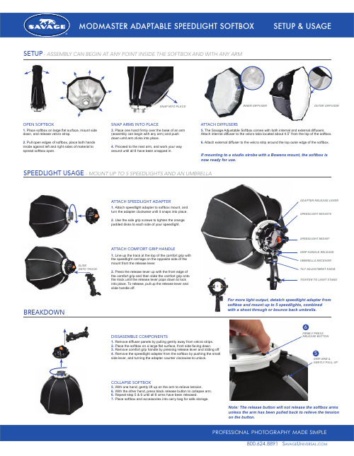
1. Place softbox on large flat surface, mount side down, and release velcro strap.2. Pull open edges of softbox, place both hands inside against left and right sides of material to spread softbox open.3. Place one hand firmly over the base of an arm (assembly can begin with any arm) and push down until arm clicks into place.4. Proceed to the next arm, and work your way around until all 8 have been snapped in.5. The Savage Adjustable Softbox comes with both internal and external diffusers. Attach internal diffuser to the velcro tabs located about 4.5” from the top of the softbox.6. Attach external diffuser to the velcro strip around the top outer edge of the softbox.If mounting to a studio strobe with a Bowens mount, the softbox is now ready for use.OPEN SOFTBOXSNAP ARMS INTO PLACEATTACH DIFFUSERSSNAP INTO PLACE INNER DIFFUSER SPEEDLIGHT MOUNTSADAPTER RELEASE LEVERSPEEDLIGHT MOUNTGRIP HANDLE RELEASE UMBRELLA RECEIVER TILT ADJUSTMENT KNOBTIGHTEN TO LIGHT STANDOUTER DIFFUSERSETUP- ASSEMBLY CAN BEGIN AT ANY POINT INSIDE THE SOFTBOX AND WITH ANY ARMSPEEDLIGHT USAGE- MOUNT UP TO 5 SPEEDLIGHTS AND AN UMBRELLAATTACH SPEEDLIGHT ADAPTERATTACH COMFORT GRIP HANDLEDISSASEMBLE COMPONENTSCOLLAPSE SOFTBOX1. Attach speedlight adapter to softbox mount, and turn the adapter clockwise until it snaps into place.2. Use the side grip screws to tighten the orange padded disks to each side of your speedlight.1. Line up the track at the top of the comfort grip with the speedlight carriage on the opposite side of the mount from the release lever.2. Press the release lever up with the front edge of the comfort grip and then slide the comfort grip onto the track until the release lever pops down to lock into place. To release, pull up the release lever and slide handle off.For more light output, detatch speedlight adapter from softbox and mount up to 5 speedlights, combinedwith a shoot through or bounce back umbrella.SLIDEONTO TRACK1. Remove diffuser panels by pulling gently away from velcro strips.2. Place the softbox on a large flat surface, front side facing down.3. Remove comfort grip handle by pressing release lever and sliding off.4. Remove the speedlight adapter from the softbox by pushing the small side lever, and turning the adapter counter clockwise to unlock.BREAKDOWNNote: The release button will not release the softbox arms unless the arm has been pulled back to relieve the tension on the button.145235. With one hand, gently lift up on the arm to relieve tension.6. With the other hand, press black release button to collapse arm.6. Repeat step 5 & 6 until all 8 arms have been released.7.Place softbox and accessories into carry bag for safe storage.GRIP ARM &5FIRMLY PRESS6a v age niversal com。
MODTRAN介绍使用
第一行:(CARD1参数,主要是大气模式方面的参数) CARD 1:FORMAT (2A1, I3, 12I5, F8.3, F7.0) 第二行:(CARD 1A 的参数) FORMAT (2L1, I3, L1, I4, F10.5, 2A10, 3(1X, A1), 4X, F10.3) (MOD4.0) 第三行: FORMAT(A80) 第四行:(CARD2 的参数,主要是气溶胶及云雨模式方面的参数) FORMAT (A2, I3, A1, I4, A3, I2, 3(I5), 5F10.5) 第五行:(CARD3 的参数,主要是探测几何方式方面的参数) FORMAT (6F10.3, I5, 5X, F10.3) 第六行:(CARD3 A1 的参数) FORMAT (415) 第七行:(CARD3 A2 的参数) FORMAT (8F10.3) 第八行:(CARD4 的参数,主要是波段及分辨率方面的参数) FORMAT (4F10.0, 2A1, A8, A7) 第九行:(CARD5 的参数) FORMAT (I5)
2. MODTRAN简介
2.1 MODTRAN及特点
(1)模式选择性强。可任意选择 LOETRAN7或MODTRAN辐射 传输模式,在选择的模式下,可以计算吸收物质的路径透射比、 大气辐射率、单次 (多次 )散射的太阳/月亮辐射率和直接透过的太 阳辐射等;
(2)辐射过程几乎考虑了大气中所有大气分子的吸收、散射和气 溶胶、云的吸收和散射效应;
+
b,i
( ,; ,)Lai tm ( ) cos d
]
atm i
+
Latm i
为到达传感 器的实际辐 射亮度;
穿透大气而进 入传感器的地 物的辐射亮度
MODTRAN5.2.2使用说明

MODTRAN®5.2.2 USER’S MANUALA. Berk *, G.P. Anderson #, P.K. Acharya *, E.P. Shettle ^* Spectral Sciences, Inc.4 Fourth AvenueBurlington, MA 01803-3304(lex@)# Air Force Research LaboratorySpace Vehicles DirectorateAir Force Materiel CommandHanscom AFB, MA 01731-3010(Gail.Anderson@)^ Naval Research LaboratoryRemote Sensing DivisionWashington, DC 20375-5351May 2011SPECTRAL SCIENCES, INC.4 Fourth Ave.Burlington, MA 01803-3304AIR FORCE RESEARCH LABORATORYSpace Vehicles DirectorateAIR FORCE MATERIEL COMMANDHANSCOM AFB, MA 01731-3010TABLE OF CONTENTSSection Page 1. INTRODUCTION (5)1.1 Changes from Mod5.2.0 to Mod5.2.1 (5)1.2 Changes from Mod5.2.1 to Mod5.2.2 (5)1.3 Original Introduction (5)2. OVERVIEW OF INPUT DATA FORMAT (6)2.1 Listing of MODTRAN®5 CARDs and Their Format (7)3. CARD 1 (REQUIRED) – MAIN Radiation Transport DRIVER (10)4. CARD 1A (REQUIRED) –RADIATIVE TRANSPORT DRIVER CONT’D (13)5. OPTIONAL CARDs 1A1, 1A2, 1A3, 1a4, 1A5, 1a6, 1A7, 1b (18)6. CARD 2 (REQUIRED) – MAIN aerosol and cloud options (21)7. OPTIONAL CARD 2A+ (FLEXIBLE AEROSOL MODEL) (25)8. OPTIONAL CARD 2A (CLOUD MODELS) (26)8.1 CARD 2A Standard Form (CIRRUS CLOUD MODELS, ICLD = 18 or 19) (26)8.2 CARD 2A Alternate Form (WATER/ICE CLOUD MODELS, ICLD = 1 - 10) (26)9. OPTIONAL CARD 2B (ARMY VERTICAL STRUCTURE ALGORITHM) (29)10. OPTIONAL CARDs 2C, 2CY, 2C1, 2C2, 2C2X, 2C2Y, 2C3 (29)10.1 CARD 2C (30)10.2 CARDs 2C1, 2C2, 2C2X, 2C2Y (31)10.3 CARD 2C3 (33)11. OPTIONAL CARDs 2D, 2D1, 2D2 (USER-DEFINED AEROSOL AND CLOUD PARAMETERS) (34)11.1 CARD 2D (34)11.2 CARD 2D1 (34)11.3 CARD 2D2 (34)12. OPTIONAL CARDs 2E1 AND 2E2 (USER-DEFINED CLOUD PARAMETERS) (35)12.1 CARD 2E1 (35)12.2 CARD 2E2 (36)12.3 Alternate CARD 2E2 (37)13. CARD 3 (REQUIRED) – LINE-OF-SIGHT GEOMETRY (38)13.1 Standard CARD 3 (38)13.2 Alternate CARD 3 (TRANSMITTED SOLAR/LUNAR IRRADIANCE, IEMSCT = 3) (40)14. OPTIONAL CARDs 3A1 AND 3A2 (SOLAR / LUNAR SCATTERING GEOMETRY) (41)14.1 CARD 3A1 (41)14.2 CARD 3A2 (41)15. OPTIONAL CARDs 3B1, 3B2, 3C1-3C6 (USER-DEFINED SCATTERING PHASE FUNCTIONS) (42)15.1 CARD 3B1 (43)15.2 CARD 3B2 (43)15.3 CARDs 3C1-3C6 (43)16. CARD 4 (REQUIRED) - SPectral range and resolution (44)17.OPTIONAL CARDs 4A, 4B1, 4B2, 4B3, 4L1 and 4L2 (46)17.1 CARD 4A (46)17.2 CARD 4B1 (47)17.3 CARD 4B2 (50)17.4 CARD 4B3 (50)17.5 CARD 4L1 (50)17.6 CARD 4L2 (51)18. CARD 5 (REQUIRED) – Repeat run option (51)19. DEDICATION AND aCKNOWLEDGEMENTS (52)20. REFERENCES (53)APPENDIX A: MODTRAN® USER-SUPPLIED AEROSOL UPGRADES (55)A.1 User-Supplied Aerosol Spectral Parameters (ARUSS Option) (55)A.3 User-Supplied Aerosol Profiles (CARD 2C3) (57)A.4 Example tape5 File (58)APPENDIX B: NOVAM IN MODTRAN® (58)B.1 NOVAM Code (58)B.2 Incorporation into MODTRAN® (60)B.3 Some Results (61)B.4 NOVAM input and MODTRAN® input Files (61)B.5 Future Upgrades to NOVAM Implementation (64)B.6 Modifications to NOVAM to Code (64)B.7 References (65)APPENDIX C: MODTRAN® INSTALLATION (65)C.1 MODTRAN5.2.1 PC Installation Steps (65)C.2 MODTRAN5.2.1 MAC Installation Steps (65)C.3 MODTRAN5.2.1 linux (UNIX) Installation Steps (65)C.4 I/O Files (66)APPENDIX D: BAND MODEL FILES FOR USER-DEFINED SPECIES (67)APPENDIX E: BINARY OUTPUT OPTION (68)APPENDIX F: SPECIAL DISORT OPTION FOR ATMOSPHERIC CORRECTION (69)APPENDIX G: MODTRAN FREQUENTLY ASKED QUESTIONS (FAQ) ............................................... V olume 2LIST OF TABLESTable Page Table 1. Columns List Allowed Values of MODTRAN®CARD 1Input Parameters MODTRN, SPEED, MODEL ITYPE, IEMSCT, IMULT, MDEF, NOPRNT and SURREF. (13)Table 2. Shows the Value of IVULCN Corresponding to the Different Choices of Extinction Coefficient Model and the Vertical Distribution Profile. (22)Table 3. MODTRAN® CARD 2 Input Parameters: IHAZE, ISEASN, IVULCN, VIS (23)Table 4. Default Wind Speeds for Different Model Atmospheres Used with the Navy Maritime Model (IHAZE = 3) (24)Table 5. MODTRAN® CARD 2 Input Parameter: ICLD (25)Table 6. Default Aerosol Region Boundaries. (26)Table 7. Properties of the MODTRAN® Cumulus and Stratus Type Model Clouds. (27)Table 8. Association of the JCHAR(J) Index (J = 1, 14) with the Variables P, T & WMOL. (31)Table 9. Various Names for the Heavy Molecular Gases, (WMOLX(J), J = 1, 13) (32)Table 10. VARSPC Fixed (Required) Wavelength Grid for the Multiply Read CARD 2D2 (35)Table 11. Default Values of the Earth Radius for Different Model Atmospheres. (38)Table 12. Allowed Combinations of Slant Path Parameters (40)Table 13. CARD 3A2: Options for Different Choices of IPARM (42)Table 14. MODTRAN® CARD 5 Input Parameter: IRPT. (52)1. INTRODUCTION1.1 Changes from Mod5.2.0 to Mod5.2.1Most changes in this revision are minor, such as correcting comments or removing unused source code. The more important changes are listed below:Corrected error in calculation of spherical albedo term in <rootname>.acd file;Corrected error in <rootname>.7sc brightness temperatures for nanometer based response functions;Eliminated geometry problem most prevalent for line-of-sight paths that terminate near a tangent point;Introduced the 2009 series of band model parameter data based on HITRAN2008 with 2009 updates.Added the <rootname>.wrn output file which contains a duplicate listing of all warning and errormessages written to the <rootname>.tp6 and <rootname>.tp8 files;Modified source for compatibility to GNU compilers and FORTRAN77; andEliminated DISORT scaling of thermal radiance contributions.1.2 Changes from Mod5.2.1 to Mod5.2.2The number of changes in this revision is small, and they are delineated below:Mod5.2.1 had an error in its treatment of the boundary term for down-looking radiance calculationswhich used DISORT multiple scattering; the sensor-to-ground attenuation was being modeled usingthe true transmittance when the delta-M transmittance should have been used. For particularwavelength bins, spectral radiances could be in error by as much as a few percent.MODTRAN *.tp6 output file lists the vertical and line-of-sight total path 550nm extinction opticaldepths for molecular scattering, the aerosol components and cirrus clouds. For calculations in thethermal infrared (TIR), for example, the visible wavelength optical depths are not particularly helpful.MODTRAN *.tp6 output file now also lists the vertical and line-of-sight total path extinction opticaldepths at the central frequency of the input spectral range for molecular scattering, the aerosolcomponents and cirrus clouds.The MODTRAN headed, which previously was only written to the *.tp6 file, is now included in thestandard output and in the *.wrn file. The header has been modified to remind users who obtainMODTRAN via a Government Purpose Use license that their copy of the model is only to be used forGovernment Purposes as described in the license. Finally, the header is now only written once to eachfile.MODTRAN now includes a frequently asked questions (FAQ) document. It is listed as Appendix G ofthis document, but distributed in a separate volume.1.3 Original IntroductionMODTRAN®[Berk et al., 1989; Berk et al., 1998; Berk et al., 2000] serves as the U.S. Air Force (USAF) standard moderate spectral resolution radiative transport model for wavelengths extending from the thermal Infrared (IR) through the visible and into the ultraviolet (0.2 to 10,000.0 m). The spectroscopy of MODTRAN®5.2.2 is based on HITRAN2008 line compilation (Rothman et al., 1992; Rothman et al., 1998) with updates through June, 2009. The original MODTRAN® 1 cm-1 statistical band model was developed collaboratively by Spectral Sciences, Inc. and the USAF Research Laboratory to provide a fast alternative to the first principles, high accuracy line-by-line (LBL) radiative transport approach. Comparisons between MODTRAN® and LBL [Clough and Kneizys, 1979; Clough et al., 1981; Clough, 1988; and Snell et al., 1995]. Comparisons between MODTRAN® and the LBL model FASE (FASCODE for the Environment) [Clough et al., 1992; Clough and. Iacono, 1995; Clough et al., 2005] spectral transmittances and radiances show agreement to within a few percent or better in the thermal IR. FASE shares its LBL line shape fitting algorithms with LBLRTM, which evolved from FASCODE; see, for instance, Clough et al., 1992; Clough and. Iacono, 1995; Clough et al., 2005]. The MODTRAN®model includes flux and atmosphere-scattered solar calculations, essential components in analysis of near-IR and visible spectral region data that are not readily generated by LBL models.Technical descriptions of the MODTRAN®5 approach are available from a variety of sources. The original MODTRAN®2 code and many of the MODTRAN®3 upgrades are described in the 1996 report "MODTRAN® 2/3Report and LOWTRAN 7 Model" [Abreu and Anderson, 1996]. The current documentation incorporates material from that report, from Section 3 of the 1988 Users Guide to LOWTRAN7 [Kneizys et al., 1988], from the 1989 Air Force Research Laboratory (AFRL) report on the MODTRAN® band model [Berk et al., 1989], and from the 1996 Spectral Sciences, Inc. report on the cloud and rain model upgrades [Berk and Anderson, 1995]. Articles [Bernstein et al., 1995; Berk et al., 1998] discuss improvements to the band model. P lease email “Gail P. Anderson” <Gail.Anderson@>; “Michael L Hoke” <Michael.Hoke@> and / or “Alexander Berk” <lex@> for additional information on MODTRAN®5.MODTRAN®5 upgrades and improvements take the utility and science of the code to a new level, which includes, among other features, a much finer spectroscopy – spectral resolution can now be as fine as 0.1 cm-1– and the ability to handle new species not already included in the built-in profile and molecular parameter files. A summary of new features include:Reformulating the band model parameters and radiation transport formalism to increase the resolutionof MODTRAN® spectral calculations to 0.1 cm-1;Increasing the TOA solar database resolution to 0.1 cm-1;Incorporating code interface changes between MODTRAN® and DISORT to increase its speed andaccuracy of multiple scattering calculations;Upgrading MODTRAN®to perform spectral radiance computations for auxiliary molecules (byincluding their concentrations and spectral parameters) that are not part of the traditionalMODTRAN® database; Band models are provided for all HITRAN molecular species;Incorporating effect of a thin layer of water, which can either simply wet the ground or accumulate onit, on radiance computations;Capability to model a boundary layer aerosol whose extinction coefficient obeys the Angstrom law orto modify the extinction of a model aerosol with an Angstrom law perturbation;Capability to determine the spherical albedo and reflectance of the atmosphere and diffusetransmittance from a single MODTRAN® run;Ability to include only the solar contribution to multiple scattering and ignore the thermal componentwhere it is not significant;Option to write spectral output in binary, and a utility to convert the binary output to ASCII;Capability to process several tape5 input files by a single execution of MODTRAN®;Upgrade to the MODTRAN®-DISORT interface so that only a single parameter (MXCMU in routinePARAMS.h) needs to be modified to change the maximum number of streams available for DISORTruns.Added dithering of the solar angle in cases where the DISORT particular solution to the solar problemwas unstable.And more ….These user instructions for MODTRAN®5.2.2 describe each input in the MODTRAN®input files, tape5 or rootname.tp5.2. OVERVIEW OF INPUT DATA FORMATMODTRAN®5 makes it easy for the users to keep track of input and output (I/O) files. A MODTRAN® input file named either 'mod5root.in' or 'MOD5ROOT.IN' contains a list of file root names. If 'mod5root.in' does not exist, MODTRAN®checks for the existence of a 'MOD5ROOT.IN' file. If neither of these files exists, MODTRAN® I/O files are the traditional ones: 'tape5', 'tape6', 'tape7', 'tape8', etc. If a root name file exists and its very first line contains a non-null string (maximum length is 80 characters), this string is treated as a prefix. If the string consists of all blanks or is a null string, the traditional I/O file names are assumed. The root name should contain no embedded blanks; leading and trailing blanks are properly ignored. If the rootname file has the extension “.tp5”, this extension is also ignored. The character string is used as a prefix for the I/O files whose names have mnemonic suffixes. As an example, if the string is Denver, the MODTRAN® I/O files will have these names:Overview of Input Data FormatDenver.tp5(corresponding to tape5)Denver.tp6(corresponding to tape6)Denver.tp7(corresponding to tape7)Denverb.tp7(corresponding to tape7b)Denver.tp8(corresponding to tape8)Denverb.tp8(corresponding to tape8b)Denver.7sc(corresponding to tape7.scn)Denver.7sr(corresponding to tape7.scr)Denver.plt(corresponding to pltout)Denverb.plt(corresponding to pltoutb)Denver.psc(corresponding to pltout.scn)Denver.clr(corresponding to clrates)Denver.chn(corresponding to channels.out)Denver.flx(corresponding to specflux)Denver.acd(corresponding to atmcor.dat)A useful feature of MODTRAN®5 is the ability to process several input files in a single execution of MODTRAN®. To accomplish this, list the rootname of each input file as consecutive lines (without intervening blank lines) in 'mod5root.in' or 'MOD5ROOT.IN'. When the user executes MODTRAN®, each input ‘.tp5’ file, whose rootname is listed in 'mod5root.in' or 'MOD5ROOT.IN', is processed until the first blank line is encountered. Any ‘.tp5’ file whose rootname is encountered after the first blank line is not processed.As noted above, MODTRAN®is controlled by a input file, 'tape5' or 'rootname.tp5', which consists of a sequence of six or more formatted CARDS (inputs lines). The input file format is summarized below. With the exception of file names, character inputs are case insensitive. Also, blanks are read in as zeroes for numerical inputs, and as default values otherwise. Detailed descriptions of the card formats and parameters are given in the following sections.2.1 Listing of MODTRAN®5 CARDs and Their FormatIn the following, optional cards are indented. The mandatory input CARDS are CARD 1, CARD 1A, CARD 2, CARD 3, CARD 4 and CARD 5. Newer inputs are in Italics. Note that all floating point inputs are entered using a ‘Fn.0’ format; this format will properly read any floating point entry, e.g. ‘1.234’, AND will also properly read integers as floating point real variables, (either 1234. or 1234 with no decimal).CARD 1: MODTRN, SPEED, BINARY, LYMOLC, MODEL, T_BEST, ITYPE, IEMSCT, IMULT, M1, M2, M3, M4, M5, M6, MDEF, I_RD2C, NOPRNT, TPTEMP, SURREFFORMAT (4A1, I1, A1, I4, 10I5, 1X, I4, F8.0, A7)CARD 1A:DIS, DISAZM, DISALB, NSTR, SFWHM, CO2MX, H2OSTR, O3STR, C_PROF, LSUNFL, LBMNAM, LFLTNM, H2OAER, CDTDIR, SOLCON, CDASTM, ASTMC, ASTMX, ASTMO,AERRH, NSSALBFORMAT(3A1, I3, F4.0, F10.0, 2A10, 2A1, 4(1X, A1), F10.0, A1, F9.0, 3F10.0, I10) CARD 1A1:USRSUNFORMAT (A256) (If LSUNFL = 'T') CARD 1A2: BMNAMEFORMAT (A256) (If LBMNAM = 'T', 't', '4' or '2') CARD 1A3: FILTNMFORMAT (A256) (If LFLTNM = 'T') CARD 1A4: DATDIRFORMAT (A256) (If CDTDIR = 'T')Overview of Input Data FormatCARD 1A5: (S_UMIX(IMOL), IMOL = 4, 12)FORMAT (9F5.0) (If C_PROF = 1, 3, 5 or 7) CARD 1A6: (S_XSEC(IMOL), IMOL = 1, 13)FORMAT (13F5.0) (If C_PROF = 2, 3, 6 or 7) CARD 1A7: (S_TRAC(IMOL), IMOL = 1, 16)FORMAT (16F5.0) (If C_PROF = 4, 5, 6 or 7) CARD 1B:(AWAVLN(ISSALB), ASSALB(ISSALB), ISSALB=1, NSSALB)FORMAT ((8F10.0)) (If NSSALB > 0) Alternate CARD 1B:ACOALB, RHASYMFORMAT(2F10.0) (If NSSALB < 0) CARD 2:APLUS, IHAZE, CNOVAM, ISEASN, ARUSS, IVULCN, ICSTL, ICLD, IVSA, VIS, WSS, WHH, RAINRT, GNDALTFORMAT (A2, I3, A1, I4, A3, I2, 3I5, 5F10.0)CARD 2A+:ZAER11, ZAER12, SCALE1, ZAER21, ZAER22, SCALE2, ZAER31, ZAER32, SCALE3, ZAER41, ZAER42, SCALE4FORMAT ((3(1X, F9.0), 20X, 3(1X, F9.0))) (If APLUS = 'A+') CARD 2A:CTHIK, CALT, CEXTFORMAT (3F8.0) (If ICLD = 18 or 19) Alternate CARD 2A:CTHIK, CALT, CEXT, NCRALT, NCRSPC, CWAVLN, CCOLWD, CCOLIP, CHUMID, ASYMWD, ASYMIPFORMAT (3F8.0, 2I4, 6F8.0) (If 0 < ICLD ≤ 10) CARD 2B:ZCVSA, ZTVSA, ZINVSAFORMAT (3F10.0) (If IVSA = 1) CARD 2C:ML, IRD1, IRD2, HMODEL, REE, NMOLYC, E_MASS, AIRMWTFORMAT(3I5, A20, F10.0, I5, 2F10.0) (If MODEL = 0, 7 or 8; & I_RD2C = 1) CARD 2CY: (YNAME(I), I=1, NMOLYC)FORMAT ((8A10)) (If NMOLYC > 0) CARDs 2C1, 2C2, 2C2X, 2C2Y and 2C3 (as required) are each repeated ML times.CARD 2C1:ZM, P, T, WMOL(1), WMOL(2), WMOL(3), (JCHAR(J), J = 1, 14), JCHARX, JCHARY FORMAT 6F10.0, 14A1, 1X, 2A1)CARD 2C2:(WMOL(J), J = 4, 12)FORMAT (8F10.0, /F10.0) (If IRD1 = 1) CARD 2C2X:(WMOLX(J), J = 1, 13)FORMAT (8F10.0, /5F10.0) (If MDEF = 2 & IRD1 = 1) CARD 2C2Y: (WMOLY(J), J = 1, NMOLYC)FORMAT ((8F10.0)) (If NMOLYC > 0 & IRD1 = 1) CARD 2C3:AHAZE, EQLWCZ, RRATZ, IHA1, ICLD1, IVUL1, ISEA1, ICHRFORMAT (10X, 3F10.0, 5I5) (If IRD2 = 1) CARD 2C3: AHAZE(1), RRATZ, AHAZE(2), AHAZE(3), AHAZE(4)FORMAT(10X, F10.0, 10X, 4F10.0) (If IRD2 = 2) CARD 2D:(IREG(N), N = 1, 2, 3, 4)FORMAT (4I5) (If IHAZE = 7, ICLD = 11 or ARUSS=’USS’)CARDs 2D1 and 2D2 pairs are repeated for each N (1 to 4) for whichIREG(N) > 0 and ARUSS=USS or IREG(N) ≠ 0 and (IHAZE=7 or ICLD=11)CARD 2D1:AWCCON, AERNAMFORMAT (F10.0, A70)CARD 2D2:(VARSPC(N, I), EXTC(N, I), ABSC(N, I), ASYM(N, I), I = l, 2, ..., I max)If ARUSS = 'USS' & IREG(N) > 1, then I max = IREG(N); Else I max = 47 FORMAT ((3(F6.2, 2F7.5, F6.4)))CARD 2E1:(ZCLD(I, 0), CLD(I, 0), CLDICE(I, 0), RR(I, 0), I = 1, NCRALT)FORMAT ((4F10.5)) (If ICLD = 1 - 10, NCRALT 2, MODEL < 8) Alternate CARD 2E1:(PCLD(I, 0), CLD(I, 0), CLDICE(I, 0), RR(I, 0), I = 1, NCRALT)FORMAT ((4F10.5)) (If ICLD = 1 - 10, NCRALT 2, MODEL = 8) CARD 2E2:(WAVLEN(I), EXTC(6, I), ABSC(6, I), ASYM(6, I), EXTC(7, I), ABSC(7, I), ASYM(7, I),I = 1, NCRSPC)FORMAT ((7F10.5)) (If ICLD = 1 - 10, NCRSPC 2) Alternate CARD 2E2:C FILE, CLDTYP, CIRTYPFORMAT ((A256)) (If ICLD = 1 - 10, NCRSPC = 1) CARD 3: H1, H2, ANGLE, RANGE, BETA, RO, LENN, PHIFORMAT (6F10.0, I5, 5X, 2F10.0)Alternate CARD 3:H1, H2, ANGLE, IDAY, RO, ISOURC, ANGLEMFORMAT (3F10.0, I5, 5X, F10.0, I5, F10.0) (If IEMSCT = 3) CARD 3A1:IPARM, IPH, IDAY, ISOURCFORMAT (4I5) (If IEMSCT = 2 or 4) CARD 3A2: PARM1, PARM2, PARM3, PARM4, TIME, PSIPO, ANGLEM, GFORMAT (8F10.0) (If IEMSCT = 2 or 4) CARD 3B1: NANGLS, NWLFFORMAT (2I5) (If IEMSCT = 2 or 4; IPH = 1)CARD 3B2:(ANGF(I), F(1, I, 1), F(2, I, 1), F(3, I, 1), F(4, I, 1), I = l, NANGLS)FORMAT (5F10.0) (If IEMSCT = 2 or 4; IPH = 1; NWLF = 0) CARD 3C1:(ANGF(I), I = 1, NANGLS)FORMAT (8F10.0) (If IEMSCT = 2 or 4; IPH = 1; NWLF > 0) CARD 3C2:(WLF(J), J = 1, NWLF)FORMAT (8F10.0) (If IEMSCT = 2 or 4; IPH = 1; NWLF > 0) In CARDs 3C3-3C6, 'IANG' is angle index as in CARD 3C1and 'JWAV' is the wavelength index as in CARD 3C2.CARD 3C3:(F(1, IANG, JWAV), JWAV = 1, NWLF)FORMAT (8F10.0) (If IEMSCT = 2 or 4; IPH = 1; NWLF > 0) CARD 3C4:(F(2, IANG, JWAV), JWAV = 1, NWLF)FORMAT (8F10.0) (If IEMSCT = 2 or 4; IPH = 1; NWLF > 0) CARD 3C5: (F(3, IANG, JWAV), JWAV = 1, NWLF)FORMAT (8F10.0) (If IEMSCT = 2 or 4; IPH = 1; NWLF > 0) CARD 3C6:(F(4, IANG, JWAV), JWAV = 1, NWLF)FORMAT (8F10.0) (If IEMSCT = 2 or 4; IPH = 1; NWLF > 0) CARD 4:V1, V2, DV, FWHM, YFLAG, XFLAG, DLIMIT, FLAGS, MLFLX, VRFRACFORMAT (4F10.0, 2A1, A8, A7, I3,F10.0)CARD 4A:NSURF, AATEMP, DH2O, MLTRFLFORMAT (I1, 2F9.0, A1) (If SURREF = 'BRDF' or 'LAMBER') The set of CARD4B1, 4B2, and 4B3 inputs is repeated NSURF times.CARD 4B1:CBRDFFORMAT (A80) (If SURREF = 'BRDF') CARD 4B2:NWVSRF, SURFZN, SURFAZFORMAT (*) (If SURREF = 'BRDF') CARD 4B3 is repeated NWVSRF times.CARD 4B3:WVSURF, (PARAMS(I), I = 1, NPARAM)FORMAT (*) (If SURREF = 'BRDF')CARD 4L1:SALBFLFORMAT (A256) (If SURREF = 'LAMBER') CARD4L2 is repeated NSURF times.CARD 4L2:CSALBFORMAT (A80) (If SURREF = 'LAMBER') CARD 5: IRPTFORMAT (I5)3. CARD 1 (REQUIRED) – MAIN RADIATION TRANSPORT DRIVERAlthough CARD 1 format has been modified over the years, the format is backward compatible if inputs are right justified.CARD 1: MODTRN, SPEED, BINARY, LYMOLC, MODEL, T_BEST, ITYPE, IEMSCT, IMULT, M1, M2, M3, M4, M5, M6, MDEF, I_RD2C, NOPRNT, TPTEMP, SURREFFORMAT (4A1, I1, A1, I4, 10I5, 1X, I4, F8.0, A7)MODTRN selects the band model algorithm used for the radiative transport, either the moderate spectral resolution MODTRAN®band model or the low spectral resolution LOWTRAN band model. LOWTRAN spectroscopy is obsolete and is retained only for backward compatibility. The MODTRAN® band model may be selected either with or without the Correlated-k treatment.MODTRN = 'T', 'M' or blank MODTRAN® band model.= 'C' or 'K' MODTRAN® correlated-k option (IEMSCT radiance modes only; mostaccurate but slower run time).= 'F' or 'L' 20 cm-1LOWTRAN band model (not recommended except for quickhistoric comparisons).SPEED = 'S' or blank 'slow' speed Correlated-k option using 33 absorption coefficients (kvalues) per spectral bin (1 cm-1or 15 cm-1). This option isrecommended for upper altitude (> 40 km) cooling-rate and weighting-function calculations only.= 'M' 'medium' speed Correlated-k option (17 k values).BINARY = 'F' or blank All outputs are in ASCII (normal situation).= 'T' The tape7 (.tp7), tape8 (.tp8), plot (.plt), flux (.flx) and atmosphericcorrection data (.acd) files are all generated by MODTRAN® in binaryformat. The ASCII versions are retrieved by running the auxiliaryprogram M5_bn2as.f. See Appendix E for details.LYMOLC = '+' Include 16 auxiliary trace species when either a model atmosphere isselected (MODEL = 1 to 6) or a user-defined atmosphere is selected(MODEL = 0, 7 or 8) AND input NMOLYC (CARD 2C) is zero. Inthe latter case, NMOLYC is reset to 16 requiring that both JCHARY(CARD 2C1) and CARDs 2C2Y be read in. The 16 auxiliary tracespecies are referred to as “Y” species within the source code.Thespecific 16 species, in order, are OH, HF, HCl, HBr, HI, ClO, OCS,H2CO, HOCl, N2, HCN, CH3Cl, H2O2, C2H2, C2H6, and PH3.= blank Do not include auxiliary species with model atmosphere.CARD 1 (Required)MODEL selects one of the six geographical-seasonal model atmospheres or specifies that user-defined meteorological or radiosonde data are to be used.MODEL = 0 If single-altitude meteorological data are specified (constant pressure, horizontal path only;see instructions for CARDs 2C, 2C1, 2C2, 2C2X, 2C2Y and 2C3).1 Tropical Atmosphere (15 North Latitude).2 Mid-Latitude Summer (45 North Latitude).3 Mid-Latitude Winter (45 North Latitude).4 Sub-Arctic Summer (60 North Latitude).5 Sub-Arctic Winter (60 North Latitude).6 1976 US Standard Atmosphere.7 If a user-specified model atmosphere (e.g. radiosonde data) is to be read in; see instructionsfor CARDs 2C, 2C1, 2C2, 2C2X, 2C2Y and 2C3.8 Pressure-dependent atmospheric profiles. A user-specified model atmosphere (e.g.radiosonde data) is to be read in with altitudes determined from the pressure profile bysolving the hydrostatic equation. See instructions for I_RD2C on CARD 1and forCARDs 2C, 2C1, 2C2, 2C2X, 2C2Y and 2C3 for further details.T_BEST provides a debug option for the Voigt single line finite bin transmittance calculation. This option is very slow and requires a FORTRAN90 executable. The results should be in very good agreement with MODTRAN run in normal mode, i.e. with the standard Voigt single line finite bin transmittance algorithm. This option should only be used if one has reasons to suspect that MODTRAN transmittances are in error, and one wishes to verify that the problem is not caused that the MODTRAN Voigt transmittance algorithm.T_BEST = ″T″ or ″t″Use benchmark Voigt single line finite bin transmittance algorithm.Otherwise Use MODTRAN standard Voigt single line finite bin transmittance algorithm.ITYPE indicates a geometric type for the atmospheric line-of-sight (LOS) path.ITYPE = 1 Horizontal (constant-pressure) path, i.e., flat Earth constant altitude path.2 Vertical or slant path between two altitudes.3 Vertical or slant path to space or ground.IEMSCT determines the radiation transport mode of execution of the program.IEMSCT = 0 Program executes in spectral transmittance only mode.1 Program executes in spectral thermal radiance (no sun / moon) mode.2 Program executes in spectral thermal plus solar / lunar radiance mode (if IMULT = 0, onlysingle scatter solar radiance is included).3 Program calculates directly transmitted spectral solar / lunar irradiance.4 Program executes in spectral solar / lunar radiance mode with no thermal scatter. Thermalpath and surface emission is included.IMULT determines inclusion of multiple scattering (MS).IMULT = 0 Program executes without multiple scattering.±1 Program executes with multiple scattering.IEMSCT must equal 1, 2 or 4 to execute with multiple scattering. MS contributions are calculated using plane parallel geometry (the solar illumination impingent upon each atmospheric level (altitude) is determined with spherical refractive geometry, important for low sun angles, when the ISAACS MS model is selected on CARD 1A but not with DISORT MS). If IMULT = 1, the solar geometry at the location of H1 (latitude and longitude) is used in the MS calculation; if IMULT = -1, the MS calculation is instead referenced to H2. The quantity H2 is the final path altitude unless ITYPE = 3 and H2 0; in that case, the MS plane parallel atmosphere is defined near the tangent point of the limb path. (The path zenith of 90° at the tangent point is a forbidden input to the plane-parallelCARD 1 (Required)MS models because it leads to a mathematical singularity.) For simulation of sensors on satellite platforms, IMULT should generally be set to -1 since MS will only be significant nearer to H2 (the surface or tangent height).M1, M2, M3, M4, M5, M6, and MDEF are used to modify or supplement user-specified altitude profiles for temperature, pressure, and default molecular gases: H2O, O3, CH4, N2O, CO, CO2, O2, NO, SO2, NO2, NH3, HNO3, and 13 “heavy molecules.” For operation of the program using the standard model atmospheres (MODEL 1 to 6), the CARD1 profile inputs M1, M2, M3, M4, M5, M6 and MDEF are all overwritten with values appropriate for the standard models.If MODEL equals 0 (horizontal path) or equals 7 or 8 (radiosonde data) and if M1 through M6 are set to zero or left blank and MDEF is set to -1, then the JCHAR parameter on each CARD 2C1 must be defined to supply the necessary profiles. If M1 through M6 are non-zero and MDEF not equal to -1, then the chosen default profiles will be utilized only if a specific JCHAR input is blank:M1 = 1 to 6 Default temperature and pressure to specified model atmosphere.M2 = 1 to 6 Default H2O to specified model atmosphere volume mixing ratio.= -1 to -6 Default H2O to specified model (= |M2|) atmosphere relative humidity.M3 = 1 to 6 Default O3 to specified model atmosphere.M4 = 1 to 6 Default CH4 to specified model atmosphere.M5 = 1 to 6 Default N2O to specified model atmosphere.M6 = 1 to 6 Default CO to specified model atmosphere.MDEF = 0 or 1 Default CO2, O2, NO, SO2, NO2, NH3, and HNO3 species profiles.Note that for H2O there are 2 options. With a positive value of M2, the H2O concentration is only a function of altitude and model profile. When a negative value of M2 is selected, the model atmosphere relative humidity is held constant. Thus, with this later option, a change in the temperature profile will result in a change in the water concentration. The positive M2 option is preferred when one desires a H2O profile that is independent of the temperature profile; the negative M2 option can be used to insure that over saturation (RH > 100%) is avoided.If MDEF = 1, default heavy species profiles are used. If MDEF = 2, the user must input the profiles for the heavy species, which include nine chlorofluorocarbons (CFCs) plus ClONO2, HNO4, CCl4, and N2O5. The 1 cm-1 absorption cross-sections are stored in "DATA/CFC99_01.ASC"; "DATA/CFC99_15.ASC" is the 15 cm-1 version of the file. The specification of user-defined profiles is modeled after the MODEL = 7 option in LOWTRAN, but only one unit definition (see JCHARX definition in CARD 2C1) can be used for the whole set of heavy species. The "default" profiles for these species are stored in BLOCK DATA /XMLATM/ and are based on 1990 photochemical predictions (after M. Allen, JPL). Since some of the CFCs have increased by as much as 8% per year, the user might well wish to redefine these values. Note that both CFC11 and CFC12 are now as much as 80% larger than the default profiles.If MODEL = 0, 7 or 8, MODTRAN® expects to read user-supplied atmospheric profiles. Set I_RD2C = 1 for the first run. To sequentially rerun the same atmosphere for a series of cases, set I_RD2C to 0 in subsequent runs; MODTRAN® will then reuse the previously read data and not read in CARD 2C, 2C1, … inputs.I_RD2C = 0 For normal operation of program or when calculations are to be run with the atmosphere MODEL last read in.= 1 When user input data are to be read.NOPRNT = 0 Normal writing to tape6 and tape7.= 1 Create a tape6 with no writing out of model atmosphere profiles.= 2 Create a tape6 with no spectral data or writing of model atmosphere profiles.= 3 Delete tape6 at end of processing if run is successful.= −1 Create additional tape8 output, including either weighting functions in transmission mode (IEMSCT = 0) or fluxes in radiation modes with multiple scattering on (IMULT = 1 andIEMSCT = 1, 2 or 4).= −2 Generates spectral cooling rate data in addition to the tape8 output; spectral cooling rates are written to the 'clrates' or 'rootname.clr' file.。
MODTRANTP5文件参数设置说明
MODTRANTP5文件参数设置说明MODTRAN (MODerate resolution atmospheric TRANsmission) is a software package widely used for modelling the transmission of electromagnetic radiation through the Earth's atmosphere. TheTP5 file is a text file that contains parameters necessary for running MODTRAN simulations. In this article, we will discuss the various parameters and their settings in the TP5 file.1.VERSIONThe VERSION parameter specifies the version of MODTRAN being used. It should be set to the appropriate version number.2.OPTIONSThe OPTIONS parameter controls the type of simulation to be performed. It is a bitwise sum of various integer values that correspond to different simulation options. For example, setting OPTIONS to 1 will perform a radiance calculation, while setting it to 4 will perform a visibility calculation. Multiple options can be selected by summing the corresponding values.3.RANGESThe RANGES parameter specifies the wavelength range over which the simulation will be performed. It is specified as two integers representing the lower and upper limits of the range,in nanometers.4.REFRACTIVITYThe REFR activity parameter controls the modeling of refractivity in the atmosphere. It can be set to either 0 (no refraction), 1 (ignore dispersion), or 2 (include dispersion).5.WATER6.OZONEThe OZONE parameter specifies the total columnar amount of ozone in the atmosphere, in Dobson Units (DU). It affects the calculation of transmittance in the ultraviolet region.7.AEROSOLSThe AEROSOLS parameter controls the modeling of aerosols in the atmosphere. It can be set to either 0 (no aerosols), 1 (urban aerosols), or 2 (continental aerosols).8.ALTITUDESThe ALTITUDES parameter specifies the altitude levels at which calculations will be performed. It is specified as a list of integers representing the altitude levels, in kilometers.9.SOLARThe SOLAR parameter specifies the solar spectrum to be used in the simulation. It can be set to either 0 (extraterrestrial spectrum), 1 (solar constant), or 2 (constant solar spectral irradiance).10.GROUNDThe GROUND parameter specifies the type of ground surface to be simulated. It can be set to either 0 (flat surface), 1 (Lambertian surface), or 2 (user-defined BRDF).11.VIEWINGThe VIEWING parameter specifies the atmospheric pathway for the observer. It can be set to either 0 (vertical path), 1 (slant path), or 2 (user-defined).12.ANGLESThe ANGLES parameter specifies the viewing and solar angles to be used in the simulation. It is specified as a list of integers representing the azimuth and zenith angles of the observer and the sun, respectively.These are some of the key parameters and their settings in the MODTRAN TP5 file. Other parameters like aerosol models,solar zenith angles, and atmospheric profiles can also be modified as per the requirements of the simulation. Understanding and configuring these parameters accurately is crucial for obtaining accurate and meaningful results from the MODTRAN simulations.。
- 1、下载文档前请自行甄别文档内容的完整性,平台不提供额外的编辑、内容补充、找答案等附加服务。
- 2、"仅部分预览"的文档,不可在线预览部分如存在完整性等问题,可反馈申请退款(可完整预览的文档不适用该条件!)。
- 3、如文档侵犯您的权益,请联系客服反馈,我们会尽快为您处理(人工客服工作时间:9:00-18:30)。
对流层顶部 (2-10km)的气溶胶比边界层均匀的多,大颗粒迅速减少。同流层 底部 (10-30km)的气溶胶主要受季节影响,因为对流层顶部的高度是随季节变化 的变化。该层呈全球均匀分布,不受地理环境影响,主要颗粒是光化学反应产生 的硫酸盐颗粒和火山喷发时的火山灰。高层大气的主要气溶胶是流星灰。 2.4 大气模型 MODTRAN定义了6种标准的大气模型,也允许用户输入气象数据,自定义 大气模型。标准的大气模型有:
边界层可以是地球、云、飞机等,MODTRAN假设边界层均为灰体,用户 须输入边界层温度和表面反射率(Surface Albedo) ,以确定表面发射的辐亮度。 边界层温度的缺省值为0,此时边界层温度根据大气模型确定。如不用缺省值, 用户可输入边界层的绝对温度和表面反射率。比辐射率等于(1-表面反射率) , 表面反射率的缺省值为0,比辐射率等于1,即认为是黑体。
气溶胶分布与海拔高度有关, MODTRAN 按高度将大气分为 4 层, 分别建立 气溶胶模型。 1)边界层 (0-2km); 2)对流层顶部 (2-10km); 3)同流层底部 (10-30km); 4)同流层(中间层) (30-100km)。
边界层气溶胶模型与地理环境、天气一个,MODTRAN给出的边界层气溶胶 模型主要有:农村、都市、海洋、对流层、雾等。
透过率运行模式下,可输出以下结果: 1)总路径透过率; 2)H2O,CO2,O3 等吸收气体的透过率; 3)分子散射的透过率;
9
4)气溶胶透过率。
3.1.4.2 热辐射亮度
热辐射亮度模式(MODE=1)可计算路径大气辐射的辐亮度(即大气辐亮度) 和路径的总透过率,大气辐射主要在热红外波段,故称大气热辐射。
1.2 输入文件 1.2.1 数据库文件 文件名.LTN, 包含 Modtran 模型参数的输入文件和输出曲线打印方式的输入 文件。
1
1.2.2 NOVAM 参数文件: 文件名.NPR,6000 米以下海面气溶胶分布,较以前海洋气溶胶模型有明显 改进。 1.2.3 滤波器函数文件: 文件名.FLT 滤波器函数可用于计算有效大气透过率或有效路径辐亮度。滤波器函数包含 辐射源的光谱特性和辐射测量仪器的光谱带通特性。 辐射源的光谱特性用黑体温 度表示,仪器光谱特性取决于探测器光谱响应和光学元件光谱透过或反射特性, Modtran 可设置最多 80 个波数点的相对响应。 1.2.4 扫描函数文件: 文件名.SCN Modtran 内部计算样点的光谱间隔为 1cm-1,为降低输出数据的光谱分辨率, Modtran 提供了扫描功能,可将输出光谱数据与一个狭缝函数进行卷积运算。狭 缝函数可以是三角形、矩形、Sinc.、Sinc.平方等函数。 FWHM 是狭缝函数的半宽度,最小设置值 2cm-1,最大设置值 50cm-1。因此, Modtran 输出数据光谱分辨率的极限为 2cm-1。
用户可直接输入反射率的数值, MODTRAN也提供了几种典型的边界层, 包 括:雪、森林、植被、草地、海洋、沙漠等,这几种典型边界层在红外波段的光 谱反射率和光谱比辐射率都是确定的。例如:
10
6)总辐亮度(Total Radiance) - 观察点在视线方向接收到辐射的总辐亮度。总辐亮度是 2) 、3) 、4) 、5) 四项辐亮度之和,由于热散射 3)和地面反射辐亮度 5)可忽略,总辐亮度 是路径热辐射 2)和边界层热辐射 4)辐亮度之和。 7)光学深度(Optical Depth) -单位:Km-1,应是衰减系数,光学深度(大气质量)是衰减系数对路径 的积分。
பைடு நூலகம்
MODTRAN 大气透过计算包括:
1)气体分子谱线吸收;
3
2)气体分子连续吸收; 3)气体分子散射; 4)气溶胶吸收和散射;
MODTRAN 路径辐亮度计算包括: 1)大气自身辐射; 2)以单次散射方式进入路径的太阳和/或月亮辐亮度; 3)斜路径对天观察时的直接太阳辐照度; 4)以多次散射方式进入路径的太阳和/或月亮辐亮度以及地球辐亮度。 2.2 大气路径类型与参数 MODTRAN 计算时,要求先输入路径类型,再输入路径参数。 2.2.1 水平路径 确定水平路径只需输入 2 个参数,即观察点高度、路径长度。这里的水 平路径系短路径,不是长路径。
8
3.1.1 计算选择
可选MODTRAN带模型或MODTRAN所含的LOWTRAN模型。 3.1.2 大气模型
大气模型包括标准大气模型和用户自定义。标准模型大气与 LOWTRAN相 同,共6种,其中1976年美国标准大气是一种标准的大气模型,其余5种模型反映 了季节、纬度对大气性质的影响。用户自定义大气模型有两种,要求用户输入气 象数据。 3.1.3 路径类型
MOD37 使用要点
1
MODTRAN 文件
1.1 输出文件 输入 Edit|Edit File 可查看运行 Modtran 产生的 ASCII 数据文件, 在 usr 目录 下有: Modout1、Modout2、Modout3
Modout1 包含完整结果,波段平均透过率、辐亮度在最后一段。
INTEGRATED ABSORPTION FROM AVERAGE TRANSMITTANCE = 0.7058 INTEGRATED TOTAL RADIANCE = 625 TO 25000 CM-1 )
6
农村的气溶胶模型由占比70%的可溶物质(氨、硫酸钙及有机化合物)和占 比30%类灰尘气溶胶混合而成。海洋的气溶胶模型由盐颗粒和背景两部分组成, 盐颗粒是海水飞沫蒸发后再凝聚核水汽形成的较大颗粒,存在于离海面10-20 米高处。海洋的背景气溶胶与陆地农村气溶胶相仿,唯一不同是没有非常大的颗 粒。都市气溶胶模型由占比20%的燃烧生成物或工业源形成的类烟尘气溶胶,其 余80%为农村气溶胶。对流层气溶胶模型代表了一种非常清彻天气条件,能见度 达50公里。
4
2.2.2 斜路径
可选用的斜路径参数包括: H1: H2: 初始高度(观察点高度) ; 最终高度(辐射源高度) ;
HMIN:正切高度,仅用于长程。正切高度是路径至地球的最低高度。
r:
起点与终点之间的直线距离,由于大气折射,长路径时,实际路 径的长度大于此值。
: 天顶角,观察点的重垂线与路径的夹角;
7
3
MODTRAN 屏幕输入 MODTRAN 的屏幕输入参数有模型大气( Model Atmosphere ) 、气溶胶
(Aerosol)、几何参数和光谱带 (Geometry and Spectral Band)等 3 大类,参数输入 屏幕上分别用(1) 、 (2) 、 (3)标注。 3.1 “模型大气”输入参数 屏幕标题:Model Atmosphere(1)
: 最终角,源点的重垂线与路径的夹角;
:
地心对观察点、源点的张角。
确定一个斜路径只需输入 3 个参数,共有 6 种设置方法: 1)H1, ,H2; 2)H1, , r ; 3)H1,H2, r ; 4)H2,H1, ; 5)H2,H1, ; 6)H2, , r 。
5
2.2.3 斜路径至太空
大气路径有水平路径、斜路径、斜路径至太空 3种。需输入的路径参数如前 所述,在“几何参数和光谱带”屏幕上输入。 3.1.4 运行方式
MODTRAN 有透过率(Transmittance)、热辐射亮度(Thermal Radiance) 、 有散射辐亮度 (Radiance with Scattering) 、 太阳直射照度 (Direct Solar Irradiance) 等四种运行模式 3.1.4.1 透过率 透过率运行模式(MODE=0)可计算路径的总透过率以及气体分子带吸收、连 续吸收、气溶胶吸收等分量的路径透过率。路径的总透过率为各个分量的路径透 过率之积。
确定一个至太空的斜路径需要输入 2 个参数,共有 3 种设置方法: 1)H1, ; 2) H1,HMIN; 3) HMIN, ; 其中第 2 种方法主要用于临边探测 (Limb Viewing)。 2.3 气溶胶模型 气溶胶是大气中悬浮颗粒的总称,它包括地面灰尘、火山灰、工业燃烧产生 烟灰、海面喷沫、雾等。气溶胶颗粒大小变化很大,仅存在于局部区域。
625 TO 25000 CM-1 =
7170.3120 CM-1
2.602227E-03 WATTS CM-2 STER-1 (FROM
MINIMUM SPECTRAL RADIANCE = 0.000000E+00 WATTS CM-2 STER-1 / CM-1 AT 25000 CM-1 MAXIMUM SPECTRAL RADIANCE = 1.168842E-05 WATTS CM-2 STER-1 / CM-1 AT 640 CM-1 0.000 1.000 BOUNDARY TEMPERATURE = BOUNDARY EMISSIVITY =
2.1 概述 MODTRAN (中分辨率透过率的英文缩写)是美国空军研究实验室开发的
2
LOWTRAN 升级产品。实际上,MODTRAN 包含了可供用户选用的 LOWTRAN 完整模型。
MODTRAN 可计算特定大气路径的透过率和辐亮度。 它既可作为独立的程序 运行,可可作为子程序或分立的模块运行。MODTRAN 源程序用 FORTRAN77 编写,可向终端用户提供源代码。
热辐射亮度运行模式下可输出以下结果: 1)总路径透过率(Trans. Total) -与路径类型、路径大气吸收、散射的衰减系数有关。 2)路径热辐射(Path Thermal) -路径大气热辐射的光谱辐亮度。 3)热散射(Thermal Scat) -路径外大气热辐射经散射进入路径的光谱辐亮度,通常可忽略。 4)表面辐射(Surface Emission) -特定温度、比辐射率边界层表面热辐射产生的光谱辐亮度。 5)地面反射的总辐亮度(Total Ground Reflected) -大气热辐射经地面反射产生的光谱辐亮度,通常可忽略。