
VPconD阀位控制器使用说明书
VPcon400D智能阀位控制器
使用说明书
请在使用控制器之前,阅读本说明书,以掌握正确和安全的使用方法。
2007年8月30日第2版
一、功能概述
VPcon400D智能阀位控制器为柜装式控制仪表。
配合位移检测电位计使用,可控制电动或电液动执行机构动作,从而实现各类调节型阀门的开度无极调节。
内置的模拟量输入/输出模块和数字通讯模块可与主控室连接,实现产品的自动化控制。
VPcon400D智能阀位控制器设有2个4位数显装置,可分别显示被控阀门的实际开度PV和设定开度SV;4个调节按键可任意设置阀门零点、满点,并能现场修正内部控制参数,以适应不同用户需求。
二、安装接线
VPcon400D采用48×96标准仪表壳体,可通过安装支架固定在电气控制箱上。
具体参见安装示意图。
1、外形尺寸。
48mm(高度)×96mm(宽度)×112mm(深度);
2、控制箱开孔尺寸。
45mm×91mm;
3、接线说明。
参见接线图;
4、典型的控制箱接线图参见附件A。
三、使用环境
VPcon400D智能阀位控制器安装在电气控制箱内,应在室内环境使用。
使用环境要求说明如下:
1、工作电压范围:120VAC~260VAC50/60Hz;
2、使用温度范围:-20℃~65℃;
3、使用湿度范围。
≤90%RH,不结露;
4、周围不含强腐蚀性、易燃易爆气体或粉尘。
四、操作说明
VPcon400D智能阀位控制器操作面板上设有2个4位数显装置、4个LED指示灯和4个操作按键(参见下图)。
用户可根据需要现场设置各位置点,并可即时修正相关控制参数。
内置的EEPROM 存储模块可永久记忆各重要数据。
1、设置内部控制参数
按住SET键保持6秒以上可进入到内部控制参数设定菜单,此时红色数显装置PV处显示参数名称;绿色数显装置SV处显示参数值,利用增加/减少按键
可调整参数内容,一个参数设置完成后,按一下SET键可进入下个参数的设定
状态;按BK键可返回到上个参数设定状态。
可设置的参数见下表说明。
内部参数涉及仪表的控制性能,以致影响整机
no=每采样1次直接使用;阀门启闭时间小于20
秒,选用无滤波处理。
5 SdCP 给定值修正-30~30 对给定值输入的4~20mA
电流值进行修正
若给定值输入的
4~20mA电流值偏大或
偏小,可进行修正
6 HoLd 调节信号保
持时间
10~2000 开阀或关阀输出信号保持
的最大时间,若超出此时
间阀门仍调节不到位便判
定出现故障。
单位:秒。
此参数作
为调节不到位故障判
定依据,一般设置成
比阀门最大启闭时间
稍大一点。
7 Ldgo 负载惯性1~99 即阻尼系数
设置过小易引起震荡;设
置过大影响调节精度。
由于被控阀门给出停
止信号后会出现不同
程度的惯性,此参数
根据不同的负载惯性
系数设置
8 dEAd 控制死区1~99 即控制回差值
设置过小易引起震荡;设
置过大影响调节精度。
负载惯性和控制死区
决定产品的控制精
度,可参见下图说明
注:在参数设定状态下,若连续8秒无按键操作便自动保存设置并退出设定
状态!
2、调零和调满操作
产品在安装完成后需要记忆被控阀门正确的零点和满点位置,才能投入正常使用。
VPcon400DD智能阀位控制器可在位移检测电位计有效量程内任意设置
零点和满点位置。
调零和调满的操作方法如下:
检测接线符合要求后通电,利用手动操作将阀门调整到全关位置(或其它认定的零点位置),然后按住控制器面板上调零按键(▼)保持3秒以上,直
至数显装置显示:“ZEROSUCC”,表明调零成功。
此时,PV显示值为零,反馈
输出电流为4mA。
再通过手动操作将阀门调整到全开位置(或其它认定的满点位置),然后按住控制器面板上调满按键(▲)保持3秒以上,直至数显装置显示:“FULLSUCC”,表明调满成功。
此时,PV显示数据为显示上限值,反馈输出电流为20mA。
调零、调满成功后,控制器永久记忆住零点和满点位置,并能将其间采样到的位置信号进行刻度比例换算,实时在PV处显示出来。
注:为确保足够的采样精度,零点和满点之间的AD差值应大于电位计总量程的1/5。
因此太接近的2个位置不能进行调零活或调满操作。
当出现零点和满
点位置相反的情况下,可在中间位置处过渡调零,再在原零点位置调满,修正
方向。
3、各种状态说明
(1)使能指示灯EN的指示状态。
当使能开关DI0断开时,控制器投入使用,EN指示灯亮;
当DI0闭合时EN指示灯灭,控制器不输出开阀或关阀调节信号。
此时可作为阀位变送器使用;
当出现故障时,EN指示灯以2赫兹频率闪烁。
(2)状态指示灯ST的指示状态。
ST状态指示灯可指示给定值输入信号状态。
若给定值输入的4~20mA 电流信号正常,指示灯灭;若无给定值输入(即丢信状态),此灯点亮,
此时可短按一下SET键进入给定值设定状态,利用▲/▼按键手动修改给定
值。
控制器默认丢信保位。
当检测不到给定值输入的4~20mA电流信号时,自动将给定值设置为当前采样值。
(3)开阀输出指示灯ADJ+和关阀输出指示灯ADJ-。
当有开阀或关阀输出信号时,对应的指示灯点亮。
控制器能根据采样到的设定值和实际值自动输出调节信号,将阀门定位置指定位置。
(4)超量程指示。
当控制器检测到当前位置低于零点值时判断超量程,停止输出调节信号,PV处指示undL,反馈电流为3.5mA;
当检测到当前位置高出满点值时判断超出量程,停止输出调节信号,PV出现时uPH,反馈电流为20.5mA;
(5)故障处理。
当出现以下故障时,EN指示灯闪烁,控制器停止调节信号输出。
并输出报警信号:
●长时间调节不到位;
●检测到阀位超出量程;
●检测到外部故障输入开关DI1闭合;
出现长时间调节不到位故障可按返回/复位键BK手动清除。
4、预留功能说明
(1) RS485通讯接口。
●连接各类扩展模块。
可增加控制器的模拟或数字信号输入输出路数,
也可以通过专用检测模块采样特殊模拟信号;
●多机组网。
控制器可设置通讯地址、波特率等参数实现多机联网。
(2)外部故障输入口DI1。
可选作热继保护信号、压力开关信号等输入,即时检测外部重要故障。
(3) 24VDC直流电压输出。
可作为扩展模块电源,或用作2线制电流环工作电源。
五、附件A典型的电气控制图。
多turn电动阀门控制器用户操作手册说明书
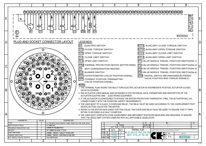
HT ANTI-CONDENSATION HEATER
IP3 VALVE MIDDLE TRAVEL POSITION SWITCH(No 3)
3 22
45Leabharlann 10232 14 36 07 13 35
BLK BLINKER SWITCH POT POTENTIOMETER (VALVE POSITION SIGNAL) CPT CURRENT POSITION TRANSMITTER
MADE BY 10/03/2020 JB WD CK-CKR STD., MSM-CCW, 3PH,
CHECKED 10/03/2020 JP
NOCPT, HT115, LIM, TOR, IMP
APPROVED 10/03/2020 JP
range
FORMAT
DRAWING Nº
A4 N00300AX - 2
BLK 24-25
BLK 24-25
BE CONNECTED THROUGH BOTH CIRCUITS. STANDARD 250AVC/5A, 24VDC 0,25A. GOLD CONTACT SWITCHE (LOW ENERG. CIRCUITS) UNDER REQUEST
5
6
7
8
CK-WD
1
2
3
4
5
6
7
E D C
S1 POWER
U V W N PE
F1 F2 F3
KM2
L1 L2 L3
III ELECTRIC ACTUATOR M1
(centork supply)
V (250 VAC max allowable voltage) 0
富士变频器说明书VP_1泵控制系统说明书 免费下载

VP泵控制 功能说明书VP泵控制 功能说明书使用说明书初 版 2003年 12第2版 2004年7富士电机机器制御株式会社未经允许禁止将本手册内容的部分或全部进行转载和复制。
关于本手册内容,可能会由于产品改良而对规格等进行更改,恕不另行通知。
本手册内容力求准确,如发现任何疑问、错误或记载遗漏之处,请与本公司联系。
对于使用的结果,无论是否属于上项原因,本公司均不承担责任,请予以谅解。
前言在风机·泵用(二次方递减转矩负载用)变频器FRENIC-VP中,配备了控制多台泵的功能。
在本书中记载了有关泵控制功能的说明和使用上的注意事项。
请同时阅读FRENIC-VP的主体使用说明书和本书,进行正确地使用。
目录第1章 概要 (2)第2章 功能规格 (2)1) 变频器驱动的电机固定方式 (3)2) 变频器驱动的电机循环方式 (4)3) 输出端子的分配 (5)第3章 功能代码 (5)1) 功能代码一览 (5)2) 功能代码的说明 (7)第4章 PID设置相应功能代码说明 (16)1d)不能使用PID控制的低水量停止功能。
e)泵控制有效时,把自由旋转指令『BX』作为使变频器驱动和工频电源驱动的所有电机(泵)停止(断路)的功能来使用。
当设定为即使切断运行指令,工频电源驱动仍然继续时,建议准备『BX』输入。
15第四章PID设置相应功能代码说明1、固定方式162、循环方式17目标值(指令值)控制对象控制量驱动部分反馈值■动作选择(J01)选择PID控制的动作。
J01数据功能0 不动作1 过程控制(正动作)2 过程控制(反动作)反馈端子【12】输入J02)控制指令值的方法。
功能/ 键,通过显示系数(E40、E41)可以以转换为易于识别的显示值,对处理指令的进行设定。
(端子【12】、【C1】、【V2】)的设定以外,各模拟设定(功能代码E61、E62、E63)也需要选择PIDE61、E62、E63。
指令』及DOWN指令『DOWN』,通过显示系数(E40、E41)可以转换为易于识别的显示值,~100%进行设定。
VP500-TF2Z534EN系列残压释放式阀门说明书
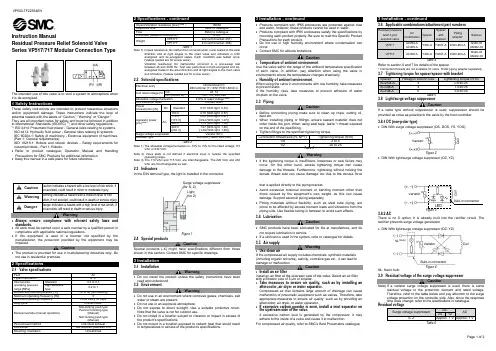
Instruction ManualResidual Pressure Relief Solenoid ValveSeries VP517/717 Modular Connection TypeThe intended use of this valve is to vent a system to atmosphere whenit is de-energised.1 Safety InstructionsThese safety instructions are intended to prevent hazardous situationsand/or equipment damage. These instructions indicate the level ofpotential hazard with the labels of “Caution,” “Warning” or “Danger.”They are all important notes for safety and must be followed in additionto International Standards (ISO/IEC)*1), and other safety regulations.*1)ISO 4414: Pneumatic fluid power - General rules relating to systems.ISO 4413: Hydraulic fluid power - General rules relating to systems.IEC 60204-1: Safety of machinery - Electrical equipment of machines.(Part 1: General requirements)ISO 10218-1: Robots and robotic devices - Safety requirements forindustrial robots - Part 1: Robots.•Refer to product catalogue, Operation Manual and HandlingPrecautions for SMC Products for additional information.• Keep this manual in a safe place for future reference.Caution Caution indicates a hazard with a low level of risk which, ifnot avoided, could result in minor or moderate injury.Warning Warning indicates a hazard with a medium level of riskwhich, if not avoided, could result in death or serious injury.Danger Danger indicates a hazard with a high level of risk which, ifnot avoided, will result in death or serious injury.Warning•Always ensure compliance with relevant safety laws andstandards.•All work must be carried out in a safe manner by a qualified person incompliance with applicable national regulations.•If this equipment is used in a manner not specified by themanufacturer, the protection provided by the equipment may beimpaired.Caution•The product is provided for use in manufacturing industries only. Donot use in residential premises.2 Specifications2.1 Valve specificationsFluid AirType of actuation N. C.Internal pilotoperating pressurerange [MPa]Standard 0.2 to 0.7High pressuretype0.2 to 1Ambien and fluid temperature [˚C]-10 to 50 (No freezing)Maximum operating frequency [Hz] 5Minimum operating frequency Once every 30 daysDuty cycle Contact SMCManual override (manual operation)Non-locking push typePush-turn locking type(Manual)Non-locking push type(Manual)Pilot exhaust method Individual exhaustLubrication Not required (See also 3.4)Mounting orientation Unrestricted2 Specifications - continuedImpact/Vibration resistance [m/s2] Note 1150/30Response time Refer to catalogueFlow Refer to catalogueEnclosure (based on IEC60529) IP65WeightVP517Y 222 (with bracket: 257)VP717Y 413 (with bracket: 468)Table 1Note 1) Impact resistance: No malfunction occurred when it was tested in the axialdirection and at right angles to the main valve and armature in bothenergized and de-energized states. Each condition was tested once.(Values quoted are for a new valve).Vibration resistance: No malfunction occurred in a one-sweep testbetween 45 and 2000 Hz. Test was performed in both energized and de-energized states in the axial direction and at right angles to the main valveand armature. (Values quoted are for a new valve).2.2 Solenoid specificationsElectrical entryDIN terminal (D)DIN terminal (Y) <EN175301-803(C)>Coil rated voltage [V]DC 24, 12AC (50/60 Hz) 100, 110, 200, 220Allowable voltage fluctuation ±10% of rated voltage Note 1, 2Coil insulation class Contact SMCPowerconsumption [W]DC Standard 0.35 (With light: 0.45)Apparent power[VA] Note 3AC100 V 0.78 (With light: 0.87)110 V[115 V]0.86 (With light: 0.97)[0.94 (With light: 1.07)]200 V 1.15 (With light: 1.30)220 V[230 V]1.27 (With light: 1.46)[1.39 (With light: 1.60)]Surge voltage suppressor Varistor (DC)Indicator light LED (DC), Neon bulb (AC)Table 2Note 1) The allowable voltage fluctuation is -15% to +5% for the rated voltage 115VAC or 230 VAC.Note 2) Valve state is not defined if electrical input is outside the specifiedoperating range.Note 3) The 110 VAC and 115 VAC are interchangeable. The 220 VAC and 230VAC are interchangeable as well.2.3 IndicatorsIn the DIN terminal type, the light is installed in the connector.Figure 12.4 Special productsCautionSpecial products (-X) might have specifications different from thoseshown in this section. Contact SMC for specific drawings.3 Installation3.1 InstallationWarning•Do not install the product unless the safety instructions have beenread and understood.3.2 EnvironmentWarning•Do not use in an environment where corrosive gases, chemicals, saltwater or steam are present.•Do not use in an explosive atmosphere.•Do not expose to direct sunlight. Use a suitable protective cover.Note that the valve is not for outdoor use.•Do not install in a location subject to vibration or impact in excess ofthe product’s specifications.•Do not mount in a location exposed to radiant heat that would resultin temperatures in excess of the product’s specifications.3 Installation - continued•Products compliant with IP65 enclosures are protected against dustand water, however, these products cannot be used in water.•Products compliant with IP65 enclosures satisfy the specifications bymounting each product properly. Be sure to read the Specific ProductPrecautions for each product.•Do not use in high humidity environment where condensation canoccur.•Contact SMC for altitude limitations.Caution•Temperature of ambient environmentUse the valve within the range of the ambient temperature specificationof each valve. In addition, pay attention when using the valve inenvironments where the temperature changes drastically.•Humidity of ambient environmentWhen using the valve in environments with low humidity, take measuresto prevent static.If the humidity rises, take measures to prevent adhesion of waterdroplets on the valve.3.3 PipingCaution•Before connecting piping make sure to clean up chips, cutting oil,dust etc.•When installing piping or fittings, ensure sealant material does notenter inside the port. When using seal tape, leave 1 thread exposedon the end of the pipe/fitting.•Tighten fittings to the specified tightening torque.Connection thread size (R, NPT) Tightening torque (N∙m)1/8 3 to 51/2 20 to 25Table 3Warning•If the tightening torque is insufficient, looseness or seal failure mayoccur. On the other hand, excess tightening torque can causedamage to the threads. Furthermore, tightening without holding thefemale thread side can cause damage too due to the excess forcethat is applied directly to the piping bracket.•Avoid excessive torsional moment or bending moment other thanthose caused by the equipment’s own weight, as this can causedamage. Support external piping separately.•Piping materials without flexibility, such as steel tube piping, areprone to be affected by excess moment loads and vibrations from thepiping side. Use flexible tubing in between to avoid such effects.3.4 LubricationCaution•SMC products have been lubricated for life at manufacture, and donot require lubrication in service.•If a lubricant is used in the system, refer to catalogue for details.3.5 Air supplyWarning•Use clean airIf the compressed air supply includes chemicals, synthetic materials(including organic solvents), salinity, corrosive gas etc., it can lead todamage or malfunction.Caution•Install an air filterInstall an air filter at the upstream side of the valve. Select an air filterwith a filtration size of 5 µm or smaller.•Take measures to ensure air quality, such as by installing anaftercooler, air dryer or water separator.Compressed air that contains large amount of drainage can causemalfunction of pneumatic equipment such as valves. Therefore, takeappropriate measures to ensure air quality, such as by providing anaftercooler, air dryer, or water separator.•If excessive carbon powder is seen, install a mist separator onthe upstream side of the valve.If excessive carbon dust is generated by the compressor, it mayadhere to the inside of a valve and cause it to malfunction.For compressed air quality, refer to SMC’s Best Pneumatics catalog ue.3 Installation - continued3.6 Applicable combinations/attachment part numbersResidual pressurerelief 3 portsolenoid valveAircombinationSpacerSpacerwithbracketPipingadapter*SilencerVP517AC25#-AAC30#-AY300-A Y300T-A E300-#03-AAN30-03AN302-03VP717 AC40#-A Y400-A Y400T-A E400-#04-AAN40-04AN402-04Table 4Refer to section 6 and 7 for details of the spacer.* Connection threads are not available for valve. Order piping adapter separately.3.7 Tightening torque for spacer/spacer with bracketSpacer Hexagon wrench size Tightening torque (N∙m)AC25-#-A 3 0.6±0.05AC30#-A 4 1.5±0.05AC40#-A 5 3.0±0.05Table 53.8 Light/surge voltage suppressorCautionIf a valve type without suppression is used, suppression should beprovided as close as possible to the valve by the host controller.3.8.1 DC (non-polar type)•DIN With surge voltage suppressor (DS, DOS, YS, YOS)Figure 2•DIN With light/surge voltage suppressor (DZ, YZ)Figure 33.8.2 ACThere is no S option. It is already built into the rectifier circuit. Therectifier prevents surge voltage generation.•DIN With light/surge voltage suppressor (DZ, YZ)Figure 4NL: Neon bulb3.9 Residual voltage of the surge voltage suppressorCautionNote) If a varistor surge voltage suppressor is used, there is someresidual voltage to the protection element and rated voltage.Therefore, refer to the table below and pay attention to the surgevoltage protection on the controller side. Also, since the responsetime does change; refer to the specifications in catalogue.Residual voltageSurge voltage suppressorDCAC24 12S, Z Approx. 1 V Approx. 1 VTable 6Varistor CoilNL Note)Built-in connectorCoilVaristorSurge voltage suppressor(for S, Z)Light(for Z) Varistor CoilBuilt-in connector3 Installation - continued3.10 Countermeasure for surge voltageCautionAt times of sudden interruption of the power supply, the energy stored in a large inductive device may cause non-polar type valves in a de-energised state to switch.When installing a breaker circuit to isolate the power, consider a valve with polarity (with polarity protection diode), or install a surge absorption diode across the output of the breaker.3.11 Extended periods of continuous energizationCaution• Refer to ‘3, 4, 5 port solenoid valves precautions’ for more details. • When solenoid valves are mounted in a control panel, employ measures to radiate excess heat, so that temperatures remain within the valve specification range. 3.12 WiringWarning• The solenoid valve is an electrical product. For safety, install an appropriate fuse and circuit breaker before use.Caution• External force applied to lead wireIf an excessive force is applied to the lead wire, this may cause faulty wiring. Take appropriate measures so that a force of 30 N or more is not applied to the lead wire. When instructions are given to the Specific Product Precautions, follow these specifications. 3.13 How to use DIN terminalCautionThe DIN terminal type with an IP65 enclosure is protected against dust and water, however, it must not be used in water.Connection 1. L oosen the holding screw and pull the connector out of the solenoid valve terminal block. 2. A fter removing the holding screw, insert a flat head screwdriver, etc. into the notch on the bottom of the terminal block and pry it open, separating the terminal block and the housing. 3. L oosen the terminal screws (slotted screws) in the terminal block. Insert the lead core wires into the terminals according to the connection method, and secure the wires by re-tightening the terminal screws. 4. S ecure the cord by fastening the ground nut.CautionWhen making connections, please note that using a heavy-duty cord of a size outside of the range of supported sizes (ø3.5 mm to ø7 mm) will not satisfy IP65 (enclosure) standards. Also, be sure to tighten the gland nut and holding screw within their specified torque ranges. Changing the entry directionAfter separating terminal block and housing, the cord entry direction can be changed by attaching the housing in the desired different direction (four directions at 90˚ int ervals).* When equipped with a light, be careful not to damage the light with the cord’s lead wires .PrecautionsPlug in and pull out the connector vertically without tilting to one side. Applicable cableCable O.D.: Ø3.5 mm to Ø7 mm(Reference) 0.5 mm 2, 2-core or 3-core, equivalent to JIS C 33063 Installation - continuedFigure 53.14 DIN Terminal conforming to EN175301-803C (former DIN 43650C)Y type DIN terminal corresponds to the DIN connector with terminal pitch 8 mm, which complies with EN175301-803C. Since the terminal pitch is different from the D type DIN connector (which has a pitch of 9.4 mm), these two types are not interchangeable.Y type D typeFigure 6Applicable cableCable O.D.: Ø3.5 mm to Ø7 mm(Reference) 0.5 mm 2, 2-core or 3-core, equivalent to JIS C 3306 Refer to 3.13 for connection and change of entry direction details. 3.15 Circuit with indicator light (built-in connector)DC (Z) circuit AC (Z) circuitFigure 7Figure 8LED: Light emitting diode NL: Neon lightR: ResistorR: ResistorFigure 73.16 Solenoid valve for AC specificationWarningAC specification pilot valves have a built-in rectifier that generates heat when energized.The surfacemaybecomehot dependingon theenergized condition; therefore, do not touch the solenoid valves.3.17 Manual overrideWarningRegardless ofan electric signal for the valve, the manual override is used for switching the main valve. Since connected equipment will operate when the manual override is activated, confirm that conditions are safe prior to activation.Locked manual overrides might prevent the valve responding to being electrically de-energised or cause unexpected movement in the equipment.Type AType ERefer to catalogue for additional details.4 How to OrderRefer to catalogue for ‘How to Order’.5 Outline DimensionsRefer to catalogue for outline dimensions.Refer to catalogue also for spacer, bracket, piping adaptor and silencer dimensions.6 Maintenance6.1 General maintenanceCaution• Not following proper maintenance procedures could cause the product to malfunction and lead to equipment damage.• Ensure sufficient space for maintenance and inspection. Refer to section 5 for the minimum clearance of each component. • If handled improperly, compressed air can be dangerous.• Maintenance of pneumatic systems should be performed only by qualified personnel.• Before performing maintenance, turn off the power supply and be sure to cut off the supply pressure. Confirm that the air is released to atmosphere.• After installation and maintenance, apply operating pressure and power to the equipment and perform appropriate functional and leakage tests to make sure the equipment is installed correctly.• If any electrical connections are disturbed during maintenance, ensure they are reconnected correctly and safety checks are carried out as required to ensure continued compliance with applicable national regulations.• Do not make any modification to the product.• Do not disassemble the product, unless required by installation or maintenance instructions.• Ensure seals are in good condition, not deformed and are dust and debris free.• When mounting valves ensure seals are present, aligned and securely in place and tighten screws to a torque as per section 3.7. 6.2 AccessoriesRefer to Specific Product Catalogue for more details.6.2.1 SpacerY300-A or Y400-A.Figure 8: Y400-A6.2.2 Spacer with bracket Y300T-A or Y400T-A.Figure 9: Y400T-A6.2.3 Piping adapter 3/8”, 1/2”A piping adapter allows installation/removal of the component without removing the piping and thus makes maintenance easier.Figure 10: E300-#03-A or E400-#04-A6 Maintenance - continued6.2.4 Silencer 3/8”, 1/2”Figure 11: AN30-03/AN40-04Figure 12:AN302-03/AN402-047 Limitations of UseWarningSystem designer should determine the effect of the possible failure modes of the product on the system.7.1 Limited warranty and disclaimer/compliance requirements Refer to Handling Precautions for SMC Products.Warning7.2 Holding of pressureSince valves are subject to air leakage, they cannot be used for applications such as holding pressure (including vacuum) in a system. 7.3 Cannot be used as an emergency shut-off valveThis product is not designed for safety applications such as an emergency shut-off valve. If the valves are used in this type of system, other reliable safety assurance measures should be adopted.7.4 Safety relays or PLCIf a safe output from a safety relay or PLC is used to operate this valve, ensure that any output test pulse duration is shorter than 1 ms to avoid the valve solenoid responding.7.5 Air/spring returned spool valves 7.5.1 Internal pilot typeFor internal pilot type, the main valve returns to the original (de-energized) position by means of the spring when the air supply is cut.When only the electrical power is cut, the return is by means of the pilot pressure and spring force.Caution7.6 Low temperature operationUnless otherwise indicated in the specifications for each valve, operation is possible to -10 °C, but appropriate measures should be taken to avoid solidification or freezing of drainage and moisture, etc.7.7 Air connectionTo avoid reversed connections of the air inlet/outlet, make connections aft er confirming the “IN/OUT” marks or arrows that indicate the direction of air flow. Reversed connections can cause malfunction. 7.8 Leakage voltageCautionEnsure that any leakage current when the switching element is OFF causes ≤3% of the rated voltage across the valve for DC coil and ≤8% for AC coils.8 Product DisposalThis product shall not be disposed of as municipal waste. Check yourlocal regulations and guidelines to dispose this product correctly, in order to reduce the impact on human health and the environment.9 ContactsRefer to or www.smc.eu for your local distributor/importer.URL : https:// (Global) https:// www.smc.eu (Europe) SMC Corporation, 4-14-1, Sotokanda, Chiyoda-ku, Tokyo 101-0021, JapanSpecifications are subject to change without prior notice from the manufacturer. ©2022 SMC Corporation All Rights Reserved. Template DKP50047-F-085HGround nut Tightening torque 1.65 to 2.5 N ∙mWasherGrommet (Rubber) (Voltage symbol)Terminal block Notch(Location for light mounting) HousingHolding screw Tightening torque 0.3 to 0.4 N ∙m Terminal screw (3 locations) Tightening torque 0.2 to 0.25N ∙m49 (VP517), 67 (VP717)48.9 (VP517), 66.9 (VP717) 1 (+)2 (-) 1 (+)Ground Ground2 (-)。
阀门定位器.模块使用说明书

阀门定位器.模块使用说明书ZXQ 系列电动阀门智能定位器/阀门操作器(电子式伺服控制器)使用说明书DOC NO :201109ZXQ20 ZXQ20ZXQ20ZXQ20目录1一、概述 (2)二、主要技术指标 (2)三、定位器面板 (3)四、接线方式 (5)五、设定操作方法 (6)六、错误代码列表 (9)附录:其它标定操作(出厂后如需此项操作,请在厂家指导下使用) (9)如顾客所购买的是本公司Z型(机电一体)执行器,内部定位器无需对执行器转角标定,接线无误即可正常使用。
系列电动阀门智能定位器是以工业单片机为核心的智能信号采集控制系统,体积小巧,可选择安装在电动执行器的接线盒内或以DIN导轨方式固定在外,能直接接收工业仪表或计算机等输出的4~20mA DC信号(其它输入信号类型可在出厂前定制),与电位器反馈的电动执行器配套对各种阀门或装置进行精确定位操作,能对电动执行器的转角(或位移)进行自由标定,同时输出4~20mA DC的执行器转角位置(或位移)反馈转换信号,可精确设定执行器转角位置的下限限位值和上限限位值,定位器采用3个按键操作,9个LED灯可直接显示定位器模态,4位数码LED通过2按键切换显示阀位实际开度值、阀位设定开度值、定位器壳内温度,操作方便。
通过U4参数可调) ●可接电动执行器反馈信号:电位器500Ω~10KΩ●可接收外部控制信号(DC):4~20mA (1~5V、0~10V、开关量等出厂前定制)●输入阻抗:250Ω;●通过修改U1参数可设定:①DRTA/正动作,RVSA/逆动作模态②输入信号中断时“中断”模态—OPEN(开)、STOP(停)、SHUT(闭)●可选:可控硅输出(AC,1000V,25A)●输出执行器位置信号:低漂移输出4~20mADC对应执行器全闭至全开,信号完全与输入隔离(光电隔离),输出负载≤500Ω●环境温度:0~80℃,相对湿度:≤90%RH ●有超温保护功能: 定位器壳内温度≥70℃时,定位器停止对执行器的开闭控制●外形尺寸:ZXQ2003→77mm(底面长)×76mm(底面宽)×51mm(高/厚);ZXQ2004→74 mm(底面长)×57mm(底面宽)×45mm(高/厚)ZXQ2004B→119mm(底面长)×76mm(底面宽)×26mm(高/厚)ZXQ2004C→62mm(底面长)×48mm(底面宽)×26mm(高/厚)●可通过按键自由标定输入信号所对应执行器的动作区间(一般标定为电动执行器全闭、全开位置)●可设定最大阀位限制值与最小阀位限制值●密码锁,防止误操作●防执行器频繁启动功能●带故障报警代码指示功能(E-0X)3按输入信号和执行器转角位置进行智能步距调整精确定位■1■5■壳上的接线图连接好电动执行器和电源连线,注意连接时的极性,为减少电机干扰,应将电动执行器的电机控制线和反馈信号线分开走线;定位器的弱电信号线应尽量短些,若必须使用较长的连线时,应采用屏蔽信号线,外屏蔽与控制柜外壳妥善接地。
泳池阀门执行器 安装和操作手册说明书

Jandy ®Pro Series Valve ActuatorModel JVA 2444H 0570800 R e v JINSTALLATION ANDOPERATION MANUALEQUIPMENT INFORMATION RECORD DATE OF INSTALLATIONINSTALLER INFORMATIONINITIAL PRESSURE GAUGE READING (WITH CLEAN FILTER)PUMP MODEL HORSEPOWER FILTER MODEL SERIAL NUMBER CONTROL PANEL MODEL SERIAL NUMBER NOTES:Table of ContentsSection 1. Safety Information (4)Section 2. General Information (5)2.1 Introduction (5)2.2 Description (5)Section 3. JVA Mounting Positions (5)3.1 Standard JVA Position (5)3.2 Actuator Mounting (6)Section 4. Synchronization (7)4.1 Synchronization Methods (7)4.2 Resetting the Cams (7)Section 5. Manual Operation (9)5.1 Manual Override (9)5.2 Manual Override, Power On (9)5.3 Manual Override, Power Off (9)Section 6. Maintenance (10)6.1 Actuator (10)6.2 Valve .................................................................10Section 7. Wiring Diagrams (11)7.1 JVA Wiring Schematic 2444 (11)7.2 JVA's with Toggle Switch (11)7.3 JVA's with Time Clock (11)Section 8. Troubleshooting (12)8.1 Troubleshooting (12)Section 9. JVA Exploded Viewand Spare Parts ............................13Section 1. Safety InformationIMPORTANT SAFETY INSTRUCTIONS PERTAINING TO A RISK OF FIRE,ELECTRIC SHOCK, OR INJURY TO PERSONSREAD AND FOLLOW ALL INSTRUCTIONSWhen installing and using this electrical equipment, basic safety precautions should always be followed, including the following:SAVE THESE INSTRUCTIONSSection 2. General Information2.1 IntroductionThis manual contains information for the proper installation and operation of Jandy ® Pro Series Valve Actuators (JV A). Procedures in this manual must be followed exactly. To obtain additional copies of this manual visit . For address information, see back cover.2.2 DescriptionValve Actuators are designed to meet the needs of today's more advanced, automatic pool equipment. These fully adjustable actuators offer versatile pool/spa automation with easy setups. All actuators work with AquaLink ® RS Control Systems and are available in 24volt units.Figure 2. Standard JVA MountingSection 3. JVA MountingPositions3.1Standard JVA PositionStandard Plumbing position is with the middle port (B) as the incoming or common port to the valve (see Figure 1).Standard Mounting position is with the main body of the actuator over port B (see Figure 2).NOTE If the valve(s) are plumbed with port B as thecommon port (Standard Plumbing) and the main body of the actuator(s) are mounted over port B (Standard Mounting), there is no need to adjust the actuator cams.3.2Actuator MountingJV A’s mount directly on all full-size Jandy ProSeries Valves (8 screws on lid). Zodiac recommends motorizing Jandy Pro Series Never Lube ® Valves only. JV A’s may be mounted onto valves in any of the four (4) positions in Figure 3.1.Unscrew the locking knob by turning the knob counterclockwise. Remove the locking knob and valve handle (see Figure 4).2.For standard valves, remove the four (4) large Phillips head screws from the valve. The location of the screws you remove will determine how the actuator will be mounted (see Figure 4). When installing the large 3" valve, it is not necessary to remove any screws. Use the four mounting bosses provided.Figure 4. Remove Locking Knob and Lid Screws3.Turn the actuator over so you can see into the clear actuator shaft. There are four (4) "teeth" on the inside of the shaft. Locate the smallest "tooth" and align this "tooth" with the smallest slot on the valve (see Figure 5).Figure 5. Actuator Mounting4. Place the actuator onto the valve.5.Rotate the actuator while keeping the two shafts engaged until the screw holes on the actuator legs align with the empty screw holes (from step 2) in the valve (see Figure 6).6.Use the four (4) large 2" Phillips head screws (included with the JV A) to secure the JV A to the valve.7.Put the valve handle on the actuator shaft. Put the knob on the shaft and tighten (finger tighten only).Figure 6. Actuator MountingFigure 8. JVA Synchronization, Toggle4.2 Resetting the CamsNOTE Before resetting cams, if the valve is plumbed inStandard Plumbing position and the actuator is in Standard Mounting position there is no need for resetting the cams (see Figure 9). If a port other than "B " is plumbed as the common port or if the actuator is mounted other than Standard Mounting , the cam setting must be changed so the actuator shaft and the valve diverter rotate properly. Refer to the Cam Setting Chart on page 8 for proper settings.Figure 9. JVA Mounting Positions.1.Turn OFF actuator power. Unscrew the locking knob by turning the knobcounterclockwise. Remove the locking knob and valve handle.2.Remove the four (4) Phillips head screws that secure the actuator lid and then remove the lid.Section 4. Synchronization4.1Synchronization MethodsIf the valve is plumbed in theStandard Plumbing position and the actuator is mounted in StandardMounting position, you do not have to change the cam settings from the factory settings. However, you may have to synchronize the cams.One of the following will occur when the actuator is out of synchronization:• the actuator will rotate in the wrong direction in relation to its controller (as in a solar heating system)• one actuator will rotate incorrectly in relation to another actuator (as in pool/spa combination) Figure 7 illustrates an example of the valves and actuators of a pool/spa combination that are out ofsynchronization. The valve on the left of the illustration (suction) is plumbed with the spa line on the left side of the valve and the pool line on the right; whereas, the valve on the right of the illustration (return) is plumbed with the pool on the left side of the valve and the spa on the right. In this configuration, if the actuators are activated, one will turn to spa while the other will turn to pool. The actuators will have to be synchronized.Figure 7. JVA Synchronization, ExampleOn the actuator that is out of synchronization, flip the toggle switch located on the bottom of the actuator to the ON 2 position (see Figure 8). The toggle positions are marked on the actuator top cover. Retry the system.NOTE The cam is marked with the arrow at "0", a long hashmark at the 180° position, and 2 short hash marks at the 90° and 270° positions.4.To set the cams, rotate the cam(s) until the arrow mark on the cam(s) align with the microswitch actuator (see Figure 11).NOTE The upper cam stops counterclockwise rotation andthe lower cam stops clockwise rotation.5.Turn power ON to the actuator and use the toggle switch located on the bottom of the actuator to check rotation. Move the toggle switch to either ON 1 or ON 2. Allow the actuator shaft to move until it stops. Check valve diverter position*, if the position is correct flip the toggle switch in the opposite direction and allow the shaft to stop again. If the stop positions are correct, go to step 6. If they are not, reset the cams until correct.NOTE If the actuator does not move in either direction, referto Section 6, Troubleshooting .6.Replace the lid and tighten screws. Replace the handle and locking knob.NOTE The end of the handle which has the word OFFembossed on it exactly duplicates the shape of the valve diverter. When the handle is placed on a valve or actuator shaft the word OFF will be directly over the center of the valve diverter.Cam Setting ChartNOTE Before resetting cams, always rotate the actuator shaft so the arrow mark on each cam aligns with the pointer above its3.Important - Rotate the actuator shaft so the arrow mark on the top cam aligns with the microswitch actuator (bottom cam arrow mark should also align with the bottom microswitch actuator, see Figure 10). Locate the mounting position for the actuator (as per Figure 9, the mounting position will be either I, II, III, or IV). Next, determine what valve port is the common or inlet port (as per Figure 9, the common port will be either A, B, or C). Then refer to the Cam Setting Chart below to determine what the cam settings should be. For example, if the actuator is in JV A mounting position "I ", and the common port on the valve is port "A ", the cam settings would be 90° for the top cam and 180° for the bottom.Figure 10. JVA CamsFigure 11. JVA Cam AdjustmentSection 5. Manual Operation5.1 Manual OverrideIt is sometimes necessary to rotate valve(s) manually, without using the system controller. This occurs when the controller is not accessible/operational or when the spa or pool/spa combination require filling or draining. There are two (2) methods of manually rotating theJV A; one with power on (system operational) and one with power off (no power to the control system).5.2 Manual Override, Power On1. Move the toggle switch located on the bottomof the actuator to the opposite position (ON 1switch to ON 2 or vice versa). This will rotatethe motor to the opposite position.2. Return the toggle switch to the original positionafter use.Figure 12. JVA Synchronization, Toggle 5.3 Manual Override, Power Off1. Move toggle switch located on the bottom ofactuator to the OFF (center) position.2. Unscrew (counterclockwise) the locking knobabove the handle four (4) full turns.3. Push down on the locking knob (not thehandle). This will disengage the gear train andallow the handle, and thus the valve diverter, tobe moved to any position.4. To return the actuator to automatic position, pullup on the handle while turning it clockwise orcounterclockwise until you feel the shaft slideup into the gear train. Turn the locking knobdown (clockwise) until snug.5. Put toggle switch back to the original position.Section 6. Maintenance6.1 ActuatorThe JV A has three (3) seals which should be lubricated once a year. One o-ring is located on the bottom of the actuator where the plastic shaft exits the housing and two (2) O-rings located in the top cover near where the shaft exits the top of the housing. Use the following steps to lubricate the seals:1. Turn OFF power to the actuator.2.Remove the locking knob and handle (see Figure 13).Figure 13. JVA Shaft Seal3.Spread a small amount of Jandy Pro Series Lube or other silicone base lubricant around the actuator shaft just above the lock out ring (see Figure 13).4. Reinstall handle and locking knob. Only tighten knob one (1) turn.5. Push down on the locking knob to force the actuator shaft into manual.6.Wipe a small amount of lubricant around the actuator shaft where it protrudes from the bottom of the actuator.7. Turn handle once around to spread the lubricant.8.Pull up on the handle and tighten locking knob.6.2 ValveNOTE This section does not apply to Jandy Pro SeriesNever Lube ® Valves and non-positive seal valves. Never Lube Valves and non-positive seal valves can be identified by the absence of a grease cap. Never Lube Valves can also be identified by the name "Never Lube" on the handle.Since the actuator rotates the valve diverter whichredirects the flow of water, it is imperative that the seals and the O-rings within the valve body be lubricated often (at least every three (3) months ). Use thefollowing procedure to lubricate the valve diverter seals:1. Turn off all pool/spa equipment.2. Rotate valve handle so the OFF on the handle is over the word GREASE on the valve body.3. Unscrew (counterclockwise) and remove the black cap of the grease fitting.4.Fill cap with lubricant (Jandy Lube).5.Replace cap on fitting and turn in (clockwise) until all of the lubricant has been forced into the valve.6.Use manual operation to move the handle from side to side to spread the lubricant across the seal.7.Reset the valve handle to its original position and start the equipment.Once a year the valve should be disassembled and the O-ring and valve body inspected for damage. Thoroughly lubricate the square seal and the O-ring. Reassemble the valve.Section 7. Wiring Diagrams 7.1 JVA Wiring Schematic 24447.2 JVA's with Toggle SwitchThis diagram is for two (2) JV A 2444s.To operate more JV A's, additional poles and a higher amperage fuse are needed. Do not double lug the JV A switch leg wires (red and white wires).* Transformer must be sized for the number of JV A's. Each JV A requires .75 amp. at 24 V AC.7.3 JVA's with Time ClockThis diagram is for a single JV A 2444.To operate more JV A's, additional poles and a higher amperage fuse are needed. Do not double lug the JV A switch leg wires (red and white wires).* Transformer must be sized for the number of JV A's. Each JV A requires .75 amp. at 24 V AC.Section 8. Troubleshooting8.1 TroubleshootingAll major components, including the power cord, are replaceable without replacing the entire actuator. Each item may be replaced as a separate piece allowing easy infield repair. See Section 8, Exploded Views and Replacement Kits , for actuator replacement part numbers.ProblemCauseSolution/CheckActuator handle oscillates.Lack of valve seal lubrication.Obstruction in valve body.Lubricate valve.Remove actuator and valve lid and inspect.Actuator motor works but the valve diverter does not turn.NOTE On a pool/spa combination,the problem would be spa draining or overflowing.A). Actuator shaft broken.B). Valve diverter broken.C). Actuator in manual position.D). Gear train damaged.A). Replace actuator shaft. Refer toShaft Replacement Kit instructions for disassembly.B). Replace valve diverter.C). Pull up on the handle whilerotating counterclockwise.D). Refer to Gear Replacement Kitinstructions for disassembly.Actuator motor does not turn.A) No power to the actuator.B) Toggle switch in OFF position.C) Motor has failed.D) Failed or broken microswitch.E) Both cams in contact with their microswitches.A) Check voltage between black (common) wire and each switch leg (red then white)B) Move toggle switch to ON 1 or ON 2 position.C) Replace motor.D) Replace microswitch.E) Check Cam Setting section.Actuator rotates in one direction but not back again.A) Broken or damaged micro- switch.B) Bad connection(s).C) Bad control relay switch.D) Broken wire.A) Replace microswitch.B) Check all connections.C) At the power source check the operation of the control relay or switch.D) Check red and white wires.Water inside valve actuator.Damaged seals.Replace top lid and grease seals.Section 9. JVA Exploded View and Spare Parts Dwg.#Kit #Description Qty.1R0409600JVA Gasket and Screw KitGasketO-ring, Screw, #14 x 2" Screw, #8 x 5/8"1 2 4 42R0411500Top Housing KitGasketO-ring Screw, #8 x 5/8" Housing, Top 1 2 4 13R0408700Center Plate KitO-ringScrew, #8 x 5/8" BridgeTop Cam (Clear) Bottom Cam (Textured) MicroswitchCenter PlateOutput Shaft, Threaded Spring, JVA 2 8 1 1 1 2 1 1 14R0411600Gear KitPrimary Gear Secondary GearLarge Pinion Gear Output Gear Housing, Bottom w/3 Pins 1 1 1 1 15R0411800Cable Kit, 20'O-ring, Strain Relief Washer, Strain Relief Cap, Strain Relief Power Cord, 20' w/3-pin Connector 1 1 1 15R0411900Cable Kit, 75'O-ring, Strain Relief Washer, Strain Relief Cap, Strain Relief Power Cord, 75' w/3-pin Connector 1 1 1 16R0441700PCB w/Toggle Switch KitPCB Sub-Assy, 24V w/PCB,w/Toggle Switch, LockWasher and Nut1 7R0408500Motor KitScrew, #8 x 5/8" Motor 24V, w/Wire and Connector 1 18R0408600Cam and Microswitch KitTop Cam (Clear) Bottom Cam (Textured) Microswitch 1121 3NOTESNOTESZodiac Group Australia. 219 Woodpark Road Smithfield, NSW AU 21641.800.688.552 | .auZodiac Pool Systems, Inc.2620 Commerce Way, Vista, CA 920811.800.822.7933 | ©2016 Zodiac Pool Systems, Inc. ZODIAC® is a registered trademark of Zodiac International, S.A.S.U., used under license. All trademarks referenced herein are the property of their respective owners.H0570800 Rev JETL LISTED CONFORMS TOUL-STD 1563 CERTIFIED TO CAN/CSA C22.2 NO.218.1。
阀位控制器

6
WEST4170/8170/6170 产品手册
表 2-1 内部参数一览表
参数名称
标志
调整范围
输入数字滤波时间 输入偏置
OFF,0.5~100 秒 满量程
比例带
0.0%~999.9%
积分时间 微分时间
1 秒~99 分 59 秒和 OFF 1 秒~99 分 59 秒
设定值上限 设定值下限
设定值~量程上限 量程下限~设定值
手动输出允许开关
0 禁止 1 允许
斜率允许开关
0 禁止 1 允许
显示方式 通讯写数据允许开关 3
12345 0 只读 1 读/写
密码值
0~9999
所有操作模式下的参数均可在设置模式下显示
7
出厂值
2秒 0
10% 5分0秒
0秒 量程上限 量程下限 量程上限 量程下限
1分
1秒 量程上限 量程下限
5 5 量程上限 量程下限 5 5 0 1 1000 0 0 0 0 1 1 10
12
WEST4170/8170/6170 产品手册
三类指令 L {N} {P} #{DATA}*
四类指令 L {N} {P}I *
所有字符皆为 ASCII 码 且
L
信息开始位
{N}
为控制器地址 1 32 1~9 可以
用一位或两位 如 7 和 07 皆可
{P}
为参数代码
{C}
指令
#
表示接下来为{DATA}
6170/8170/4170 阀位控制器手册
WEST4170/8170/6170 产品手册
目录
1 操作模式------------------------------------------------------------02 2 参数设置------------------------------------------------------------07 3 RS485 串行通讯---------------------------------------------------13 4 安装------------------------------------------------------------------20 5 跳线------------------------------------------------------------------23 附录 A------------------------------------------------------------------27
Valvetronic PVL-C10 G1 4 气动流量控制阀门说明说明书
•High flow, compact, light weight •Push-in or threaded pneumatic outlets•High performance 15 mm solenoid DIN 43 650 C •DIN rail or surface mounting•Electrical head connection by Cable gland, Sub D 25 or Industrial Cylindrical ConnectionValvetronicPVL-C10 G1/4Dimensions see pages 41 - 42Valvetronic PVL-C10 G1/4Ex = to collect the exhausts of the solenoids* Px = auxiliary air supply for solenoids, separately from the main valves air supply** To be mounted at the end of the island valves for dual air supply (without electrical connections)** * For dual air supply ou different supplies, with no defined location in the island valves (with connections fitted)Valvetronic PVL-C10 G1/4Valvetronic Combination of PVL-B10 and PVL-C10Main data for Combination Kits PVL-B10/PVL-C10ConnectionWeightcombination module kg PVL-B10/PVL-C10Without Px version*G 1/4 and G 3/80,530With Px version( Ø4 mm) *G 1/4 and G 3/80,535Combination bus ASI/PVL-C10Without Px version*G 3/80,305With Px version( Ø4 mm) *G 3/80,310* Px = auxiliary air supply for solenoids, separately from the main valves air supply.PVL-C2713B19PVL-C2713BASI Common ModuleCommon Electrical Head Connection PVL-B10 1/8"PVL-C10 1/4"•Total compatibility with ASI Bus •Islands from 4 to 16 valves output •Modularity of 4 Outputs •Protection level IP 65•One single connection ASI•One single connection Valve supply 24 V DCValvetronicPVL-C10 on ASI BusASI Bus Module characteristics Protection level IP 65ASI operating voltage 26,9 to 31,6 V Solenoid voltage 24 V DC ±10%Operating voltage 0 to 55 °C Vibrations IEC 68-2-6 1g Shock IEC 68-2-27 15 g 11 ms EMC Protection IEC 801-2 level 3IEC 801-3 level 3IEC 801-4 level 3Working temperature 0 °C to 55 °C Identification code8.F Mounting DIN railOperating informationASI Network characteristicsMaximum lengh100 m Maximum length with duplicator 200 mNode capacity 4 inputs and 4 outputs Total capacity 124 Inputs and 124 output Number of nods 1 to 31Response time 5 ms maxi Nodes supplyFrom the Bus Total available current2 A or 5 AMain data for ASI Bus Modules - Outputs versionDescription ConnectionWeightOrder code kg Head moduleM12 ASI and valves supply 0,460P2S-BA1BA40Intermediary air feed module-0,410P2S-BA5BA40Associating module Without Px version*G 3/80,305PVL-C1713B on ASI Bus with air supplyWith Px version G 3/80,310PVL-C2713B (Ø4 mm) *Connecting lead to the ASI module addressing terminal-0,150P8L-MH02B1* Px = auxiliary air supply for solenoids, separately from the main valves air supply.Dimensions see pages 41 - 42•Total compatibility with ASI Bus•Islands from 4 to 16 valves output and 4 to 16 inputs •Protection level IP 65•Connection M12 or Vampire plug•ASI indication and 24 V supply diagnostic by LED •Inputs indication by LEDValvetronicPVL-C10 on ASI BusASI Bus Module characteristics Protection level IP 65ASI operating voltage 26,9 to 31,6 V Solenoid voltage 24 V DC ±10%Isolation voltage 1500 V Vibrations IEC 68-2-6 1g Shock IEC 68-2-27 15 g 11 ms EMC Protection IEC 801-2 level 3IEC 801-3 level 3IEC 801-4 level 3Bus diagnostic 2 LED, red and green Solenoid voltage indication By LED Short circuit protection Diagnostic by LED Working temperature 0 °C to 55 °C Storage temperature -40 °C to 70 °C Solenoid voltage ASI Vampire plug or M12Operating informationIdentification code7.FBus connectionASI Vampire plug or M12Connector Available current on inputs 200 mACompalibility with sensors or photo-cells 2 or 3 wires technologyInputsPNP typeASI Network characteristics Maximum lengh100 m Maximum length with duplicator 200 mNode capacity 4 inputs and 4 outputs Total capacity 124 Inputs and 124 output Number of nods 1 to 31Response time 5 ms maxiNodes supplyThrough the Bus Total available current2 A or 5 A* Px = auxiliary air supply for solenoids, separately from the main valves air supply.Main data for ASI Bus Modules - Inputs and Outputs versionDescription ConnectionWeightOrder code kg Head moduleM12 ASI and valves air supply0,460PVL-BA1BA44Vampire ASI and valves air supply 0,460 PVL-BA1BA44VIntermediary air feed module -0,400PVL-BA5BA44Associating module Without Px version*G 3/80,305PVL-C1713B on ASI Bus with air supplyWith Px version G 3/80,310PVL-C2713B(Ø4 mm) *Connecting lead to the ASI module addressing terminal -0,150P8B-AJACK Spare Vampire cover clip-0,150P8B-AVMP2Sold by lot of 10Dimensions see pages 41 - 421 = 24 V DC2 = Signal 23 = 0 V DC4 = Signal 11 = A +2 = Free3 = A -4 = Free1 = 24 V DC2 = Free3 = 0 V DC4 = FreeValves supplyASIConnectionNC, Standard NO, Standard NC, High flowflowflowWorking pressure 0 to 10 bar0 to 10 bar0 to 10 barWorking temperature -15 °C to +60 °C -15 °C to +50 °C -15 °C to +50 °C Orifice diameter 1,0 mm 1,1 mm 1,4 mm Flow Qmax 33 Nl/min33 Nl/min50 Nl/minPower, Hold DC1,2 W / AC1,6 VA DC1,8 W / AC 2,4 VA DC1,8 W / AC 2,4 VA Power, Inrush 1,2 W / AC 3,5 VA 1,8 W / AC 5,5 VA 1,8 W / AC 5,5 VA Voltage range+ 10 %, -15 %+ 10 %, -15 %+ 10 %, -15 %Note! Solenoids are supplied without screws, to select and order suitable screws please refer to page : 35Operating information•High performance and flow •8 mm Pin spacing•UL Listed (according types)•IP 65 Encapsulated coil (connected)•Full compliance with European Directives 73/23/EEC "Low Voltage"89/336/EEC "Electro-Magnetic Compability"Valvetronic Solenoid valves 3/2 15 mm DIN 43 650 form CSolenoid 15 mm NC Standard flow(electrical interface same side as pneumatic interface)VoltageWeightOrder code Weight Order codeWeightOrder codekg Without manual override kg With manual override kg With manual override Non locking flush Locking flush 12 VDC 0,038P2E-KS32B00,038P2E-KS32B10,038P2E-KS32B224 VDC 0,038P2E-KS32C00,038P2E-KS32C10,038P2E-KS32C248 VDC0,038P2E-KS32D00,038P2E-KS32D10,038P2E-KS32D224 VAC 50Hz 0,038P2E-KS31C00,038P2E-KS31C10,038P2E-KS31C248 VAC 50/60Hz 0,038P2E-KS34D00,038P2E-KS34D10,038P2E-KS34D2115 VAC 50Hz/0,038P2E-KS31F00,038P2E-KS31F10,038P2E-KS31F2120 VAC 60Hz VoltageWeightOrder code Weight Order codekg With manual override kg With manual override Extended non locking Extended locking 24 VDC0,038P2E-KS32C30,038P2E-KS32C424 VAC 50Hz0,038P2E-KS31C30,038P2E-KS31C4Solenoid 15 mm NC High flow(electrical interface same side as pneumatic interface)VoltageWeightOrder code WeightOrder code WeightOrder code kg Without manual kg Override flush kg Override flush override Non locking Locking 24 VDC0,038P2E-HS32C00,038P2E-HS32C10,038P2E-HS32C224 VAC 50Hz 0,038P2E-HS31C00,038P2E-HS31C10,038P2E-HS31C248 VDC0,038P2E-HS32D00,038P2E-HS32D10,038P2E-HS32D2115 V 50Hz /0,038P2E-HS31F00,038P2E-HS31F10,038P2E-HS31F2120 V 60Hz VoltageWeightOrder codeWeightOrder codekg Override extended kg Override extended non locking locking 24 VDC0,038P2E-HS32C30,038P2E-HS32C424 VAC 50Hz 0,038P2E-HS31C30,038P2E-HS31C448 VDC0,038P2E-HS32D30,038P2E-HS32D4115 V 50Hz /0,038P2E-HS31F30,038P2E-HS31F4120 V 60HzValvetronicSolenoid valves 3/2 15 mm DIN 43 650 form CSolenoid 15 mm NO Standard flow(electrical interface same side as pneumatic interface)VoltageWeightOrder code WeightOrder code WeightOrder code kg Without manual kg Overridekg Overrideoverride Non locking flush Locking flush 24 VDC0,038P2E-KS12C00,038P2E-KS12C10,038P2E-KS12C224 VAC 50Hz0,038P2E-KS11C00,038P2E-KS11C10,038P2E-KS11C2VoltageWeightOrder codeWeightOrder codekg Override extended kg Override extended non locking locking 24 VDC0,038P2E-KS12C30,038P2E-KS12C424 VAC 50Hz0,038P2E-KS11C30,038P2E-KS11C4Main data for spare set of Solenoids Mounting screwsKitType Material Ø mm Length WeightOrder code mm kg Metric Steel, passivated M3260,02P2E-KP026PM3*Self tapping Steel, passivatedØ 3 mm250,02P2E-KP025PS3**Sold by lot of 10Correspondence table between screws and Valves SeriesValvetronic Description Mounting screw Order codeSeries length Mounting screw kit P2S-HW Valvetronic Solstar 25 mm P2E-KP025PS3P2S-EW Interface 200026 mm P2E-KP026PM3PVL-B10Valvetronic 1/8"26mm P2E-KP026PM3PVL-C10Valvetronic 1/4"26 mmP2E-KP026PM3Valvetronic Connecting LeadsValvetronic Connecting LeadsValvetronicPVL-C104,4158100584,458100158154215100158584,45664215556664256156628584227,56671666925100158464,4100581584215556661005815858100158336669Intermediary air supply moduleTransfer Module from PVL-B10/PVL-C10 and Head ASI bus / Air feed module PVL-C10Valve 5/2 monostableValve 5/2 bistable - 2x3/2 - 5/35Valvetronic PVL-C10 Association PVL-B10 G1/8 and PVL-C10 G1/4Association ASI and PVL-C10Association ASI and PVL-B10 and PVL-C10Pneumatic Service and Replacement PartsPVL-C10 Series ValvesNo internal components available, replace complete valve or solenoidReplacement Solenoids。
阀门操作、维护和使用手册说明(阀门投标专用)
阀门储存、操作、维护和使用说明概述阀门是用来关闭和开启管道中介质。
切断阀没有节流的功能。
该类阀门顺时针旋转手轮,直到完全将通道切断,阀门关闭。
逆时针旋转手轮,直到碰到阻挡,阀门打开。
对于电动装置阀门,在断电等紧急情况下,可以使用备用手轮打开和关闭阀门。
注意!截止阀在不超过10%开启状态连续节流会对阀瓣和阀座引起剧烈振动、噪音、磨损和损坏。
止回阀作为控制管道介质单向流动的元件,当介质顺流时由管线自身压力的作用开启阀门,当介质倒流时依靠阀瓣自身重量、弹簧力和介质回流的压力作用在阀瓣背部,使阀瓣与阀座形成密封,达到止回截流的目的。
警告!禁止用夹泵的方式对阀门进行泵验。
1.阀门的储存1.1发运准备阀门的包装应能防止阀门在运输过程和储存时不发生任何损坏。
并应注意以下几点:①闸阀:包装时,闸板应处于关闭状态。
②截止阀:包装时,阀瓣应处于关闭状态。
②止回阀:包装时,升降式止回阀、蝶形止回阀和对夹立式止回阀应将阀瓣有利于关闭状态摆放;旋启式止回阀和斜瓣式止回阀的阀瓣用丁字形木条顶住,丁字形木条一端撑紧在出口端孔内,以使阀瓣在运输过程中不会碰撞。
对于外接附件如阻尼缸、气缸等,应将附件可靠小心地完全固定。
1.11阀门法兰密封面/焊接坡口/螺纹端应涂合适的防护油脂(不锈钢材质除外),阀门两端应可靠地固接木质、木纤维或塑料端以防护连接端面和阀门内部。
对于闸阀和截止阀:齿轮箱或电动装置阀门包装时须小心地安全固定,以确保齿轮箱或电动装置不会损坏并不至于穿破木箱/板条箱。
1.12包装型式应在订单中明确规定,以便安全地运输至目的地和确保安装前的保存。
1.2吊运要求1.21包装完好的阀门板条箱:用叉车进行装卸。
木箱:在木箱的重心位置处设置装吊点进行装卸。
1.22已开箱的阀门①这些阀门的吊运要采取合适的手段和措施如应用货盘进行装卸,注意应避免加工面受到损坏。
②对大尺寸阀门,在吊运阀门时可用皮带或链条绕过阀体的颈部吊起,并应保持平衡以防止意外坠落或在吊运过程中松动。
阀门定位器.模块使用说明书
ZXQ系列电动阀门智能定位器/阀门操作器(电子式伺服控制器)使用说明书DOC NO:201109ZXQ2003ZXQ2004BZXQ2004ZXQ2004C目录一、概述 (2)二、主要技术指标 (2)三、定位器面板 (3)四、接线方式 (5)五、设定操作方法 (6)六、错误代码列表 (9)附录:其它标定操作(出厂后如需此项操作,请在厂家指导下使用) (9)如顾客所购买的是本公司Z型(机电一体)执行器,部定位器无需对执行器转角标定,接线无误即可正常使用。
ZXQ系列电动阀门智能定位器是以工业单片机为核心的智能信号采集控制系统,体积小巧,可选择安装在电动执行器的接线盒或以DIN导轨方式固定在外,能直接接收工业仪表或计算机等输出的4~20mA DC信号(其它输入信号类型可在出厂前定制),与电位器反馈的电动执行器配套对各种阀门或装置进行精确定位操作,能对电动执行器的转角(或位移)进行自由标定,同时输出4~20mA DC的执行器转角位置(或位移)反馈转换信号,可精确设定执行器转角位置的下限限位值和上限限位值,定位器采用3个按键操作,9个LED灯可直接显示定位器模态,4位数码LED通过按键切换显示阀位实际开度值、阀位设定开度值、定位器壳温度,操作方便。
●控制精度:0.1%~3.0%(通过U4参数可调)●可接电动执行器反馈信号:电位器500Ω~10KΩ●可接收外部控制信号(DC):4~20mA (1~5V、0~10V、开关量等出厂前定制)●输入阻抗:250Ω;●通过修改U1参数可设定:①DRTA/正动作,RVSA/逆动作模态②输入信号中断时“中断”模态—OPEN(开)、STOP(停)、SHUT(闭) ●可选:可控硅输出(AC,1000V,25A)●输出执行器位置信号:低漂移输出4~20mA DC对应执行器全闭至全开,信号完全与输入隔离(光电隔离),输出负载≤500Ω●环境温度:0~80℃,相对湿度:≤90%RH●有超温保护功能: 定位器壳温度≥70℃时,定位器停止对执行器的开闭控制●外形尺寸:ZXQ2003→77mm(底面长)×76mm(底面宽)×51mm(高/厚);ZXQ2004→74 mm(底面长)×57mm(底面宽)×45mm(高/厚)ZXQ2004B→119mm(底面长)×76mm(底面宽)×26mm(高/厚)ZXQ2004C→62mm(底面长)×48mm(底面宽)×26mm(高/厚)●可通过按键自由标定输入信号所对应执行器的动作区间(一般标定为电动执行器全闭、全开位置)●可设定最大阀位限制值与最小阀位限制值●密码锁,防止误操作●防执行器频繁启动功能●带故障报警代码指示功能(E-0X)●按输入信号和执行器转角位置进行智能步距调整精确定位■参照下图定位器接线端子和定位器外壳上的接线图连接好电动执行器和电源连线,注意连接时的极性,为减少电机干扰,应将电动执行器的电机控制线和反馈信号线分开走线;定位器的弱电信号线应尽量短些,若必须使用较长的连线时,应采用屏蔽信号线,外屏蔽与控制柜外壳妥善接地。
费斯托比例压力调节器VPPX 2说明书
Proportional-pressure regulators VPPXProportional-pressure regulators VPPXKey features – DesignInnovative Flexible Reliable Easy to install• Multi-sensor control (cascadecontrol)• Control characteristic adjustable viaFCT• Temperature compensated• High dynamic response• High repetition accuracy• Individual valves (in-line valve)• Sub-base valves(manifold/flanged valve)• Actual value input for externalsensors• Freely adjustable limit value• Possible to control many physicalvariables• Current or voltage can be setindividually using FCT• Integrated pressure sensor withseparate output• Wire break monitoring• Pressure is maintained if the controlsystem fails• LED display• Manifold block (manifold)• H-rail mounting• Individually via mounting bracket• QS fittings• Mounting bracket can be installedin increments of 180°• Compressed air supply/exhaust atboth ends2d Internet: /catalogue/...Subject to change – 2022/03Proportional-pressure regulators VPPX Key features – Control23The DUO cable makes it easy to con-nect an external sensor to the VPPX.To ensure a secure connection, thesensor and valve signals arepre-assigned.23[1] PLC[2] DUO cable NEDU[3] Sensor SFAB[4] Valve manifold assembly VPPX3 2022/03 – Subject to change d Internet: /catalogue/...4d Internet: /catalogue/...Subject to change – 2022/03Proportional-pressure regulators VPPXKey features – Control circuitDesign of a control circuitDesignMethod of operationThe figure shows a closed-loop control circuit. The reference variable w (setpoint value, e.g. 5 volts or 8 mA) initially acts on a comparator. The measuring equip -ment sends the value of the controlled variable x (actual value, e.g. 3 bar) to the comparator as a feedback signal r. The closed-loop control element detects the system deviation e and actuates the final control element. The output of the final control element acts on the controlled system. The closed-loop control element thus attempts to compensate for the difference between the reference variable w and the controlled variable x by using the final control element.This process runs continuously so changes in the reference variable are always detected. However, a system deviation will also occur if the reference variable is constant but the controlled variable changes. This happens when the flow through the valve changes in response to a switching operation, a cylinder movement or a change in load. The disturbance variable z will also cause a system deviation. An example of this is when the pressure drops in the air supply. The disturbance vari -able z acts on the controlled variable x unintentionally. In all cases, the controller is attempting to correct the controlled variable x to the reference variable w.Multi-sensor control (cascade control) of the VPPX Cascade controllerControl precisionUnlike conventional direct-acting regulators, with multi-sensor control several control circuits are nested inside each other. The overall controlled system is divided into smaller sub-sections that are easier to control for the specific task.Control accuracy and dynamic response are greatly improved with themulti-sensor control principle in comparison with a single-acting regulator.(setpoint value)ComparatorProportional-pressure regulators VPPX Key featuresIn practice there may be residual volt-age or residual current at the setpointinput of the VPPX via the setpointgenerator.Zero point suppression is used so thatthe valve is reliably exhausted at asetpoint value of zero.5 2022/03 – Subject to change d Internet: /catalogue/...Proportional-pressure regulators VPPXProduct range overview6d Internet: /catalogue/...Subject to change – 2022/03Proportional-pressure regulators VPPX Peripherals overviewIndividual valve VPPX-6L ..., VPPX-8L ...7 2022/03 – Subject to change d Internet: /catalogue/...Proportional-pressure regulators VPPXPeripherals overviewIndividual valve VPPX-12L ...8d Internet: /catalogue/...Subject to change – 2022/03Proportional-pressure regulators VPPX Peripherals overviewValve manifold assembly with VPPX-6F ..., VPPX-8F ...9 2022/03 – Subject to change d Internet: /catalogue/...Proportional-pressure regulators VPPXType codes10d Internet: /catalogue/...Subject to change – 2022/03Proportional-pressure regulators VPPX Data sheet-M-Flow rate1400 ... 7000 l/min -P- Voltage21.6 ... 26.4 V DC-L-Pressure regulation range0.02 ... 10 bar Variants• 0 ... 10 V, 0 ... 20 mA,4 ... 20 mA (can be set using FCT)• External sensor input• Actual value output can be set using FCT 0 ... 10 V, 0 ... 20 mA,4 ... 20 mA•Programming interfaceProportional-pressure regulators VPPXData sheetFlow rate qn from 1 > 2 as a function of output pressure p2Flow rate qn from 2 > 3 as a function of output pressure p2VPPX-6L/F-...-0L10H-...(10 bar)VPPX-6L/F-...-0L10H-...(10 bar)qn1-2[l/min]p 2[b a r ]2004006008001000120014001600012345678910p2[bar]q n 2-3[l /m i n ]012345678910020040060080010001200Flow rate qn from 1 > 2 as a function of output pressure p2Flow rate qn from 2 > 3 as a function of output pressure p2VPPX-8L-...-0L10H-...(10 bar)VPPX-8L-...-0L10H-...(10 bar)qn 1-2[l/min]p 2[b a r ]500100015002000250030003500012345678910p2+[bar]123456789100500100015002000250030003500Flow rate qn from 1 > 2 as a function of output pressure p2Flow rate qn from 2 > 3 as a function of output pressure p2VPPX-8F-...-0L10H-...(10 bar)VPPX-8F-...-0L10H-...(10 bar)qn 1-2[l/min]p 2[b a r ]5001000150020002500012345678910p2+[bar]1234567891005001000150020002500Flow rate qn from 1 > 2 as a function of output pressure p2Flow rate qn from 2 > 3 as a function of output pressure p2VPPX-12L-...-0L10H-...(10 bar)VPPX-12L-...-0L10H-...(10 bar)qn1-2[l/min]p 2[b a r ]200040006000800010000012345678910p2[bar]q n 2-3[l /m i n ]1234567891010002000300040005000600070008000900010000Proportional-pressure regulators VPPX Data sheet1)Supply pressure 1 should always be 1 bar greater than the maximum regulated output pressure.2)Corrosion resistance class CRC 2 to Festo standard FN 940070Moderate corrosion stress. Indoor applications in which condensation can occur. External visible parts with primarily decorative surface requirements which are in direct contact with a normal industrial environment.3)For information about the area of use, see the EC declaration of conformity at: /catalogue/... d Support/Downloads.If the devices are subject to usage restrictions in residential, commercial or light-industrial environments, further measures for the reduction of the emitted interference may be necessary.MaterialsSectional view of VPPX-6 ..., VPPX-8 ...Proportional-pressure regulators VPPXData sheetM12 – Pin allocation1 Do not connect Tx_PC2 +24 V DC supply voltage 3Analogue input W–4 Analogue input W+5 Do not connect Rx_PC 6Analogue output X7 0 V DC or GND8Input for ext. sensor signal +Proportional-pressure regulators VPPX Data sheetProportional-pressure regulators VPPX Data sheetProportional-pressure regulators VPPXAccessoriesManifold blockVABM-P1Material:Wrought aluminium alloyH- -NoteIn combination with manifold block VABM-P1- ..., sub-base valves VPPX-6F- ... and VPPX-8F- ... should be used.Proportional-pressure regulators VPPXAccessoriesCover plateVABB-P1Material:• Wrought aluminium alloy • NBR • SteelProportional-pressure regulators VPPXAccessoriesBracketVAME-P1-AMaterial:• Wrought aluminium alloy • SteelH- -NoteIn-line valves VPPX-6L- ... and VPPX-8L- ... must be used incombination with the bracket VAME-P1- A.Proportional-pressure regulators VPPXAccessoriesH-rail mountingVAME-P1-TMaterial:• Wrought aluminium alloy • SteelH- -NoteIn-line valves VPPX-6L- ... andVPPX-8L- ... must be used in combi -nation with the H-rail VAME-P1- T.Proportional-pressure regulators VPPX AccessoriesProgramming cable VAVE Materials:• Screw-type lock: Nickel-plated die-cast zinc• Housing: TPE-U(PUR), colour: black • Cable sheath: TPE-U(PUR), colour: grey• Seals: NBR•Contacts: Gold-plated brass1)For information about the area of use, see the EC declaration of conformity at: /catalogue/... d Support/Downloads.If the devices are subject to usage restrictions in residential, commercial or light-industrial environments, further measures for the reduction of the emitted interference may be necessary.21 2022/03 – Subject to change d Internet: /catalogue/...Proportional-pressure regulators VPPXAccessories22d Internet: /catalogue/...Subject to change – 2022/03Proportional-pressure regulators VPPX AccessoriesDUO cableNEDU-L1R2-V9-M12G8-E Materials:• Screw-type lock: Nickel-plated brass • Seals: FPM• Housing: TPE-U(PUR)• Cable sheath: TPE-U(PUR)• Insulating sheath: PVC•Contacts: Gold-plated brass23 2022/03 – Subject to change d Internet: /catalogue/...。