M1000E 刀片服务器速成手册
e刀片服务器

文集刀片服务器配置DELL M1000eDELL M1000E背面图全配是9个风扇,6个电源,2个CMC模块(1主2从),1个iKVM模块,6个I/O模块(A1/A2只能用于以太网交换机模块,B1/B2,C1/C2可接以太网交换机,光纤通道交换机模块)。
其前面为刀片插槽,可装半高刀片/全高刀片或混装。
前面板左下角是鼠标/键盘/显示器接口,它在选配了iKVM模块之后起作用,通过连接鼠标/键盘/显示器接口之后,利用键盘上的PrintScreen按键可访问不同刀片上的控制台(即连接到不同的刀片服务器上,输入序号1,2,… 16即可,17表示CMC控制台)。
当连接到前面板上的鼠标/键盘/显示器接口时,iKVM模块上的VGA输出会禁用。
§1.1 初始配置在系统硬件连接之后,即可进行初始配置。
最初要配置CMC系统。
需要注意的是在完成I/O模块配置之前不要打开刀片上的电源。
初始配置时仅需打开CMC控制模块上的电源按扭以启动机箱。
初始可选用超级终端连接到CMC控制模块的Console口(115200, 8 data bits, no parity, 1 stop bit, no flow control)。
以root/calvin登陆CMC系统,# getniccfg 获取当前CMC网络接口信息。
# setniccfg –# racadm racreset 激活新的网络设置。
之后即可通过IE浏览器进行配置和管理。
§1.2 配置iDRACDell PowerEdge M1000e 机箱背板上集成了iKVM以及相关的远程管理工具。
Chassis Management Controller机箱管理控制器远程访向控制器Dell ,通过每个刀片服务器上集成的CMC简称.(Remote Access Controller,iDRAC),完全可以对Dell PowerEdge M1000e中的每个刀片系统以及机箱进行远程监控和管理。
戴尔 PowerEdge M1000e 系统配置指南说明书
Dell™ PowerEdge™M1000e Systems Configuration Guide安装说明与重要信息アップデート情報정보 업데이트Dell™ PowerEdge™M1000e Systems Configuration GuideNotes, Notices, and CautionsNOTE: A NOTE indicates important information that helps you make better use of your computer.NOTICE: A NOTICE indicates either potential damage to hardware or loss of data and tells you how to avoid the problem.CAUTION: A CAUTION indicates a potential for property damage, personal injury, or death.____________________Information in this document is subject to change without notice.©2008Dell Inc.All rights reserved.Reproduction of these materials in any manner whatsoever without the written permission of Dell Inc. is strictly forbidden.Trademarks used in this text: Dell, the DELL logo, PowerEdge, and Dell OpenManage are trademarks of Dell Inc.; Microsoft, Windows, and Active Directory are either trademarks or registered trademarks of Microsoft Corporation in the United States and/or other countries.Other trademarks and trade names may be used in this document to refer to either the entities claiming the marks and names or their products. Dell Inc. disclaims any proprietary interest in trademarks and trade names other than its own.August 2008P/N R433C Rev. A00Contents1About Your System (7)System Overview (7)System Control Panel Features (10)LCD Module (11)LCD Module Menus (12)Back-Panel Features (13)Blades (13)CMC Module (16)CMC Daisy Chaining (Enclosure Stacking) (17)iKVM Switch Module (19)2Initial System Configuration (21)Before You Begin (21)Power Requirements (21)Network Information (21)Initial Setup Sequence (21)Configuring the CMC (22)Initial CMC Network Configuration (22)Logging in to the CMC Using the Web-BasedInterface (25)Adding and Managing CMC Users (26)Contents3Configuring iDRAC Networking Using theWeb-Based Interface (27)Setting the First Boot Device for Servers (28)Configuring and Managing Power (28)Installing or Updating the CMC Firmware (29)Configuring the Optional iKVM Switch Module (31)Enabling iKVM Access to the Dell CMCConsole (31)Updating the iKVM Firmware (31)Tiering the Avocent iKVM Switch From anAnalog KVM Switch (32)Tiering the Avocent iKVM Switch From aDigital KVM Switch (33)Viewing and Selecting Servers (34)FlexAddress (36)3Configuring the I/O Modules (37)Overview (37)Before You Begin (39)Network Information (39)Switch Modules (39)Configuring a Switch Module Network EthernetPort Using the Web-Based Interface (39)Cisco SFS M7000e Infiniband Switch Module (40)PowerConnect M6220 Ethernet SwitchModule (42)Cisco Ethernet Switch (43)Brocade M4424 SAN I/O Module (45)4ContentsPass-through Modules (47)Ethernet Pass-through Module (47)Fibre Channel Pass-through Module (49)Contents56ContentsAbout Your SystemSystem OverviewY our system can include up to 16 half-height blades (server modules), eight full-height blades, or a mixture of the two blade types (see Figure1-1, Figure1-2, and Figure1-3). To function as a system, a blade is inserted into a enclosure (chassis) that supports power supplies, fan modules, a Chassis Management Controller (CMC) module, and at least one I/O module for external network connectivity. The power supplies, fans, CMC, optional iKVM module, and I/O modules are shared resources of the blades in the enclosure.Configuration Guide78Configuration Guide Figure 1-1.Blade Numbering – Half-Height Blades12345678910111213141516Figure 1-2.Blade Numbering - Full Height BladesFigure 1-3.Blade Numbering - Mixed Full-Height and Half-Height Blades12345678System Control Panel FeaturesFigure1-4 shows the control panel features on the M1000e enclosure front panel.Figure 1-4.Control Panel Features1USB port (mouse only)2USB port (keyboard only)3video connector4system power button5system power indicatorNOTE: The USB and video ports are functional only if an optional iKVM module isinstalled.LCD ModuleThe LCD module provides an initial configuration/deployment wizard, as well as access to infrastructure and blade information and error reporting. See Figure 1-5.Figure 1-5.LCD Module1LCD screen2scroll buttons (4)3selection ("check") buttonLCD Module MenusMain MenuThe Main Menu options include links to the Server Menu, the Enclosure Menu, and the LCD Setup Menu.LCD Setup MenuY ou can change the default language and startup screen for the LCD menu screens using this menu.Server MenuFrom the Server Menu dialog box, you can highlight each blade in the enclosure using the arrow keys, and view its status.• A blade that is powered off or booting is designated by a gray rectangle. An active blade is indicated by a green rectangle. If a blade has errors, thiscondition is indicated by an amber rectangle.•To select a blade, highlight it and press the center button. A dialog box displays the iDRAC IP address of the blade and any errors present. Enclosure MenuThe Enclosure Menu includes options for Module Status, Enclosure Status, and IP Summary.n the Module Status dialog box, you can highlight each component in the •Ienclosure and view its status.– A module that is powered off or booting is designated by a gray rectangle. An active module is indicated by a green rectangle. If amodule has errors, it will be indicated by an amber rectangle.–If a module is selected, a dialog box displays the current status of the module and any errors present.•I n the Enclosure Status dialog box, you can view the enclosure status, any error conditions, and power consumption statistics.•The IP Summary screen shows IP information for the CMC(s), and the iDRAC of each installed server.Back-Panel FeaturesThe back of the M1000e enclosure supports six I/O modules, one or two CMC modules, an optional iKVM module, nine fan modules, and six power supply modules. Figure1-6 shows a fully configured enclosure.Figure 1-6.Back-Panel Features1fan modules (9)2primary CMC module3I/O modules (6)4optional iKVM module5secondary CMC module6power supplies (6)BladesFigure1-7 shows the front panel features on the M600 and M605 blades. Figure1-8 shows the front panel features on the M905 and M805 blades.Figure 1-7.Front Panel Features - PowerEdge M600 and M6051blade handle release button 2hard drives (2)3blade status/identification indicator 4USB connectors (2)5blade power button6blade power indicator5Figure 1-8.Front Panel Features - PowerEdge M905 and M8051blade handle release button2hard drives (2)3blade status/identification indicator4USB connectors (3) 5blade power button6blade power indicatorCMC ModuleFigure 1-9.CMC Module FeaturesThe CMC provides multiple systems management functions for your modular server, including the M1000e enclosure’s network and securitysettings, I/O module and iDRAC network settings, and power redundancy and power ceiling settings.1Ethernet connector Gb12Ethernet connector STK (used for daisy-chaining CMCs in separate enclosures)3link indicator (2)4activity indicator (2)5DB-9 serial connector for local configuration 6optional secondary CMC (CMC 2)7primary CMC (CMC 1)8amber fault indicator 9blue status/identification indicator10power indicatorCMC Daisy Chaining (Enclosure Stacking)CMC daisy chaining can be utilized to minimize the number of network connections required for chassis (enclosure) management, such that only one or two network connections (depending on whether or not redundant CMCs are installled) are needed for up to four M1000e enclosures.Cabling GuidelinesFollow these guidelines to daisy chain CMC modules from enclosure to enclosure:•CMC Ethernet port "GB1" is the "Uplink" port. It will uplink to either the management network, or to receive a cable from the CMC Ethernet port labeled "STK" in the adjacent enclosure.The CMC Ethernet port labeled "STK" is the "daisy-chain" port. It willonly connect to CMC port GB1 on the adjacent enclosure. Do not connect this cable directly to the management network.•Up to 4 enclosures can be daisy-chained.•Enclosures can be daisy-chained in both redundant and non-redundant deployments:–In a redundant CMC deployment, cable all CMC modules in the CMC primary slots together. Cable all CMC modules in the CMC secondaryslots together. Do not connect the primary daisy chain with thesecondary daisy chain (do not “cross cable” the two sets of CMCs).–In a non-redundant CMC, cable all CMC modules in the CMC primary slots together.Figure1-10 shows four enclosures with redundant CMC modules installed. Primary CMC port GB1 in the first enclosure connects to the management network. Primary CMC port GB1 in the adjacent enclosure is "uplinked” into the port labeled "STK" on the primary CMC in the enclosure above it. No cable is required in port STK on the fourth enclosure in line. The same cabling scheme is valid for the daisy chain of CMC modules in the secondary slot of the enclosures.Figure 1-10.CMC Daisy-Chaining – Enclosure With Redundant CMC Modules1Management network segment2CMC1 – cable from connectorGb1 to network3CMC2 – cable from connectorGb1 to networkiKVM Switch ModuleThe optional Avocent iKVM analogue switch module provides connections for a keyboard, video (monitor), and mouse. It includes the following features:•Local iKVM access can be remotely disabled on a per blade basis, using the blade’s iDRAC interface (access is enabled by default).NOTE: By default (enabled), a console session to a given blade will beavailable to both the iDRAC interface and a iKVM (user connected to a blade'sconsole via iDRAC and the iKVM will see the same video and be able to typecommands). The iDRAC will If this sharing is not desired, this can be disabledvia the iDRAC console interface.•The following connectors:–One VGA connector. The iKVM supports a video display resolution range from 640x480 at 60Hz up to 1280x1024x65,000 colors(noninterlaced) at 75Hz.–T wo USB ports for keyboard and mouse.NOTE: The iKVM USB ports do not support storage devices.–RJ-45 ACI port for tiering with Dell and Avocent analog KVM and KVM over IP switches with ARI ports.NOTE: Although the ACI port is an RJ-45 connector and uses Cat5 (or better)cabling, it is not an Ethernet network interface port. It is only used forconnection to external KVM switches with Analog Rack Interface (ARI) ports,and does not support native KVM over IP.•The iKVM can also be accessed from the front of the enclosure, providing front or rear panel KVM functionality, but not at the same time. Forenhanced security, front panel access can be disabled using the CMC’sinterface.NOTE: Connecting a keyboard, video, and mouse to the enclosure front panelwill disable video output to the iKVM back panel port. It will not interruptiDRAC video and console redirection.•Y ou can use the iKVM to access the CMC using the Command-Line Interface. For more information, see "Using the iKVM Module" in theCMC User’s Guide.Figure 1-11 shows the external features of the iKVM module.Figure 1-11.Avocent iKVM Switch Module1identification indicator 2status indicator 3ACI port for tiering connection only 4USB connectors (2) for keyboard and mouse5video connector NOTICE: Do not connect the ACI port to a LAN device such as a network hub. Doing so may result in equipment damage.Initial System ConfigurationBefore You BeginPower RequirementsNOTICE: The enclosure power supplies must be connected to a Type B orpermanently-connected PDU, not directly to an electrical outlet. The powersupplies require a 200–240 V power source.Network InformationIf your network uses static addressing, you will need the IP address, subnet mask, and gateway to configure the CMC and other modules in the enclosure. Initial Setup Sequence1Unpack the enclosure and install it in a rack.See the Getting Started Guide and Rack Installation Guide for moreinformation.NOTICE: Do not power-on the blades (server modules) until you have configured the switch modules, as described in "Configuring the I/O Modules" on page37.2Connect power to the power supplies.NOTICE: The power supplies must be connected to a PDU, not directly to anelectrical outlet. The power supplies require a 200–240 V power source.3If an optional iKVM module is installed, connect the keyboard, video, and mouse to the enclosure control panel (see Figure1-4) or to the iKVMmodule (see Figure1-11).NOTE: Connecting a keyboard, video, and mouse to the enclosure front panelwill disable video output to the iKVM back panel port.4Press the power button on the enclosure control panel. See Figure1-4.5Configure the CMC network settings.The LCD Configuration Wizard allows you to quickly configure the CMC and iDRAC management interfaces and on the network, so you can then manage the enclosure remotely. See "Configuring the CMC NetworkSettings Using the LCD Configuration Wizard" on page23.Y ou can also use a management station and the RACADM CLI toconfigure the CMC. See "Configuring the CMC Network Settings Using a Management Station and CLI" on page24.6Configure the IO modules at this time to allow proper network or storage management or paths. See "Configuring the I/O Modules" on page37.7Once the Ethernet and Fibre Channel switches are configured and able to pass traffic, you can then power on your server blades. This will allow time for the Ethernet switch to boot and allow PXI \ UNDI traffic for all blade modules.Configuring the CMCInitial CMC Network ConfigurationConnecting to the CMC Using a Network Connection and the Default IP Address, or a User-Defined IP AddressThe CMC is preset for DHCP. To use a static IP address you must toggle the CMC setting from DHCP to a static address by either running the LCD Configuration Wizard, or by using a management station and CLI commands.If toggled to use a static address, the CMC IP address will default to the standard IP address settings of 192.168.0.120, 255.255.255.0, and gateway of 192.168.0.1. Y ou can change this address to an IP address of your choosing. See "Configuring the CMC Network Settings Using the LCD Configuration Wizard" on page23 for initial configuration instructions. If you prefer to use a management station and CLI, see "Configuring the CMC Network Settings Using a Management Station and CLI" on page24.Configuring the CMC Network Settings Using the LCD Configuration Wizard When you first start up your system, the screen on the LCD module will direct you to configure the CMC network settings.NOTE: The option to configure the server using the LCD Configuration Wizard isonly available until the CMC is connected to the network or the default password is changed. Once the CMC is accessible from the network, the LCD panel cannot be used to reconfigure the CMC. Thereafter, use the RACADM CLI or the web-based GUI to change the CMC settings.Table 2-1 lists the keys that you use to view or change information on the LCD module screens.1Choose a language from the options presented in the dialog box.2Start the LCD Configuration Wizard.3Configure the CMC network settings for your network environmentNOTE: The CMC external management network mode is set by default toDHCP . To use a static IP address, you must change the setting using the LCD Configuration Wizard.–Network speed –Duplex mode –Network mode (DHCP or static)–Static IP address, subnet mask, and gateway values (if static mode was selected)–DNS setting, including a registered CMC name, (if DHCP mode was selected)Table 2-1.LCD Module Screen Navigation Keys KeysAction Left and right arrowsMove between screens.Up arrow or down arrow Move to the previous or next option on a screen.Center button Select and save an item and move to the next screen.4If desired, configure the iDRAC network setting for DHCP mode.NOTE: You cannot set a static IP address for the iDRAC using the LCDConfiguration Wizard. See "Configuring iDRAC Networking Using the Web-Based Interface" on page27.5Review the settings on the Network Summary screen.–If the settings are correct, press the center button to close the configuration wizard and return to the Main Menu.–If the settings are not correct, use the left arrow key to return to the screen for that setting and correct it.After you complete the LCD Configuration Wizard, y ou can access the CMC on the network using the Web-based CMC interface or text-based interfaces such as a serial console, Telnet, or SSH.Note that if you intend to use static addresses rather than DHCP to access the iDRACs, you must configure them using the CMC Web-based interface or CLI.Configuring the CMC Network Settings Using a Management Station and CLIThe LCD Configuration Wizard is the quickest way to initially configure the CMC network settings. However, you can also use a management station and and a local connection to access the CMC. There are two ways to create a local connection to the CMC:•The CMC Console via the optional iKVM. Press <Print Screen> and select blade number 17. Blade number 17 is a direct local connection to the CMC.•Serial connection using a null modem cable (115200 bps, 8 Data bits, no parity, 1 stop bit, and no flow control).Once you have established a connection to the CMC, you can complete the initial CMC network configuration:1Log into the CMC.The default user name is root and the default password is calvin.2T ype getniccfg and press <Enter> to view the current CMC network parameters.3Configure the CMC network settings:–T o set a static IP address, typesetniccfg -s<IP address><network mask><gateway>and press <Enter>.Use the appropriate settings for your network.–T o configure the CMC to obtain an IP address using DHCP, type setniccfg -dand press <Enter>.4To activate the new network settings, typeracadm racresetand press <Enter>.Logging in to the CMC Using the Web-Based Interface1Open a supported Web browser window.For more information, see "Supported Web Browsers" in the CMC User’s Guide.2Login to the CMC.–If the CMC is accessed using a specific IP address, type the following URL In the Address field, and then press <Enter>:https://<CMC IP address>The default IP address for the CMC is 192.168.0.120. If the defaultHTTPS port number (port 443) has been changed, type:https://<CMC IP address>:<port number>where <IP address> is the IP address for the CMC and portnumber is the HTTPS port number.–If you access the CMC using a registered DNS name, type the CMC’s name:https://<CMC name>By default, the CMC name on the DNS server is cmc-<servicetag>.3The CMC Login page appears.NOTE: The default CMC user name is root, and the password is calvin. The root account is the default administrative account that ships with the CMC. Foradded security, you should change the default password of the root account during initial setup.NOTE: The CMC does not support extended ASCII characters, such as ß, å, é, ü, or other characters used primarily in non-English languages.NOTE: You cannot log in to the Web-based interface with different user names in multiple browser windows on a single workstation.Y ou can log in as either a CMC user or as a Microsoft® Active Directory®user.4In the Username field, type your user name:–CMC user name: <user name>–Active Directory user name: <domain>\<user name>,<domain>/<user name> or <user>@<domain>.NOTE: This field is case sensitive.5In the Password field, type your CMC user password or Active Directory user password.NOTE: This field is case sensitive.Adding and Managing CMC UsersFrom the Users and User Configuration pages in the Web-based interface, you can view information about CMC users, add a new user, and change settings for an existing user.NOTE: For added security, Dell strongly recommends that you change the default password of the root (User 1) account. The root account is the defaultadministrative account that ships with the CMC. To change the default password for the root account, click User ID1 to open the User Configuration page. Help for that page is available through the Help link at the top right corner of the page.NOTE: You must have User Configuration Administrator privileges to perform the following steps.1Log in to the Web-based interface. See "Logging in to the CMC Using the Web-Based Interface" on page25.2Select Chassis in the system tree.3Click the Network/Security tab, and then click the Users sub-tab. The Users page appears, listing each user’s user ID, login state, user name, and CMC privilege, including those of the root user. User IDs available forconfiguration will have no user information displayed.4Click an available user ID number. The User Configuration page displays.To refresh the contents of the Users page, click Refresh. To print thecontents of the Users age, click Print.5Select general settings for the users.For details on user groups and privileges, see "Adding and ConfiguringUsers" in the CMC User’s Guide.6Assign the user to a CMC user group.When you select a user privilege setting from the CMC Group drop-down menu, the enabled privileges (shown as checked boxes in the list) display according to the pre-defined settings for that group.Y ou can customize the privileges settings for the user by checking or un-checking boxes. After you have selected a CMC Group or made Custom user privilege selections, click Apply Changes to keep the settings. Configuring iDRAC Networking Using the Web-Based InterfaceFollow this procedure if you did not configure the iDRAC in the LCD Configuration Wizard.NOTE: If you did not configure the iDRA using the LCD COnfiguration Wizard, the iDRAC will be disabled until you configure it using the Web-based interfaceNOTE: You must have Chassis Configuration Administrator privileges to set upiDRAC network settings from the CMC.NOTE: The default CMC user is root and the default password is calvin.1Log in to the Web-based interface. See "Logging in to the CMC Using the Web-Based Interface" on page25.2Click the plus (+) symbol next to Chassis in the left column, then click Servers.3Click Setup →Deploy.4Enable the LAN for the iDRAC on the server by checking the checkbox next to the server beneath the Enable Lan heading.5Enable or disable IPMI over LAN by checking the or unchecking the checkbox next to the server beneath the Enable IPMI over LAN heading. 6Enable or disable DHCP for the iDRAC by checking or unchecking the checkbox next to the server under the DHCP Enabled heading.7If DHCP is disabled, enter the static IP address, netmask, and default gateway for the iDRAC.8Click Apply at the bottom of the page.Setting the First Boot Device for ServersThe First Boot Device page allows you to specify the boot device for each blade. Y ou can set the default boot device and you can also set a one-time boot device so that you can boot a special image to perform tasks such as running diagnostics or reinstalling an operating system.To set the first boot device for some or all servers in the chassis:1Log in to the CMC Web-based interface.2Click Servers in the system tree and then click Setup →Deploy First Boot Device. A list of servers is displayed, one per row.3Select the boot device you want to use for each server from the list box. 4If you want the server to boot from the selected device every time it boots, unselect the Boot Once checkbox for the server.If you want the server to boot from the selected device only on the next boot cycle, select the Boot Once checkbox for the server.5Click Apply.Configuring and Managing PowerY ou can use the Web-based and RACADM interfaces to manage and configure power controls on the CMC, as outlined in the following sections. For detailed information on the various power management options, see "Power Management" in the CMC User’s Guide.Configuring Power Budget and RedundancyThe CMC’s power management service optimizes power consumption for the entire chassis (the chassis, servers, I/O modules, iKVM, CMC, and PSUs) and re-allocates power to different modules based on the demand.NOTE: To perform power management actions, you must have Chassis ControlAdministrator privileges.1Log in to the CMC Web-based interface.2Select Chassis in the system tree.3Click the Power Management tab. The Power Budget Status page displays.4Click the Configuration sub-tab. The Budget/Redundancy Configuration page displays.5Configure the power budget and redundancy settings based on the components in the enclosure and your needs.6Click Apply to save your changes.Installing or Updating the CMC FirmwareNOTE: During updates of CMC or iDRAC firmware on a server, some or all of the fan units in the chassis will spin at 100%. This is normal.Updating Firmware in a Redundant CMC ConfigurationNOTE: In redundant CMC configuration, care must be taken to update CMCfirmware on both modules. Failure to do so may cause unexpected behavior duringa CMC failover or failback. Use the following procedure for redundant CMCdeployments:1Locate the secondary or standby CMC by using the RACADM getsysinfo command, or by using the Chassis Summary page in the Web-basedinterface. Visually, the status indicator will be solid blue on the primary or active CMC module and off on the standby or secondary CMC (seeFigure1-9).2Update the firmware on the standby CMC first. See "Updating the CMC Firmware Using the Web-based Interface" on page30 or "Updating theCMC Firmware Using RACADM" on page31.3Verify that the secondary or standby CMC’s firmware is at the requested level with the getsysinfo command or through the Web-based interface. 4After the standby CMC has rebooted, update the firmware on the active or primary CMC. Please allow 10 minutes for the standby CMC to boot.See "Updating the CMC Firmware Using the Web-based Interface" onpage30 or "Updating the CMC Firmware Using RACADM" on page31.5Verify that the active or primary CMC firmware is at the requested level using the getsysinfo command or through the Web-based interface.6Once both CMCs are updated to the same firmware revision, use the cmcchangeover command to reset the CMC in the left slot as primary. Downloading the CMC FirmwareBefore beginning the firmware update, download the latest firmware version from the Dell Support website, and save it to your local system.The following software components are included with your CMC firmware package:•Compiled CMC firmware code and data•Web-based interface, JPEG, and other user interface data files •Default configuration filesUse the Firmware Update page to update the CMC firmware to the latest revision. When you run the firmware update, the update retains the current CMC settings.NOTE: The firmware update, by default, will retain the current CMC settings.During the update process, you have the option to reset the CMC configurationsettings back to the factory default settings.Updating the CMC Firmware Using the Web-based Interface1Log in to the Web-based interface. See "Logging in to the CMC Using the Web-Based Interface" on page25.2Click Chassis in the system tree.3Click the Update tab. The Updatable Components page appears.4On the Updatable Components page, click the CMC name. The Firmware Update page appears.5In the Value field, type the path on your management station or shared network where the firmware image file resides, or click Browse to navigate to the file location.NOTE: The default CMC firmware image name is firmimg.cmc and thefilename should not be changed. Care must be taken to keep differentfirmware revisions separated as the file name will always be the same.6Click Update. A dialog box appears asking you to confirm the action.。
戴尔PowerEdge M1000e刀片式服务器I O指南说明书

I/O Fabric Architecture for Full-Height Blades
• Same fundamental architecture as half-height blades, but twice the mezz slots, twice the ports, and twice the bandwidth
• Each blade can have two physical connections to each I/O module • Fabric A features two dual-port integrated Gigabit NICs • I/O not dependent on number of processors
• Supports Dell Simple Switch Mode
11 Dell Inc.
4 x fixed 10/100/1000Mb
(RJ-45)
2 FlexIO Bays for:
48Gb Stacking Module
2 x 10Gb Optical SFP+ Uplinks
2 x 10GBASE-T Copper Uplinks
10 Dell Inc.
PowerConnect M6220
• Gigabit Ethernet Layer 2/3 Switch • Optional 10GE uplinks & resilient stacking • IPv6 support • 24 port switch
– 16 internal ports corresponding to 16 blade servers (1Gbps)
磁阵(安装手册)
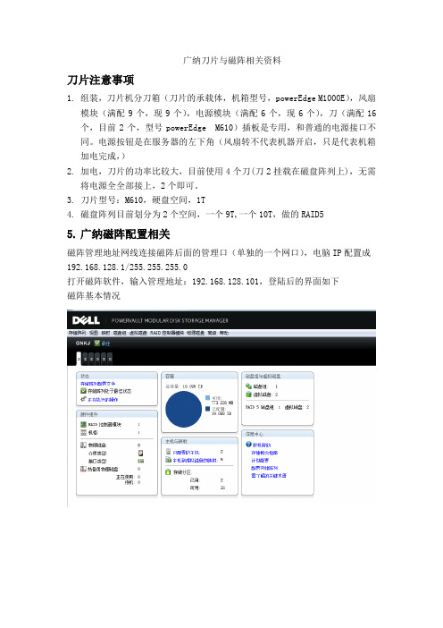
广纳刀片与磁阵相关资料刀片注意事项1.组装,刀片机分刀箱(刀片的承载体,机箱型号,powerEdge M1000E),风扇模块(满配9个,现9个),电源模块(满配6个,现6个),刀(满配16个,目前2个,型号powerEdge M610)插板是专用,和普通的电源接口不同。
电源按钮是在服务器的左下角(风扇转不代表机器开启,只是代表机箱加电完成,)2.加电,刀片的功率比较大,目前使用4个刀(刀2挂载在磁盘阵列上),无需将电源全全部接上,2个即可。
3.刀片型号:M610,硬盘空间,1T4.磁盘阵列目前划分为2个空间,一个9T,一个10T,做的RAID55.广纳磁阵配置相关磁阵管理地址网线连接磁阵后面的管理口(单独的一个网口),电脑IP配置成192.168.128.1/255.255.255.0打开磁阵软件,输入管理地址:192.168.128.101,登陆后的界面如下磁阵基本情况磁阵其他网卡的配置截图(连接服务器所用)网卡0网卡16.刀片服务器背板网卡注意事项刀片服务器所用的背板网卡属于一个交换机,每个刀片的网口实际都已经默认连接,2个背板网卡A1,A2。
也就是说A1,A2各插了一根网线,分别是接磁阵和192.168.4.0/24,以后新加服务器,如果网段不变的话,不需要再接新的网线(里面可以划分 VLAN,实际来说,A1板卡和A2办卡各是一个VLAN)查看交换机的配置笔记本网线连接服务器背板Cmc 的Gb口登陆CMC:192.168.0.120界面如下:可以从这里看到背板的交换机序列号。
7.服务器冷备步骤1)服务器安装好系统,装好相应的软件,将ISCSI发起连接调试好,在控制面板---iscsi发起---配置好服务端的IP地址(刀2用的192.168.130.101),然后点击登录即可2)备用服务器的IP地址不填,而且把网卡分别命名为联通和磁盘阵列,禁用备份服务器的网卡(以免造成IP地址冲突),3)主服务器出现故障时,启用网卡,配置好原服务器的地址.4)在磁盘阵列中,找到cc存储,右键---主机端口标示符更换,更换时自动回出现已登录的备用服务武器的串号(需核对计算机名称),点击更换即可磁阵安装一、硬件安装:1、磁阵柜安装到机柜,将硬盘安装至磁阵柜中,注意需按下硬盘前按钮,将硬盘打开,装入磁阵柜中厚将硬盘前合住即为安装硬盘成功。
poweredge-m1000e用户手册

Dell PowerEdge M1000e 机柜用户手册管制型号: BMX01注、小心和警告注: “注”表示可以帮助您更好地使用计算机的重要信息。
小心: “小心”表示可能会损坏硬件或导致数据丢失,并说明如何避免此类问题。
警告: “警告”表示可能会造成财产损失、人身伤害甚至死亡。
© 2013 Dell Inc. 保留所有权利。
本文中使用的商标: Dell™、Dell 徽标、Dell Boomi™、Dell Precision™、 OptiPlex™、Latitude™、PowerEdge™、PowerVault™、PowerConnect™、OpenManage™、EqualLogic™、Compellent™、KACE™、FlexAddress™、Force10™、Venue™和 Vostro™是 Dell Inc. 的商标。
Intel®、Pentium®、Xeon®、Core®和 Celeron®是 Intel Corporation 在美国和其他国家或地区的注册商标。
AMD®和 AMD Opteron™、AMD Phenom™以及 AMD Sempron™是 Advanced Micro Devices, Inc.的注册商标或商标。
Microsoft®、Windows®、Windows Server®、Internet Explorer®、MS-DOS®、Windows Vista®和 Active Directory®是 Microsoft Corporation 在美国和/或其他国家或地区的商标或注册商标。
Red Hat®和 Red Hat® Enterprise Linux®是 Red Hat、Inc. 在美国和/或其他国家或地区的注册商标。
M1000e配置文档

M1000e配置配置文档第一部分:供电部分PDU的规格如下图,连接如下。
机箱结构后视图。
经常DSP或者用户到电话进来,说按power 按钮无法开机,就是因为要等Enclosure加电之后,再按开机按钮才能生效。
具体的信息如下,Enclosure is on Standby Power,Enclousure Power is ON,然后去按开机按钮,机器就能顺利启动了。
具体的信息看下面的图片。
第二部分:CMC管理配置部分CMC具体命令行:(配置的时候可以参考)? <subcommand> -- display usage summary for a subcommandarp -- display the networking arp tablechassisaction -- execute chassis or switch power-up/down/cycle or KVM powercycleclrraclog -- clear the CMC logclrsel -- clear the System Event Log (SEL)cmcchangeover -- Changes the redundant state of the CMC from active to standby and vice versaconfig -- modify CMC configuration propertiesdeploy -- deploy blade by specifying required propertiesfeature -- display features active on the chassis/ feature deactivationfeaturecard -- Feature card status and list the available featuresfwupdate -- update the firmware on a CMC, server, IOM inf, or KVM getassettag -- display asset taggetchassisname -- get the chassisnamegetconfig -- display CMC configuration propertiesgetdcinfo -- display general I/O module and DC misconfiguration informati ongetflexaddr -- display the MAC addresses per slot/status of Flexaall slots and fabricsgetioinfo -- display general IO informationgetkvminfo -- display the KVM module informationgetled -- display the LED settings on a modulegetmacaddress -- get MAC/WWN addressesgetmodinfo -- get module configuration and status informationgetniccfg -- display network settings for modulesgetpbinfo -- get power budget status informationgetpminfo -- get power management status informationgetraclog -- display the CMC loggetractime -- display the current CMC timegetredundancymode -- gets the redundancy mode of the CMCgetsel -- display records from the System Event Log (SEL) getsensorinfo -- display system sensorsgetslotname -- gets the name of the slot in the chassisgetssninfo -- display session informationgetsvctag -- display service tag informationgetsysinfo -- display general CMC and system informationgettracelog -- display the CMC diagnostic trace logifconfig -- display network interface informationnetstat -- display routing table and network statisticsping -- send ICMP echo packets on the networkracdump -- display CMC diagnostic informationracreset -- perform a CMC reset operationracresetcfg -- restore the CMC configuration to factory defaults serveraction -- perform system power management operationssetassettag -- set the asset tag for the specified modulesetchassisname -- sets the name of the chassissetflexaddr -- enable/disable the Flexaddress feature on a per fabric, perslot basissetled -- set state of the LEDs on a modulesetniccfg -- modify network configuration propertiessetractime -- set the time on the CMCsetslotname -- sets the name of the slot in the chassissetsysinfo -- set the chassis name and chassis locationsslcertview -- display a CA/server certificate in the CMCsslcsrgen -- generate a certificate CSR from the CMCsslresetcfg -- generate a new self-signed certificatetestemail -- test CMC e-mail notificationstesttrap -- test CMC SNMP trap notificationsCMC 如何设置IP$ racadm setniccfg -s 192.168.128.120 255.255.255.0 192.168.128.1Static IP address modified successfully$ 等候15秒生效$ ifconfigeth0 Link encap:Ethernet HWaddr 00:1A:A0:FF:Finet addr:192.168.0.120 Bcast:192.168.0.255 Mask:255.255.255.0UP BROADCAST MULTICAST MTU:1500 Metric:1RX packets:0 errors:0 dropped:0 overruns:0 frame:0TX packets:0 errors:0 dropped:0 overruns:0 carrier:0collisions:0 txqueuelen:0RX bytes:0 (0.0 B) TX bytes:0 (0.0 B)$ ifconfigeth0 Link encap:Ethernet HWaddr 00:1A:A0:FF:F7:04UP BROADCAST MULTICAST MTU:1500 Metric:1RX packets:0 errors:0 dropped:0 overruns:0 frame:0TX packets:0 errors:0 dropped:0 overruns:0 carrier:0collisions:0 txqueuelen:0RX bytes:0 (0.0 B) TX bytes:0 (0.0 B)$ ifconfigeth0 Link encap:Ethernet HWaddr 00:1A:A0:FF:F7:04inet addr:192.168.128.120 Bcast:192.168.128.255 Mask:255.255.255.0UP BROADCAST MULTICAST MTU:1500 Metric:1RX packets:0 errors:0 dropped:0 overruns:0 frame:0TX packets:0 errors:0 dropped:0 overruns:0 carrier:0collisions:0 txqueuelen:0RX bytes:0 (0.0 B) TX bytes:0 (0.0 B)重置CMC命令racreset -- perform a CMC reset operationracresetcfg -- restore the CMC configuration to factory defaultsCMC获取Enclosure信息$ racadm getsysinfoCMC Information:CMC Date/Time = Fri, 31 Oct 2008 05:13:16 AMPrimary CMC V ersion = 1.20Standby CMC V ersion = N/ALast Firmware Update = Thu Sep 25 01:36:04 2008Hardware V ersion = X28Current IP Address = 192.168.0.120Current IP Gateway = 192.168.0.1Current IP Netmask = 255.255.255.0DHCP Enabled = 0MAC Address = 00:1A:A0:FF:F7:04Current DNS Server 1 = 0.0.0.0Current DNS Server 2 = 0.0.0.0DNS Servers from DHCP = 0Register DNS CMC Name = 0DNS CMC Name = cmc-6T9N72XCurrent DNS Domain =Chassis Information:System Model = PowerEdgeM1000eSystem AssetTag = 00000Service Tag = 6T9N72XChassis Name = Dell Rack SystemChassis Location = [UNDEFINED]Power Status = ONCMC获取模块信息$ racadm getmodinfo<module> <presence> <pwrState> <health> <svcTag> Chassis Present ON Not OK 6T9N72X Fan-1 Present ON OKFan-2 Present ON OKFan-3 Present ON OKFan-4 Present ON OKFan-5 Present ONFan-6 Present ON OKFan-7 Present ON OKFan-8 Present ON OKFan-9 Present ON OKPS-1 Present Online OKPS-2 Present Failed(No AC) Not OKPS-3 Present Online OKPS-4 Not Present N/A N/A N/APS-5 Not Present N/A N/A N/APS-6 Not Present N/A N/A N/ACMC-1 Present Primary Not OK N/A CMC-2 Not Present N/A N/A N/A Switch-1 Present ON OK 4ZXW7F1 Switch-2 Present ON OK 3P9HSB1 Switch-3 Not Present N/A N/A N/A Switch-4 Not Present N/A N/A N/A Switch-5 Not Present N/A N/A N/A Switch-6 Not Present N/A N/A N/A Server-1 Not Present N/A N/A N/AServer-2 Not Present N/A N/A N/AServer-3 Not Present N/A N/A N/AServer-4 Present OFF OK 188Q72X Server-5 Not Present N/A N/A N/AServer-7 Not Present N/A N/A N/A Server-8 Not Present N/A N/A N/A Server-9 Not Present N/A N/A N/A Server-10 Not Present N/A N/A N/A Server-11 Not Present N/A N/A N/A Server-12 Not Present N/A N/A N/A Server-13 Not Present N/A N/A N/A Server-14 Not Present N/A N/A N/A Server-15 Not Present N/A N/A N/A Server-16 Not Present N/A N/A N/A KVM Present ON OK通过CMC连接交换机connect switch-2connect: acquiring remote port.Connected to remote port.Escape character is '^\'.console>console>HELPHELP:Special keys:DEL, BS .... delete previous characterCtrl-A.... go to beginning of lineCtrl-E .... go to end of lineCtrl-F .... go forward one characterCtrl-B .... go backward one characterCtrl-D .... delete current characterCtrl-U, X .... delete to beginning of lineCtrl-K .... delete to end of lineCtrl-W .... delete previous wordCtrl-T .... transpose previous characterCtrl-P .... go to previous line in history bufferCtrl-R .... rewrites or pastes the lineCtrl-N .... go to next line in history bufferCtrl-Y.... print last deleted characterCtrl-Q .... enables serial flowCtrl-S .... disables serial flowCtrl-Z, end ... return to root command promptTab, <SPACE> .. command-line completionExit .... go to next lower command prompt? .... list choices--More-- or (q)uitconsole>?enable Enter into user privilege mode.help Display help for various special keys.logout Exit this session. Any unsaved changes are lost. password Change the password.ping Send ICMP echo packets to a specified IP address. quit Exit this session. Any unsaved changes are lost. show Display Switch Options and Settings.statistics Display detailed statistics for a specific port orfor the entire switch.console>console>?enable Enter into user privilege mode.help Display help for various special keys.logout Exit this session. Any unsaved changes are lost. password Change the password.ping Send ICMP echo packets to a specified IP address. quit Exit this session. Any unsaved changes are lost. show Display Switch Options and Settings.statistics Display detailed statistics for a specific port orfor the entire switch.console>enableconsole#show running-config!Current Configuration:!System Description "PowerConnect M6220, D.9.21.2, VxWorks5.5.1"!System Software V ersion D.9.21.2!configurestackmember 1 1exitip address 192.168.2.1 255.255.255.0exitconsole#当然如果您是第一开机设置可以使用前面的LCD屏幕设置(第一次设置完成后,二次设置就需要是使用命令行设置,或者到CMC web界面下设置)。
Dell M1000e刀片服务器

刀片服务器配置文集第1章DELL M1000eDELL M1000E背面图全配是9个风扇,6个电源,2个CMC模块(1主2从),1个iKVM模块,6个I/O模块(A1/A2只能用于以太网交换机模块,B1/B2,C1/C2可接以太网交换机,光纤通道交换机模块)。
其前面为刀片插槽,可装半高刀片/全高刀片或混装。
前面板左下角是鼠标/键盘/显示器接口,它在选配了iKVM模块之后起作用,通过连接鼠标/键盘/显示器接口之后,利用键盘上的PrintScreen按键可访问不同刀片上的控制台(即连接到不同的刀片服务器上,输入序号1,2,…16即可,17表示CMC控制台)。
当连接到前面板上的鼠标/键盘/显示器接口时,iKVM模块上的VGA输出会禁用。
§1.1 初始配置在系统硬件连接之后,即可进行初始配置。
最初要配置CMC系统。
需要注意的是在完成I/O模块配置之前不要打开刀片上的电源。
初始配置时仅需打开CMC 控制模块上的电源按扭以启动机箱。
初始可选用超级终端连接到CMC控制模块的Console口(115200, 8 data bits, no parity, 1 stop bit, no flow control)。
以root/calvin登陆CMC系统,# getniccfg 获取当前CMC网络接口信息。
# setniccfg –s 192.168.16.5 255.255.255.0 192.168.16.1 设置静态地址( IP, Netmask, Gateway)。
(缺省静态地址为192.168.0.120)# racadm racreset 激活新的网络设置。
之后即可通过IE浏览器进行配置和管理。
https://192.168.16.5§1.2 配置iDRACDell PowerEdge M1000e 机箱背板上集成了iKVM以及相关的远程管理工具。
Chassis Management Controller机箱管理控制器简称CMC,通过每个刀片服务器上集成的Dell 远程访向控制器(Remote Access Controller,iDRAC),完全可以对Dell PowerEdge M1000e中的每个刀片系统以及机箱进行远程监控和管理。
解读戴尔M1000E刀片服务器

解读戴尔M1000e刀片效劳器戴尔公司一直致力于刀片效劳器产品的研究与。
早在xx年,戴尔PowerEdge M1000e刀片效劳器就是惠普和IBM刀片系统强有力的竞争者。
较其他竞争对手相比,戴尔刀片效劳器的核心竞争力表达在能够以较低的本钱,快速进行部署与管理。
早在xx年,戴尔公司只有屈指可数的几款刀片效劳器。
只拥有双路和四路的刀片效劳器,并没有高密度的刀片效劳器,更没有专为虚拟化和存储特定的刀片效劳器。
如今,只需一个10U的M1000e刀片效劳器就可轻松应对。
从硬件的角度来看,戴尔PowerEdge M1000e表现十分出色,是一款高密度的刀片效劳器,并且使单个刀片的数据处理能力大大增加,如PowerEdge M420、用于存储的PS-M4110刀片效劳器,以及For 10的MXL 10G/40G的刀片交换机,相比以前,大大提高了刀片效劳器的灵活性和可扩展性。
与此同时,戴尔更加精益求精,还为M1000e的刀片效劳器提高了管理工具的使用效率以减轻工作负载。
For 10作为戴尔的刀片式交换机在管理时需要将工作集中管理到一起,那样将需要集中管理更多的机箱。
在此期间,戴尔提供了较为完善的刀片效劳器系统使集中管理变得简便。
全新的EqualLogic PS-M4110存储效劳器是戴尔首次亮相的刀片效劳器。
这是一个半高的刀片效劳器,可容纳14个2.5英寸的磁盘和两个冗余控制器。
通过两个内置的10G接口将每个控制器关联起来。
PS4100阵列与EqualLogic iSCCI SAN阵列具有相同的功能,都只需占用较小的空间来实现。
EqualLogic PS-M4110刀片式效劳器拥有14个热插拔硬盘和热插拔控制器。
在效劳器前端有一个LED显示屏,可显示每个磁盘和控制器的当前工作状态,并且每个磁盘和控制器的顶部指示灯也会显示。
EqualLogic PS-M4110刀片式存储效劳器代号为“巨人”,它可容纳14TB的数据存储量,配有14个1TB的SAS磁盘,也可划分成5个SSD 和9个SAS磁盘。
- 1、下载文档前请自行甄别文档内容的完整性,平台不提供额外的编辑、内容补充、找答案等附加服务。
- 2、"仅部分预览"的文档,不可在线预览部分如存在完整性等问题,可反馈申请退款(可完整预览的文档不适用该条件!)。
- 3、如文档侵犯您的权益,请联系客服反馈,我们会尽快为您处理(人工客服工作时间:9:00-18:30)。
目录:M1000E 刀片服务器基本概况M1000E 的初始安装iKVM 的基本操作CMC 的常用基本操作iDRAC 的常用基本操作1、M1000E 刀片服务器基本概况:组成:必读:M1000E 刀片服务器简单的理解就是将16个(半高)的服务器(内置了DRAC卡)、以太网络交换机、光纤存储交换机、InfiniBand交换机通过一个特制的机箱整合在一起的集合体。
9个风扇、6个电源模块、机箱背板(BP)为上述设备提供运行环境支撑和物理连接;2个CMC(CMC是机箱管理控制台的缩写,另一个CMC是可选的)和KVM为上述设备提供管理和监控。
M1000E的示意图:M1000E 背部2、M1000E的初始安装必读:M1000E的满配需要60A的220V供电,当使用一个60A的PDU时,一个PDU便可满足;使用30A PDU时,需要使用两个。
整机总共可提供6个供电模块PSU,PSU1-3 是一组;PSU4-6是第二组,两组互为冗余。
1)电源的连接:60A的PDU AC输入插头(白色为用户方提供,灰色部分为DELL提供)60A的PDU60A的PDU上的标签2)开机、首次开机初始化、关机。
接通电源后,按机箱左下角的开机按钮开机,机箱开始加电。
各个刀片的加电是单独控制的,和机箱的开机无关。
注意:机箱关机,会导致所有刀片关机。
3、iKVM的基本操作1)ME1000E的刀片是通过KVM来共享键盘鼠标显示器的,在机箱后部和前部各有一个接口,两组接口有相同的功能。
RJ-45接口是用来级联到的外部KVM的,不能用来连接网络。
2)KVM 的OSD菜单是靠键盘的“Print Screen”(打印屏幕)键呼出的。
CMC也是一台计算机,因此也有自己的显示屏幕。
用鼠标或键盘光标选中想要查看的刀片,按回车键,即可切换到相应刀片的屏幕。
3)KVM 菜单上各刀片的名字,可以在CMC上修改。
4、CMC的常用基本操作必读:在KVM上使用选择到CMC,便切换到CMC的显示界面,CMC自身的命令非常少,最常用只有3条:racadm,connect,ifconfig,其他的命令都是这些命令的子命令,也就是其他命令都是作为这几条命的参数执行的。
例如,要恢复CMC到出厂值,便要在CMC的“$”提示符下输入:racadm racresetcfg(回车) ,子命令racresetcfg便是作为racadm的参数执行的。
CMC 默认用户名:rootCMC 默认密码:calvin1)CMC IP地址初始化:机箱初次加电,可以在机箱前LCD面板为CMC设定IP地址,IP地址用于在远程用web或命令行对CMC进行访问。
IP地址一旦在LCD上设定好,便只能察看,不能修改。
2)CMC IP地址的察看:ifconfig \\用于察看CMC的IP地址,例如:$ ifconfigeth0 Link encap:Ethernet HWaddr 00:1A:A0:FF:F7:04inet addr:192.168.128.120 Bcast:192.168.128.255 Mask:255.255.255.0UP BROADCAST MULTICAST MTU:1500 Metric:1RX packets:0 errors:0 dropped:0 overruns:0 frame:0TX packets:0 errors:0 dropped:0 overruns:0 carrier:0collisions:0 txqueuelen:0RX bytes:0 (0.0 B) TX bytes:0 (0.0 B)$3)CMC IP地址的修改:racadm setniccfg \\用于察看CMC的IP地址,例如:$ racadm setniccfg -s 192.168.128.120 255.255.255.0 192.168.128.1 Static IP address modified successfully等候大约15秒才能生效$ ifconfigeth0 Link encap:Ethernet HWaddr 00:1A:A0:FF:F7:04UP BROADCAST MULTICAST MTU:1500 Metric:1RX packets:0 errors:0 dropped:0 overruns:0 frame:0TX packets:0 errors:0 dropped:0 overruns:0 carrier:0collisions:0 txqueuelen:0RX bytes:0 (0.0 B) TX bytes:0 (0.0 B)$ ifconfigeth0 Link encap:Ethernet HWaddr 00:1A:A0:FF:F7:04inet addr:192.168.128.120 Bcast:192.168.128.255 Mask:255.255.255.0 UP BROADCAST MULTICAST MTU:1500 Metric:1RX packets:0 errors:0 dropped:0 overruns:0 frame:0TX packets:0 errors:0 dropped:0 overruns:0 carrier:0collisions:0 txqueuelen:0RX bytes:0 (0.0 B) TX bytes:0 (0.0 B)$4)察看CMC 系统信息:racadm getsysinfo \\用于察看CMC系统信息,例如:$ racadm getsysinfoCMC Information:CMC Date/Time = Fri, 31 Oct 2008 05:13:16 AMPrimary CMC Version = 1.20Standby CMC Version = N/ALast Firmware Update = Thu Sep 25 01:36:04 2008 Hardware Version = X28Current IP Address = 192.168.0.120Current IP Gateway = 192.168.0.1Current IP Netmask = 255.255.255.0DHCP Enabled = 0MAC Address = 00:1A:A0:FF:F7:04Current DNS Server 1 = 0.0.0.0Current DNS Server 2 = 0.0.0.0DNS Servers from DHCP = 0Register DNS CMC Name = 0DNS CMC Name = cmc-6T9N72XCurrent DNS Domain =Chassis Information:System Model = PowerEdgeM1000eSystem AssetTag = 00000Service Tag = 6T9N72XChassis Name = Dell Rack SystemChassis Location = [UNDEFINED]Power Status = ON$5、察看CMC机箱内部的模块和模块名称racadm getmodinfo \\用于察看机箱内部的模块清单,例如:$ racadm getmodinfo<module> <presence> <pwrState> <health> <svcTag>Chassis Present ON Not OK 6T9N72XFan-1 Present ON OKFan-2 Present ON OKFan-3 Present ON OKFan-4 Present ON OKFan-5 Present ON OKFan-6 Present ON OKFan-7 Present ON OKFan-8 Present ON OKFan-9 Present ON OKPS-1 Present Online OKPS-2 Present Failed(No AC) Not OKPS-3 Present Online OKPS-4 Not Present N/A N/A N/APS-5 Not Present N/A N/A N/APS-6 Not Present N/A N/A N/ACMC-1 Present Primary Not OK N/ACMC-2 Not Present N/A N/A N/ASwitch-1 Present ON OK 4ZXW7F1Switch-2 Present ON OK 3P9HSB1Switch-3 Not Present N/A N/A N/ASwitch-4 Not Present N/A N/A N/ASwitch-5 Not Present N/A N/A N/ASwitch-6 Not Present N/A N/A N/AServer-1 Not Present N/A N/A N/AServer-2 Not Present N/A N/A N/AServer-3 Not Present N/A N/A N/AServer-4 Present OFF OK 188Q72XServer-5 Not Present N/A N/A N/AServer-6 Not Present N/A N/A N/AServer-7 Not Present N/A N/A N/AServer-8 Not Present N/A N/A N/AServer-9 Not Present N/A N/A N/AServer-10 Not Present N/A N/A N/AServer-11 Not Present N/A N/A N/AServer-12 Not Present N/A N/A N/A$6、连接到其他设备的配置界面connect 命令用于连接到其他模块的命令行界面,例如:要配置网络交换机1,便输入 $connect switch-1$ connect switch-1connect: acquiring remote port.Connected to remote port.Escape character is '^\'. (由交换机界面退回CMC界面输入 ctrl+\ )console>7、重启动CMC$ racadm racreset8、恢复CMC到出厂值(CMC反初始化)$ racadm racresetcfg9、CMC的Web访问将CMC的GB-1端口连接至管理网络,在任何可以ping到CMC IP地址的web浏览器中输入“https://CMC IP/即可访问到CMC web接口。