forge泄压阀说明书
63EG 型泄压阀或背压阀 说明书

63EG 型和 1098-63EGR 型D 100315X C N 2指导手册资料号 51102008 年 11月63EG 型泄压阀或背压阀简介手册内容本手册为带有 6358, 6358B, 6358EB 型或 6358EBH 型指挥器的 63EG 型泄压阀或背压阀、以及带有 6358B 型指挥器的 1098-63EGR 型泄压阀提供了的操作说明和零件清单。
对于选配的指挥器用过滤器 252 型或 P590 系列,以及与其配合使用的装置的操作说明和零件清单,可在另外单独的手册中找到。
产品说明63EG 型和 1096-63EGR 型指挥器作用式泄压阀可用于液体和气体的场合。
63EG 型也适用于限流背压或旁路应用工况。
这两种主阀都采用了可快速更换阀内件的构造,便于快速维护。
技术规格技术规格章节及表 1 到 3 列出了各种 63EG 型和 1098-63EGR 型的技术规格。
出厂时,调压器的技术规格印在主阀的铭牌上。
对于 1098-63EGR 型, 技术规格印在执行机构的上部阀膜箱体。
指挥器的控制弹簧作用范围印在指挥器弹簧箱体上,指挥器限流孔代码用一个字母表示,它印在指挥器阀体底部,靠近旁路出口: S 代表红色标准直径限流孔 (钻孔尺寸 57),L 代表蓝色大直径限流孔 (钻孔尺寸 47),用于液体的场合,或用 H 代表黄色小直径 (钻孔尺寸 70),用于高增益限流孔。
指挥器说明以下的指挥器配置可用于 63EG 型或 1098-63EGR 型泄压阀或背压阀。
泄压阀6358B, 6358EB 型指挥器或 6358EBH 型泄压指挥器可与泄压阀配合使用。
当泄压阀运行时,指挥器不断地排放压力。
当入口压力低于设定压力时,指挥器停止排图 1. 63EG 型泄压阀或背压阀W6955图 2. 1098-63EG 型泄压阀W3003-1*63EG 型和 1098-63EGR 型2技术规格可供配置带 6358 系列指挥器的 63EG 型带 6358B 型指挥器的 1098-63EG 型主阀阀体和端口连接方式(1, 2)主阀阀体尺寸, 英寸 (DN)端口连接方式和额定值铸铁钢或不锈钢1, 2 (25, 50)NPT , CL125B FF , 或 CL250B RF 法兰连接NPT , BWE, SWE, CL150 RF , CL300 RF , CL600 RF , 或 PN 16/24/40 法兰连接2, 3, 4, 6, 8 x 6(50, 80, 100, 150,200 x 150)CL125B FF , 或CL250B RF 法兰连接BWE, CL150 RF ,CL300 RF , CL600 RF , 或 PN 16/24/40 法兰连接最大泄压 (入口(3)) 压力(2)63EG 型: 400 psig (27,6 bar)1098-63EGR 型: 82 psig (5,6 bar)最大执行机构压力(2) (标准尺寸 40, 仅适用于 1098-63EGR 型)最大设定压力(4): 65 psig (4,5 bar) 最大工作压力(3): 75 psig (5,2 bar)最大紧急情况压力: 82 psig (5,6 bar)设定泄压/背压控制范围(4) 见表 2主阀端口直径和阀塞行程阀体尺寸,英寸 (DN)端口直径, 英寸 (毫米)阀塞行程, 英寸 (毫米)1 (25)2 (50) 1.312.38 (33) (60)0.751.13 (19) (29)3 (80)4 (100) 3.384.38 (86) (111) 1.502.00 (38) (51)6 和 8 x 6 (150 和 200 x 150)7.19 (183)2.00 (51)主阀流量特性线性 (标准) 或 Whisper ®Trim III (可选)主阀流量方向上部通过阀座垫圈流入和外部通过阀笼流出温度范围(2)腈橡胶 (NBR):-20° 至 180°F (-29° 至 82°C) 氟橡胶 (FKM):0° 至 300°F -18° 至 149°C)水温限制在 0° 至 180°F (-18° 至 82°C ) 三元乙丙橡胶 (EPDM):-20° 至 275°F (-29° 至 135°C)可选项• 铝或不锈钢制的 252 型指挥器用过滤器 • 黄铜制的 P594-1 型过滤器 • 压力计(5)大致重量 (包括指挥器) 63EG 型1 英寸 (DN 25): 35 磅 (16 公斤)2 英寸 (DN 50): 55 磅 (25 公斤)3 英寸 (DN 80): 95 磅 (43 公斤)4 英寸 (DN 100): 145 磅 (66 公斤) 6 英寸 (DN 150): 330 磅 (150 公斤)8 x 6 英寸 (DN 200 x 150): 670 磅 (304 公斤) 1098-63EGR 型1 英寸 (DN 25): 65 磅 (29 公斤)2 英寸 (DN 50): 85 磅 (39 公斤)3 英寸 (DN 80): 125 磅 (57 公斤)4 英寸 (DN 100): 175 磅 (79 公斤)6 英寸 (DN 150): 360 磅 (163 公斤)8 x 6 英寸 (DN 200 x 150): 700 磅 (318 公斤)1. 通常也提供 DIN (或其它) 额定值和端口连接: 请向费希尔公司销售服务部门或销售代理商咨询。
泄压阀作业指导书
泄压阀作业指导书
1、泄压阀结构:
首站使用的泄压阀是先导式泄压阀,它主要分为阀体部分、阀前和阀后部分。
阀前部分又包括球阀、压力表、平衡管和导阀。
2、泄压阀各部分功能:
压力表:显示阀前管线压力。
平衡管:将阀前压力引至阀腔内,用于阀芯平衡。
导阀:导阀上有调整螺丝,通过调整螺丝可以设置泄放压力。
3、泄压阀工作原理:
首站泄压阀的设计压力是10.6MP a,当阀前压力低于设计压力时,导阀关闭,泄压阀前后压力平衡;阀前压力高于设计压力时,导阀开启,通过平衡管先将一小部分油品泄放至阀后管道,所以阀腔压力降低,前端压力推动阀芯后移,使油品大量泄放。
安全泄压阀说明书
A X 742X-安 全 泄 压 阀使 用 说 明 书株洲南方阀门股份有限公司10 1625 40一、用途用于供水和输水系统,可对压力波快速反应和快速释放,防止压力急剧增高而损坏管线及设备,特别适用于高层楼房消防系统泄压,并可安装于减压阀下游,确保系统安全不超压。
二、特点1、准确且保持不变的安全稳定压力,一旦超压,泄压阀能充分打开及时泄压。
2、关闭速度可调,消除压力波动。
3、隔膜传动机构将操作滞后现场减小到最少。
4、它可安装在任何位置,不需改变压力设定值或从管路上折除就可进行维修和检查。
三、技术参数1、公称压力:1.0Mpa 1.6Mpa 2.5Mpa 4.0Mpa2、出口压力:PN1.0MPa调节范围0.3~0.9MpaPN1.6MPa调节范围0.5~1.4MpaPN2.5MPa调节范围0.5~2.4MpaPN4.0MPa调节范围1.0~3.5Mpa3、启闭动作压力:0.05MPa4、适用介质:原水、清水5、适用温度:0~80℃四、结构示意图安全泄压阀是由主阀和先导阀及其它外装附件组成,其主阀由阀体、膜片、阀杆、组件、主阀板、阀座等组成,通过外装附件及先导阀实现安全泄压。
图一结构示意图1、闸阀2、过滤器3、先导阀4、压力表五、工作原理安全泄压阀是通过进口压力的变化,反馈到导阀上,再由导阀来控制主阀板的启闭,使管路中的压力能保持安全稳定的状态,一旦超压,能及时泄压。
当管路中的压力超过先导阀的设定值时,进口压力水从控制管进入先导阀膜片下腔内,使其压力增高,推动先导阀阀杆上移,先导阀阀板打开,主阀控制室上腔的水从先导阀和控制管排泄,在进口压力水的作用下,主阀板打开。
当管路中的压力下降至低于设定值时,先导阀膜片下腔的压力降低,先导阀阀杆下移,使其阀板关闭。
从而导致从控制管进入先导阀再到主阀控制室上腔的压力水的压力增高,在上腔水压作用下主阀板关闭。
六、安装注意事项1、安装前,先检查阀各部件是否完好,紧固件、附管件联接是否牢固、可靠。
背压泄压阀说明书

目录第1节 简介概论特点工作原理型号编号外形尺寸技术参数第2节 安装开箱安全措施安装第3节 压力设定与调整准备工作背压阀的压力设定泄压阀的压力设定第4节 维护备件设备维修第5节故障查询第6节部件第1节简介一、 概论当设备出现故障或化学管路堵塞出现过压时,VS系列隔膜泄压阀可用来保护可调容积泵和其他设备,VB系列背压阀在泵运行时在排出管路中提供一个比吸入管路更高的压力。
这确保了在吸入行程时不会有流体由于惯性或虹吸作用流入排出管路。
这些阀在泵运行时还可作为防虹吸阀。
二、 特点1、高可靠性/低成本2、PTFE/EPDM复合膜片3、泄压阀0~1.0Mpa可调背压阀0~0.3Mpa可调4、可安全释放排泄至吸入管路或溶液箱中5、背压阀具有防虹吸功能6、防松调节螺钉7、机加工结构,坚固三、 工作原理VS系列隔膜式泄压阀在正常情况下,泄压阀不泄放,内部弹簧压紧支承块,使隔膜顶住阀座将排放口密封,当系统压力高于阀门设定压力时,化学品流出并回流至化学容器或计量泵吸入管路(在现场可通过调节螺钉在0~1.0Mpa范围内设置压力,泄放压力应设置高于系统压力约0.1Mpa。
建议在管线上安装压力表以便现场调整泄放压力)。
膜片保持顶启,直到系统压力再次下降到阀门设定压力以下,弹簧将隔膜压下封住排放口,继续正常的运行。
VB系列隔膜式背压阀通过抵消吸入惯性和防止工艺压力低于吸入压力时的系统虹吸,消除由投加点压力波动引起的投加量变化,在计量泵排出端保持一定的压力以确保精确计量。
(在现场可通过调节螺钉在0~0.3Mpa范围内设置背压)。
在计量泵的排出行程压力作用于隔膜,将其顶启,而使计量泵的液体通过。
当计量泵的排出流量减少至0时(吸入行程),弹簧使隔膜复位,将计量泵出口和阀门之间的低压液体分开,这样就保证了泵出口止回阀恒定的正压。
四、 型号编码五、 外形尺寸六、 技术参数1、工作压力:1.0Mpa2、工作温度:PVC、PVDF阀体 max60℃316SS阀体 max90℃3、压力设置范围:VS 0~1.0MpaVB 0~0.3Mpa出厂设定:VS 0.5MpaVB 0.2Mpa(200L/h流量状态)4、工作性能曲线(参见背压阀,泄压阀流量压力曲线图)第2节安装一、开箱当承运人接受货物时,货物就从工厂发出,转交到用户,一切在运输过程中发生的损坏用户都应立即通知承运人并要求索赔,在正式接收前,仔细检查运输包装,确认在运输过程中没有发生损坏,打开包装,确认所有附件都完好,数量正确,并与装箱单核对无误。
泄压阀的正确使用方法
泄压阀的正确使用方法
泄压阀是一种广泛应用于工业领域的安全装置,其作用是通过释放过高的压力来保护设备和系统的安全运行。
正确使用泄压阀对于保证设备的正常运行和工作环境的安全非常重要。
下面是一些泄压阀的正确使用方法:
1. 选择合适的泄压阀:泄压阀的选择应根据系统的压力范围、介质以及流量来确定。
确保所选泄压阀的额定工作压力和流量能够满足系统的需要。
2. 安装位置:泄压阀的安装位置应在系统中的高压区域,以便能够及时检测到并释放过高的压力。
同时,还需注意避免安装在易受外部物体影响的位置,以免影响泄压阀的正常工作。
3. 安全阀管道:泄压阀安装时应连接安全阀管道,以便将释放的压力导向安全区域。
管道的材质和尺寸应符合相关标准,并定期检查管道的状况,确保畅通无阻。
4. 定期检查和维护:泄压阀应定期进行检查和维护,确保其正常运行。
检查包括清洁泄压阀表面、检查密封件和弹簧是否正常,以及测试泄压阀的开启和关闭压力是否符合标准。
如发现任何故障或异常情况,应及时进行修理或更换。
5. 注意排放压力:在实际操作中,需要根据系统的要求和安全规定,设置泄压阀的开启压力和关闭压力。
开启压力应设定在系统所能承受的最大压力之下,而关闭压力则应设定在系统正常工作范围内。
6. 培训操作人员:对于使用泄压阀的操作人员,应提供相关的培训和指导,使其了解泄压阀的工作原理、正确使用方法以及应急处理措施,以确保其能够正确操作和维护泄压阀。
总之,正确使用泄压阀对于保护设备和系统的安全运行至关重要。
遵循以上方法,可以确保泄压阀能够有效地工作,提供全面的安全保障。
氮气式水击泄压阀安装和维护手册2013版(中英对照)
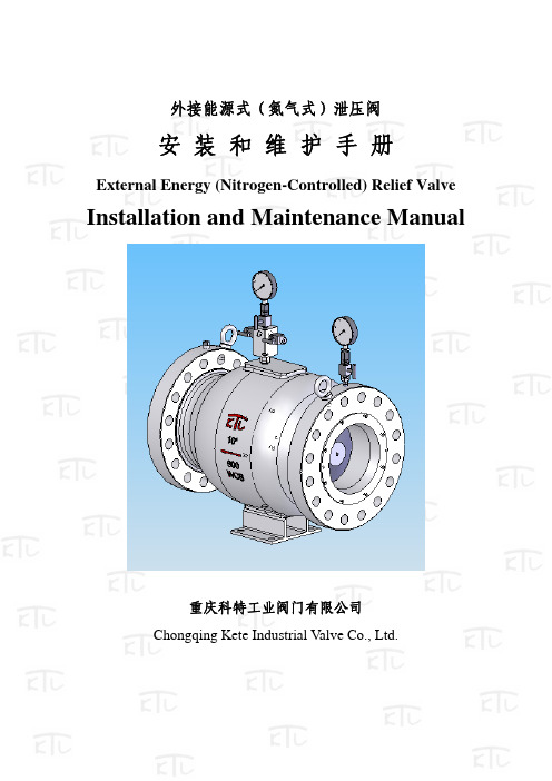
外接能源式(氮气式)泄压阀安 装 和 维 护 手 册External Energy (Nitrogen-Controlled) Relief ValveInstallation and Maintenance Manual重庆科特工业阀门有限公司Chongqing Kete Industrial Valve Co., Ltd.一、产品结构及工作原理I. Structure and Working Principles1、产品结构:如图11. Structure, as shown in Fig. 1阀座valve seat滑塞腔 Plug chamber滑塞 PlugFig. 12、工作原理:2. Working Principles:外接能源式(氮气式)泄压阀的工作主要依赖于对泄压阀滑塞内腔的压力控制,其滑塞内腔控制动力由外供氮气瓶通过氮气控制柜减压系统对其控制压力进行调控。
The External Energy (Nitrogen-Controlled) Relief Valve works mainly depending on the pressure control to its inner plug chamber. The control force to the inner plug chamber is supplied from external nitrogen bottle, with its pressure regulated by a reducing system in the nitrogen distribution cabinet.当输送管线正常工作时,滑塞在内腔设定压力作用下将滑塞紧紧的与主阀座贴合,使泄压阀处于正常关闭状态;当管线发生水击,异常升压,超过其滑塞内腔所设定的安全控制压力时,在压差的作用下滑塞打开,通过滑塞外腔开始泄压并报警,管线压力下降,当管线压力恢复正常工作压力时,滑塞与阀座紧紧贴合,恢复关闭状态,停止泄放。
压力释放阀说明书[中英]
![压力释放阀说明书[中英]](https://img.taocdn.com/s3/m/2e96aecc76c66137ef06192d.png)
压力释放阀PRESSURE RELEASE VALVE使用说明书OPERATION INSTRUCTION明远电器设备SHENYANG MINGYUAN ELECTRIC EQUIPMENT CO., Ltd.本说明书适用于我公司生产的系列变压器用压力释放阀,阐述其用途、性能、规格、技术参数、使用及安装,供用户参考。
The Operation Instruction is applicable to pressure release valve of a series of transformers manufactured by our company, indicating its application, performances, specifications, technical parameters, usage and installation for uses’ reference.1. 压力释放阀用途和性能压力释放阀适用于油浸式电力变压器、电力电容器及有载分接开关等,用来保护油箱。
当油浸式变压器在运行中出现故障时,由于线圈过热,使一部分变压器油汽化,变压器油箱中压力迅速增加,这时压力释放阀在2ms迅速动作,释放压力,保护油箱不致变形或爆裂。
油箱的压力再升高而达到开启压力时,压力释放阀应再次动作,直到油箱的压力降到正常值。
由于压力释放阀动作后能可靠关闭,油箱外的水和空气不能进入油箱,变压器部不会受大气污染。
1.Application and performancePressure release valves play a vital role in the protection of oil-immersed electrical equipments, such as transformers, high voltage switch gears, capacitor and on load tap-changers, etc. This device can prevent the oil-immersed electrical equipment from deformation or rupture. Should a fault occur in such electrical equipment, from deformation of rupture? Should a fault occurring in such electrical equipment, they are instantaneously vaporize the oil causing extremely rapid build-up of gaseous pressure? If mounting this type pressure release device on the oil-tank, when the pressure reaches to its opening pressure, it opens automatically within 2ms and relieves the pressure.2.型号、规格及基本参数Type, specification and technical parameters2.1 型号的含义 Meaning of typeY S F□—□ / □□□特殊环境代号(Special environment)带机械信号标“J”(“J”:mechanical signal)带信号开关标“K”(“K”:electrical signal)两者都带标“KJ”(“KJ”:Both with signal)喷油有效口径(Caliber of oil-gushing tube)mm开启压力(Opening pressure)kPa设计序号(Design serial number)阀(valve)释放(release)压力(pressure)注:特殊环境代号 note: special environment:TA: 干热带地区 dry tropicTH: 湿热带地区 humid tropicT: 干、湿热带地区 dry、humid tropic例:YSF16-55/130KKJT开启压力为55kPa,喷油口径为φ130mm,带电信号、机械信号。
高压泄压阀SA.SL.HPRV001.H.4864说明书
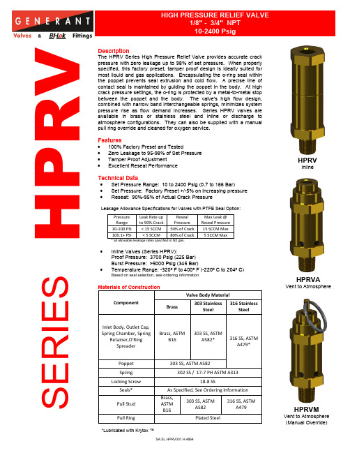
1/8" - 3/4" NPT 10-2400 PsigH P R VDescriptionThe HPRV Series High Pressure Relief Valve provides accurate crack pressure with zero leakage up to 98% of set pressure. When properly specified, this factory preset, tamper proof design is ideally suited formost liquid and gas applications. Encapsulating the o-ring seal withinthe poppet prevents seal extrusion and cold flow. A precise line of contact seal is maintained by guiding the poppet in the body. At high crack pressure settings, the o-ring is protected by a metal-to-metal stopbetween the poppet and the body. The valve’s high flow design,combined with narrow band interchangeable springs, minimizes system pressure rise as flow demand increases. Series HPRV valves are available in brass or stainless steel and inline or discharge toatmosphere configurations. They can also be supplied with a manualpull ring override and cleaned for oxygen service.Features• 100% Factory Preset and Tested• Zero Leakage to 95-98% of Set Pressure • Tamper Proof Adjustment• Excellent Reseat PerformanceTechnical Data• Set Pressure Range: 10 to 2400 Psig (0.7 to 166 Bar)• Set Pressure: Factory Preset +/-5% on increasing pressure •Reseat: 90%-95% of Actual Crack PressureLeakage Allowance Specifications for Valves with PTFE Seal Option:Pressure Range Leak Rate up to 90% Crack Reseal Pressure Max Leak @ Reseal Pressure 10-100 PSI < 15 SCCM 50% of Crack 15 SCCM Max 100.1+ PSI< 5 SCCM80% of Crack5 SCCM Max* all allowable leakage rates specified in N2 gas.• Inline Valves (Series HPRV): Proof Pressure: 3700 Psig (225 Bar) Burst Pressure: >5000 Psig (345 Bar)•Temperature Range: -320º F to 400º F (-220º C to 204º C)Based on seal selection, see ordering informationMaterials of ConstructionComponentValve Body MaterialBrass303 StainlessSteel316 StainlessSteelInlet Body, Outlet Cap, Spring Chamber, SpringRetainer,O'Ring SpreaderBrass, ASTMB16 303 SS, ASTMA582*316 SS, ASTM A479*Poppet 303 SS, ASTM A582Spring 302 SS / 17-7 PH ASTM A313Locking Screw18-8 SSSeals* As Specified, See Ordering Information Pull Stud Brass,ASTMB16303 SS, ASTM A582 316 SS, ASTMA479Pull RingPlated SteelS E R I E S*Lubricated with Krytox ™HPRVInlineHPRVAVent to AtmosphereHPRVMVent to Atmosphere (Manual Override)Dimensional Data Flow DataInlet (NPT)HPRV HPRM HPRVAHex A B C D E F1/8”3.344.24 3.30 4.20 2.87 3.77 1”1/4"3/8”1/2" 4.16 5.06 4.27 5.18 3.56 4.46 1-1/4” 3/4" 5.90 7.14 5.44 6.70 4.82 6.13 1-3/4” Dimensional data is stated in inches.SetPressureRangeHPRV HPRVA and HPRVM10-1250 1251-2400 10-1250 1251-2400 Inlet (NPT) Orifice Kd Orifice Kd Orifice Kd OrificeKd1/8” .215 0.14.215 0.16.215 0.57.215 0.651/4".275 0.27 .275 0.653/8”1/2" .515 0.20 .275 0.27 .515 0.35 .2750.653/4"See “HPRV-750 Flow Datasheet” (Not offered below 70 PSI)Kd is stated at 110% of Nominal Set Pressure.Orifice sizes are stated in inches.Consult factory for proper sizing or flow requirements, flow curves available on request. Ordering InformationPROPER COMPONENT SELECTION – When specifying a component, the total system design must be considered to ensure safe and trouble-free performance.Intended component function, materials compatibility, pressure ratings, installation, environment and maintenance are the responsibility of the system designer.1865 Route 23 South PO Box 768 Butler, New Jersey 07405 973.838.6500 Fax 973.838.4888。
- 1、下载文档前请自行甄别文档内容的完整性,平台不提供额外的编辑、内容补充、找答案等附加服务。
- 2、"仅部分预览"的文档,不可在线预览部分如存在完整性等问题,可反馈申请退款(可完整预览的文档不适用该条件!)。
- 3、如文档侵犯您的权益,请联系客服反馈,我们会尽快为您处理(人工客服工作时间:9:00-18:30)。
Forge Motorsport 2.0T FSI Replacement Bypass Valve KitPlease thoroughly read through and familiarize yourself with these instructions prior to beginning the installation process of any component. Please also ensure that the vehicle and engine have cooled down sufficiently to avoid risking skin burns or other injury.Tools Required:- Vehicle jack and jack stands or access to a vehicle lift- 5mm Allen wrench or Allen socket with extension- 3mm Allen wrench- 1/8 Inch Allen Wrench- Razor blade or Xacto knife to cut vacuum line- Blue colored medium strength semi-permanent Loc-Tite thread lockerBegin by safely lifting the vehicle and then locating the turbo and the OEM electronically controlled bypass valve/solenoid, which will be bolted to the compressor cover of the turbo.- On the MK5 VW GTI and Jetta GLI, the B6 Passat, and the 8P Audi A3, the OEM valve will be bolted to the turbo located on the lower passenger side of the rear of the motor.- On the Golf ED30 and R, Leon Cupra, Scirocco R and Audi S3 the valve is located at the top of the engine bay at the front directly behind the radiator- On the B7 Audi A4, the OEM valve will be bolted to the turbo located on the passenger side of the motor towards the front underside of the carOnce located, disconnect the electrical connector/plug for the valve and you can now use your5mm Allen wrench or socket to remove the three 5mm Allen bolts which secure the valve to the turbo. You must be sure to save the OEM valve bolts as they will be reused later.With the OEM valve removed from the turbo, you can now temporarily install the Forge replacement valve reusing the OEM bolts with them only hand-tightened. This initial installation is only temporary so as to find an appropriate mounting location for the solenoid and to find the appropriate lengths for the vacuum lines you will use on your car.First, attach the solenoid to your choice of the supplied brackets using the two supplied 5mm Allen bolts. The solenoid can be mounted anywhere in the engine bay within reach of the solenoid wiring.For the purpose of generating these instructions, we will mount the solenoid bracket using one of the bolt holes for the new Forge valve as shown below. You do not have to install the solenoid bracket in this manner on your application if you would prefer a different location.With the new Forge valve loosely mounted to the turbo, and a location selected for the solenoid and it loosely mounted as well, measure to find appropriate lengths for the vacuum hose connections between the valve and the solenoid.Please use the plumbing diagram below for the appropriate locations to connect the vacuum lines. As stipulated in the plumbing diagram, the plumbing MUST be as shown or the valve may fail to operate properly or possibly at all.Once you have determined the length of vacuum line you will need between each connection of the valve and the res pective connection on the solenoid, you can cut the appropriate lengths of line from the included s pool. The lengths you cut and use will be based on where in the engine bay you have chosen to mount the solenoid.You can now remove everything from the car to secure the lines between the valve and solenoid as shown above.With the valve and solenoid plumbed together and the lines secured with the included zip ties, you can now permanently mount the valve and solenoid bracket.Use your 5mm Allen wrench to bolt the new Forge valve to the turbo from where the OEM valve was removed, again, reusing the OEM valve bolts.Securely clip the supplied wiring harness to the solenoid (it is a tight fit) before you mount the solenoid in the engine bayWith the valve securely mounted to the turbo and the solenoid bracket also secured at your desired location within the engine bay, you can reconnect the OEM wiring harness plug to the connection on the end of the Forge wiring harness.We will now move on to the vacuum tap piece which will need to be connected to the intake manifold. The vacuum tap has 3 tap provisions and is supplied with multiple vacuum nipples and blanking plugs for you to select the number of provisions you will need on your application.- One nipple must be used at a minimum for valve operation. (largest port nipple only)- A second nipple can be used for a boost gauge tap. (s mallest port nipple only)- A third provision is available and can be used for whatever it may be needed for on your application.- All unused port provisions must be plugged with the supplied port plugs. (3mm Allen)It is highly recommended that all vacuum nipples and port plugs are secured with blue colored, medium strength, semi-permanent Loc-Tite thread locker. If not used, the vacuum nipples and port plugs may back out, becoming lost and/or causing a vacuum/boost leak.To install the vacuum tap, you will need to unclip the PCV hose connection on the intake manifold. This can be found up and to the right of the throttle body while looking at the manifold. Pinch down on the two ribbed sections releasing the clips and pull the hose out of the manifold barb.Next, you will slide the manifold tap over the barb until the edge of the lip can no longer be seen through the grooves in the tap. Once the lip is no longer visible, insert the black plastic C-clip to secure the tap in place. The o-ring seals are very tight and secure, so this may take a small bit of effort.Once the manifold tap is held securely in place with the plastic C-clip, reattach the PCV hose to the barb at the end of the tap.If you are using some sort of PCV “fix” or “bypass”, h owever, you will need to reconnect whatever components are supplied with that product. The barb on the end of our manifold tap is the same size and shape as the OEM manifold barb, so any hoses or caps that connect to the manifold barb will connect to the barb on our tap as well.From the appropriate nipple on the manifold tap (largest port), run a length of vacuum tubing along the top of the motor, around the passenger side, following the fuel rail and fuel lines, down to the remaining linear port on the solenoid you mounted previously. (See plumbing diagram) Secure both ends of this line using two of the included zip ties. If any s pare zip ties are available, use them to secure this vacuum line to the fuel rail and/or fuel lines.Your valve installation is now complete, and you can now enjoy all of the benefits that a more reliable and performance orientated bypass valve has to offer. You should notice slightly quicker spool, less tapering, more responsive mid-range, and overall better valve and boost response.打造赛车 2.0T FSI 置换旁路阀工具包请彻底阅读并熟悉这些指令之前,在开始任何组件的安装过程。