博世CMS7000报警系统用户手册
BOSCH报警系统详细介绍及如何使用
MAP II 利用这些关系所产生的动态 “特性” 来决定这个 信号是否应激发一个报警
被动红外的工作原理
监察性能 – 防遮挡
确保探测器能够看到探测区域 探测那些对探测器的蓄意破坏 使用短距离主动红外反射探测器
应用在:
DS720i
PIR 的原理
监察性能- 一步处理
一步处理 (FSP) 不会牺牲对其他物体的误报, 而允许真实的对人类目标的立即反应. 根据振幅、极性、范围和持续时间,调整它的 灵敏度,FSP 消除安装者要根据应用情况来选 择灵敏度水平的需要. 每个探头都是独立处理,当全部都认为是报警 时才会启动报警继电器.
DS720i 长距离三技术探测器
距离最远的三技术探测器 信号处理:动态分析II(MAPII) 监察性能:微波及被动红外监察+防遮挡+动 态监测 特殊防遮挡功能: 微波防遮挡:可侦测微波被反射材料遮挡 (如木材、金属等) 红外防遮挡:可侦测探测器被布等物体或
探测范围:标准27米× 21米 标准长距:91米×5米 可选长距:37米×8米
t e r s A B C D E F G H I
25 0
Feet
7.5 50
I
Side V iew
0 Meters
F e e t
15 3 0
10 5 0 0 Feet
O-Q J-N A-I
50 Mirror adjus ted to -3
M e t e r s
一:透镜 将变化的红外能量聚焦到探测元件上 可以是反射镜片或菲涅耳透镜 由镜片或透镜上的小刻面来决定 探测区域或角度
室外三技术外探测器 OD850
CMS7000用户手册

CMS7000用户手册一 CMS7000安保系统简介-------------------2二 CMS7000安全系统的基本概念及术语-------7三连接报警主机-------------------------16四 CMS7000安装--------------------------18五 CMS7000启动与操作员登录--------------20六 CMS7000参数设置----------------------23七 CMS7000报警主机管理------------------34八 CMS7000用户与防区管理----------------37九 CMS7000报警监控与处理----------------45十 CMS7000巡更管理----------------------55十一 CMS7000数据库安全与备份管理----------63附录: CMS7000快速操作指南------------------------------67___________________CMS7000 User Manual__________________ P/N 48426B Page 11. CMS7000安全防范系统概要1.1 CMS7000安全防范系统组成CMS7000安全防范系统一般由报警传感器,报警主机,通讯模块,输入/输出控制设备以及运行于PC上的CMS7000组成。
目前CMS7000支持DS7400报警主机和DS可视对讲系统。
1.2 CMS7000安全防范系统工作原理CMS7000安全防范系统通过设置在受保护区间的传感器装置接收,诸如:烟雾,红外,开关等报警信号,传送到报警主机;报警主机根据预先设定的报警主机参数判断火警,盗警,紧急状态等报警类型并作出相应报警和控制动作,同时将报警事件通过串行通讯接口传送到运行CMS7000的PC,CMS7000根据用户对逻辑防区的定义对报警主机的报警事件作出相应处理。
博士报警主机说明
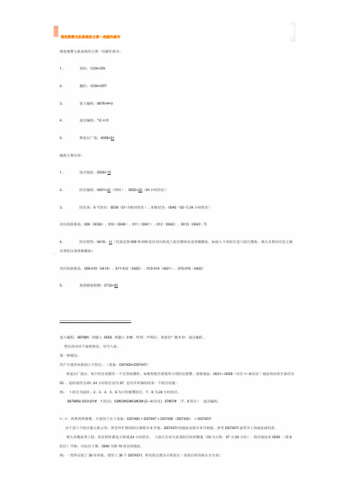
博世报警主机系统的主要一些操作指令博世报警主机系统的主要一些操作指令:1、设防:1234+ON2、撤防:1234+OFF3、进入编程:9876+#+04、退出编程:*按4秒5、恢复出厂值:4058+01编程主要内容:1、综合地址:0000+152、防区编程:0001+21(即时)、0002+22(24小时防区)3、防区表:9号防区:0039(01-为即时防区)、010防区:0040(02-为24小时防区)对应的表格是:009(0039)、010(0040)、011(0041)、012(0042)、0013(0043)等4、防区特性:0419:11(代表是第009和010防区对应的是八防区模块还是单路模块,如添入1则对应是八防区模块,填人0则对应是主板自带防区或单路模块)对应的表格是:009-010(0419)、011-012(0420)、013-014(0421)、015-016(0422)5、取消接地检测:2732+00-------------------------------------------------------------进入编程:9876#0 再输入4058, 再输入01#,听到一声响后,再按住* 键4秒,退出编程。
然后再对应下面的情况,对号入座。
第一种情况:用户只使用本机的八个防区。
(设备:DS7400+DS7447)恢复出厂值后,每个防区的都有一个自身的属性,如果你想全部使用立即防区报警,请将地址:0031—0038(对应1—8防区)地址的内容全部改为03 ,延时就改为01, 24小时防区改为07, 也可以单独的改某一个防区的值。
例:1防区为延时,2、3、4、5、6为立即报警防区,7、8为24小时防区。
9876#0à 0031(01# 1防区) 03#03#03#03#03# (2—6防区) 07#07# (7、8防区)退出编程。
<二> : 简单周界报警,只使用了以下设备:DS7400 + DS7447 + DS7436(DS7430)+ DS7457I由于前八个防区被主机占用,所有外扩展的防区都将从9开始。
bosch周界报警系统(CMS-7000)

德国Bosch博世周界报警系统目录第一节客户需求 (3)第二节防盗报警系统设计依据 (3)第三节:系统概述 (4)3.1设备布置 (5)3.2设备连接 (5)3.3系统供电 (5)第四节:系统功能 (6)4.1报警功能: (6)4.2主要设备性能指标 (6)第一节客户需求周界安全防范报警系统要求做到:1.周界全面设防,无盲区和死角;2.探测设备抗不良天气环境干扰能力强;3.防区划分适于报警时准确定位;4.报警中心具备语音/警笛/警灯提示;5.翻越区域现场报警,可实现同时发出警笛/警灯、警告;6.报警中心可控制前端设备状态的恢复;7.进行报警中心报警状态、报警时间记录;8.可对事件记录进行打印。
第二节防盗报警系统设计依据我公司设计的周界报警系统设计完全符合所有中华人民共和国之条例和规范,包括:1、民用建筑电气设计规范 JGJ/T16-922、中国电气装置安装工程施工及验收规范 GBJ232-823、建筑与建筑群综合布线系统工程设计规范 CECS 72.954、系统接地分型式及安全技术要求 GB14050-935、 IEEE 电气及电子工程师学会-民用建筑闭路技术电视系统工程技术规范6、安全防范工程程序与要求 GA/T75-947、安全防范工程费用概预算编制办法 GA/T70-94第三节:系统概述报警子系统主要由主动红外对射探测器、对射安装支架、报警控制主机、控制键盘、地址编码器、警号、报警电子地图管理软件、电脑以及管线组成。
各报警点可以任意分区,控制其集体或单独布撤防,在电脑上对各报警进行实时监控,该子系统采用先进、成熟的传感技术和信号分析技术,对企图翻越围墙的行为实施打击控制,以确保小区住户的安全。
3.1设备布置目前根据实地情况,在周界安装室外红外对射探测器,共计计16组。
当布防时如果有人侵入则发生报警,实时的将本防范区域的报警信号、警情类型显示到报警主机键盘上,并触发报警信号,使操作人员能及时、准确地掌握警情,及时调动保安人员进行处理。
博世Bosch Security Engine (SEE) 用户手册说明书

uProvides command and control of devices from clients and serversuSupports the administration of intrusion and entry systems in G-Series Control Panels uSupports the Conettix D6100/D6600Communications Receiver/Gateway u Uses serial or Ethernet communication uProvides time schedule controlThe Security Engine (SEE), as one of the mainfunctional modules within the Building Integration System (BIS), is designed to control multiple G-Series Control Panels and to monitor alarms and events from these devices, as well as from security systems connected to the Bosch Conettix D6100/D6600Communications Receiver/Gateway.By combining all the common BIS features with its own, SEE lets you tailor an alarm and security management system to your own individual requirements.An unlimited number of control panel connections can be added in groups of two. Each BIS connection server supports a maximum of 32 control panel connections.System overviewThe Security Engine Module connects to G-SeriesControl Panels and updates and downloads personnel database information such as user data and skeds (time schedules) to control panels through channels.Installers can use the DX4010i Serial Interface Module to connect each control panel with a RS-232 serial cable to an open COM port on the PC. Installers can use the DX4020 Network Interface Module to connect each control panel through an Ethernet network.Each control panel stores relevant data and uses field events to make intelligent decisions. The SecurityEngine supports Remote Programming Software (RPS)configuration for G-Series Control Panels.The Security Engine connects to a Conettix D6100 or D6600 Communications Receiver/Gateway through a serial or Ethernet connection.Users can configure and monitor up to 500 accounts.The system is expandable up to 3,200 accounts for each Conettix Communications Receiver/Gateway.PC withSecurity Engine SoftwareD X4010iD X4020NetworkRS232SerialRS232SerialSDI BusSDI BusCommand Cen t erConett i x Rece i ver/Ga t ew ayG Ser i es PanelCar d ReaderG Ser i es PanelCar d ReaderCommand Cen t erG Series Control PanelsThe Security Engine supports the following control panels:•D9412GV2 and GV3•D9412G •D7412GV2 and GV3•D7412G •D7212GV2 and GV3•D7212G •D91121•D721211The D9112 and D7212 do not support access controlreaders.NoticeVersion 6.60 or higherThe G-Series Control Panels offer the following features and functions:•Built-in digital communicator with phone line.•Multiple telephone numbers, primary and duplicate paths with main and alternate destinations.•Programmable reports within each of four route groups.•Optional DX4020 network interface module for two-way communication over Ethernet networks.•Automatic test and status reports.Admin9000With Admin9000 the SEE offers additionaladministrative tools integrated into the BIS user interface. This central part of the Security Engine allows administrators to:•Manage a database of human resource information for up to 996 authorized users for each control panel •Change user authorization •Add or delete users•Manage skeds and define scheduled events •Design and print Photo ID badges •Print database reportsAlarm and Event ManagementSupported by the BIS user interface and the common BIS features you have a sophisticated alarm and event management showing the following information during an alarm:•Alarm description (event state)•Alarm date •Alarm time •Alarm location•Panel/detector address (if supported by device)•Operator working on alarm event •Other configurable itemsAlarm information from devices experiencing real-time events (such as door access) and alarm information from internal system events are logged in anintegrated MSDE database that supports Microsoft ®SQL Server ™ software.ReportsSecurity reports from the event log are stored in an HTML table that users can view using InternetExplorer. Other reports are in Crystal Reports ® format that users can view using the Crystal Reports Viewer included in Admin 9000.SEE optional accessoriesThe features listed below can be added optionally to the Security Engine installation.OPC9000 2 panel upgradeExtends the number of controllable G-series panels connected to a BIS Security Engine in steps of two.OPC6600 500 panel upgradeExtends the number of controllable accounts at aConettix D6100/6600 in steps of 500. The maximum is 3,200 accounts.Video-Badging for SEE/Photo ID badge printing optionActivates a component for designing and printing badges and the assignment to cardholders within the Security Engine.Video Verification option for SEEVideo verification extends the security level of your G-series access control system by using additional video equipment. When a reader is in video verificationmode the cardholder is not admitted directly. Instead the reader performs a request for entrance which appears as a message on the operator's screen.An action plan shows the operator the cardholder’s image as stored in the SEE user database inconjunction with a live image from a camera near the entrance/reader that sent the request. The operator compares both images and decides whether or not to open the door manually.Parts includedOrdering InformationSecurity Engine can be ordered in one of two ways:•as an integral part of an initial BIS configuration, inwhich case it is ordered along with a BIS basiclicense.•as an enhancement to an existing BIS configurationSEE 4.1 Basic PackageBasic license for the BIS module specifiedOrder number BIS-FSEE-BPA41SEE 4.1 additional 2 Panels (G Series)License for the addition to BIS of the feature specifiedOrder number BIS-XSEE-2PNL41SEE 4.1 additional 500 Accounts (D6x00)License for the addition to BIS of the feature specifiedOrder number BIS-XSEE-500P41Represented by:Americas:Europe, Middle East, Africa:Asia-Pacific:China:America Latina:Bosch Security Systems, Inc. 130 Perinton Parkway Fairport, New York, 14450, USA Phone: +1 800 289 0096 Fax: +1 585 223 9180***********************.com Bosch Security Systems B.V.P.O. Box 800025617 BA Eindhoven, The NetherlandsPhone: + 31 40 2577 284Fax: +31 40 2577 330******************************Robert Bosch (SEA) Pte Ltd, SecuritySystems11 Bishan Street 21Singapore 573943Phone: +65 6571 2808Fax: +65 6571 2699*****************************Bosch (Shanghai) Security Systems Ltd.203 Building, No. 333 Fuquan RoadNorth IBPChangning District, Shanghai200335 ChinaPhone +86 21 22181111Fax: +86 21 22182398Robert Bosch Ltda Security Systems DivisionVia Anhanguera, Km 98CEP 13065-900Campinas, Sao Paulo, BrazilPhone: +55 19 2103 2860Fax: +55 19 2103 2862*****************************© Bosch Security Systems 2015 | Data subject to change without notice 8776554123 | en, V7, 29. Jun 2015。
博世报警说明书

博世报警说明书
ቤተ መጻሕፍቲ ባይዱ报警主机操作说明
1、布防:1234+布防键信号灯Armed灯亮红色,主机:“嘟”“嘟”两声
2、撤防:1234+撤防键信号灯Armed灯灭,主机:“嘟”“嘟”两声
3、故障区旁路:1234+旁路键+防区号***,主机“嘟..”一声,表示该防区已经旁路,液晶屏上该防区即刻消除,此时可以布防其它防区(例如:旁路12防区按键:1234+旁路键+012,即可)。
注:如某一防区有故障,例如12防区,液晶屏上显示NO ready 12,此时主机不能对其它防区进行布防,需要将该防区旁路掉,方法参考上边第3点。
主机显示 READY TO ARM时,主机所有防区正常,可以布防。
博世安保系统防盗报警控制器用户指南说明书
键盘布防
有两种不同方法可将系统布防在外出模式下。
在外出模式下布防(方法 1) 输入您的用户码,然后按 [#] 键(例如 [2][5][8][0][0][#])。发出两声短鸣,外出 指示亮起。退出延 时开始计数。
强制布防
在有防区处于触发状态时布防系统,称为强制布防。如果系统无法布防,且发出一声长鸣,则表明不允 许强制布防。这时,您需要确保所有防区处于正常状态,或手动旁路相关防区,然后才能布防系统。 在防区设为强制布防允许的情况下,在退出延时结束时该防区被触发,则该防区会被确认为防区故障, 在键盘上对应的指示将恒亮。一旦该防区正常后,该防区将仍然有效。
3.3
4
4.1
1 - 按键 1:在外出模式下布防 2 - 按键 2:撤防 3 - 按键 1 和 2:同时按住两个按键可触发紧急报警。
钥匙开关布防
用户可通过钥匙开关对系统进行布防。当安装员设定好钥匙开关防区后,用户操作钥匙开关防区时,警 号会发出一声短鸣,确认系统进入布防。
在居家模式下布防
居家模式用于对现场周界和未使用区域进行布防,以探测可能进入现场的入侵者,并且允许您在自动隔 离的区域内自由活动。
用户指南
博世安保系统有限公司
防盗报警控制器
2
键盘操作快捷指南
ICP-KP8-CHI 八防区 LED键盘
键盘操作快捷指南 | zh-CHS 5
ICP-KP8L-CHI 八防区 LCD键盘
系统布/撤防 外出布防 居家布防 撤防 其他设置命令 添加/更改用户码 删除用户码 编程个人报警电话 取消个人电话报警 报警复位 隔离防区 忽略故障 查看系统故障 胁持报警 紧急报警 火警 医疗救护报警
Bodyguard 7000电子监测系统说明书
1 Safety-related information–Before using this product, carefully read these instructions for use and those of the associated products.–Strictly follow the instructions for use. The user must fully understand and strictly observe the instructions. Use the product only for the purposes specified in the intended use section (see section 3.4).–Do not dispose of the instructions for use. Ensure that they are retained and appropriately used by the product user.–Only trained and competent users are permitted to use this product.–Comply with all local and national rules and regulations associated with this product.–Only specialist, trained personnel are permitted to check, repair and maintain the product as described in these instructions for use and the technical manual. Further maintenance work that is not detailed in these instructions for use or in the technical manual must only be carried out by Dräger or personnel qualified by Dräger. Drägerrecommend a Dräger service contract for all maintenance activities.–Only use genuine Dräger spare parts and accessories when performing maintenance work, or the proper functioning of the product may be impaired.–Do not use a faulty or incomplete product. Do not modify the product.–Notify Dräger in the event of any component fault or failure.2 Conventions in this document2.1 Meaning of the warning notesThe following warning notes are used in this document to notify users of possible dangers. The meanings of the warning notes are defined as follows:2.2 Typographical conventions2.3 Registered trademarksThe trademarks listed are only registered in certain countries and not necessarily in the country in which this material is sold.2.4 Abbreviations3 Description3.1 Product overviewThe Dräger Bodyguard ® 7000 (Fig. 1) is an electronic monitoring system with an integral DSU. The system provides visual and audible information about the status of the breathing apparatus. Visible signals are provided by LEDs in the LED panel and on the LCD screen of the user interface (Fig. 2). Audible signals are emitted from an electronic sounder in the user interface. The audible signals are easily recognized with varying sound patterns to distinguish between different alarm types.The product is configured as a button version (Bodyguard ® 7000) or a tally version (Bodyguard ® 7000T). The main difference between the version types is the functionality of the distress signal unit. The button version can be used with the motion sensor of the automatic distress alarm deactivated. The tally version can only be used with the motion sensor activated.® 7000Fig. 2User interface 3.2 Feature description3.2.1 Power packThe power pack connects to the pressure module to supply power to the electronic monitoring system. The power pack types available forBodyguard ® 7000 have 5 replaceable 1.5 V batteries or a single 6.5 V rechargeable battery.Further details about the power pack and how each type is used is in the maintenance information (see section 6.5).3.2.2 User interfaceThe user interface has an LCD screen which shows the cylinder pressure, the time until the whistle activates, and other operational information. The screen has a backlight which illuminates when a user interface button is pressed, when an alarm activates, and when a status message appears on screen. The LED panel has one green, two blue, and two red LEDs which illuminate or flash to provide operational information.The left-hand and right-hand press buttons are used to control operating features of the electronic system. The button functions are described where applicable in these instructions for use.An internal sounder emits audible signals to notify the user aboutbreathing apparatus alarms and status messages. The sound patterns include continuous alarms and single or multiple tones. The sounder uses the tally slots as amplification chambers to provide clear and loud alarms.3.2.3 Cylinder pressure monitoringThe pressure module is connected to the breathing apparatus pneumatic system through the high-pressure hose. The electronic monitoringsystem displays cylinder pressure and TTW, and provides alarm signals at preset pressure levels.Time to whistleThe TTW is the calculated time in minutes until the EOST alarmactivates. The system uses the breathing apparatus air cylinder pressureand the current consumption rate of the wearer to calculate and display TTW. An initial calculation is made using a default consumption rate of 40 L/min. The calculation is then updated once per second based on the actual consumption rate of the wearer (a minimum consumption rate of 40 L/min is applied to the calculation).At the preset pressure, the EOST alarm commences (see section 4.2.3). The mechanical whistle on the breathing apparatus also commences at approximately the same time.Retreat alertRetreat alert is an alternative warning protocol that is available if it is applicable in the country of use (see section 4.5.5).3.2.4 Distress signal unitThe DSU provides automatic and manual distress alarms. The automatic distress alarm uses an internal motion sensor and timer to measure the time that the wearer has been motionless, in order to indicate that the wearer may be unconscious or trapped. The motion sensor activates a pre-alarm and a full alarm at predetermined intervals when the wearer does not move in excess of normal breathing movement. The manual distress alarm is activated by pressing the manual alarm button to call for help or attention. The alarm activation times are in section 9, and the alarm patterns are in section 4.2.3.A limitation of the automatic distress alarm is that the motion sensor detects movement or vibration to which the wearer is subjected. If the wearer is motionless but on a moving platform (on moving or vibrating machinery for example) the automatic distress alarm might not activate.3.3 Optional features and equipment3.3.1 Dräger PC LinkDräger PC Link is an RF communication device and software application which can read and configure Dräger electronic monitoring systems. Configurable settings and parameters include alarm patterns, warning levels, timings, and the start-up options (see section 4.4.3). Readable information includes the product identification details, the firmware versions, and a datalog (see section 3.3.2).PC Link can also read and write information on user ID cards which are available from Dräger for use with Bodyguard ® 7000 (see section 4.5.2). See the PC Link instructions for use or contact Dräger for more information.®3.3.2 DatalogThe datalog is a record of the event history which is automatically recorded in the system memory. The datalog stores approximately20 hours of the most recent system events (based on typical operational use of the system and the default datalog recording interval of20 seconds). The datalog can be downloaded and viewed using Dräger PC Link.3.3.3 Telemetry (Dräger PSS ® Merlin ®)Dräger PSS ® Merlin ® is a telemetry system which can be used withDräger electronic monitoring systems. When fitted, the telemetry system is used to monitor and control breathing apparatus wearers that aredeployed at an incident. The telemetry system uses radio communication to transmit status and information signals between deployed breathing apparatus wearers and an external entry control board or softwaresystem. See the PSS ® Merlin ® instructions for use or contact Dräger for more information.3.3.4 Head-up displayThe Dräger FPS ® 7000 HUD is a wireless head-up display which can be used with Dräger electronic monitoring systems. The HUD is a battery powered device that fits inside the mask, and has LEDs which display breathing apparatus cylinder pressure and battery status information. See the FPS ® 7000 HUD instructions for use or contact Dräger for more information.3.4 Intended useBodyguard ® 7000 is intended for use as an electronic monitoring system on compatible Dräger breathing apparatus. The monitoring systemprovides accurate cylinder pressure and remaining time information, and activates alarm signals at critical pressures. The integrated DSU provides clear, distinct, and easily recognized alarm signals that indicate wearer immobilization or a call for help or attention.3.5 Use in potentially explosive atmospheresBodyguard ® 7000 is type tested as suitable for use in potentiallyexplosive atmospheres. Electronic sub-assemblies are ATEX certified. All combinations are suitable for use in hazardous areas up to and including zone 0 and zone 20.3.6 Approval informationThe European standards, guidelines, and directives according to which this product is approved are specified in the declaration of conformity (see the declaration of conformity or /product-certificates).In addition, the product conforms with the following regulations.–DSU approval: BS 10999:2010 (specification for distress signal unitsfor the fire and rescue service). The product only conforms with this standard when configured as a tally version.–RF compliance: EN 61000-4-3 CE; and 30 V/m to ISO 11452 Part 2.Alert iconSignal word Consequences in case of non-obervance WARNINGIndicates a potentially hazardous situation. If not avoided, it could result in death or serious may also be used to alert against unsafe prac-tices.NOTICEIndicates a potentially hazardous situation. If not avoided, it could result in damage to the product or environment.►A triangle is used in safety statements to indicate possible ways ofavoiding the hazard.An information symbol is used for notes and additional useful information.1.Numbered paragraphs indicate that the information is sequential.–Dashed paragraphs indicate that the information is non-sequen-tial.Trademark Trademark ownerBodyguard ®DrägerDuracell ®Duracell U.S. Operations, Inc.FPS ®Dräger Merlin ®Dräger PSS ®DrägerAbbreviation ExplanationDSU Distress signal unit EOST End of service time HUD Head-up display ID IdentityLCD Liquid crystal display LED Light-emitting diode RF Radio frequency TTR Time to retreat TTWTime to whistle1User interface 2Connecting cable3Backup battery holder (not used on Bodyguard ® 7000)4Pressure module 5Power pack6High-pressure hose7Cylinder pressure 8Right-hand button 9TTW in minutes 10Tally11LED panel12Manual alarm button 13LCD screen14Left-hand button 15Radial segments123451110987D U。
博世迪信CMS7000
用 户 手 册
Detection systems Inc.
Copyright 2001~2002
CMS7000
Page 1
目录
CMS7000 快速操作指南-------------------------------------------2
CMS7000 用户手册 一 CMS7000 安保系统简介-------------------------------------------8 二 CMS7000 安全系统的基本概念及术语------------------------10 三 连接报警主机------------------------------------------------------14 四 CMS7000 安装------------------------------------------------------15 五 CMS7000 启动与操作员登录------------------------------------16 六 CMS7000 参数设置------------------------------------------------18 七 CMS7000 报警主机管理------------------------------------------27 八 CMS7000 用户与防区管理---------------------------------------29 九 CMS7000 报警监控与处理---------------------------------------33 十 CMS7000 巡更管理------------------------------------------------39 十一 CMS7000 数据库安全与备份管理--------------------43 十二 DS3MX 支持--------------------------------------45
博士报警主机说明
博世报警主机系统的主要一些操作指令博世报警主机系统的主要一些操作指令:1、设防:1234+ON2、撤防:1234+OFF3、进入编程:9876+#+04、退出编程:*按4秒5、恢复出厂值:4058+01编程主要内容:1、综合地址:0000+152、防区编程:0001+21(即时)、0002+22(24小时防区)3、防区表:9号防区:0039(01-为即时防区)、010防区:0040(02-为24小时防区)对应的表格是:009(0039)、010(0040)、011(0041)、012(0042)、0013(0043)等4、防区特性:0419:11(代表是第009和010防区对应的是八防区模块还是单路模块,如添入1则对应是八防区模块,填人0则对应是主板自带防区或单路模块)对应的表格是:009-010(0419)、011-012(0420)、013-014(0421)、015-016(0422)5、取消接地检测:2732+00-------------------------------------------------------------进入编程:9876#0 再输入4058, 再输入01#,听到一声响后,再按住* 键4秒,退出编程。
然后再对应下面的情况,对号入座。
第一种情况:用户只使用本机的八个防区。
(设备:DS7400+DS7447)恢复出厂值后,每个防区的都有一个自身的属性,如果你想全部使用立即防区报警,请将地址:0031—0038(对应1—8防区)地址的内容全部改为03 ,延时就改为01, 24小时防区改为07, 也可以单独的改某一个防区的值。
例:1防区为延时,2、3、4、5、6为立即报警防区,7、8为24小时防区。
9876#0à 0031(01# 1防区) 03#03#03#03#03# (2—6防区) 07#07# (7、8防区)退出编程。
<二> : 简单周界报警,只使用了以下设备:DS7400 + DS7447 + DS7436(DS7430)+ DS7457I由于前八个防区被主机占用,所有外扩展的防区都将从9开始。
- 1、下载文档前请自行甄别文档内容的完整性,平台不提供额外的编辑、内容补充、找答案等附加服务。
- 2、"仅部分预览"的文档,不可在线预览部分如存在完整性等问题,可反馈申请退款(可完整预览的文档不适用该条件!)。
- 3、如文档侵犯您的权益,请联系客服反馈,我们会尽快为您处理(人工客服工作时间:9:00-18:30)。
目录一、操作员登录 (3)二、基本操作 (3)1、使用步骤: (3)a、增加报警主机并设置参数 (3)b、查看报警主机通讯 (4)c、增加用户组并设置参数 (4)d、增加用户及防区 (4)e、用户/防区地图定位 (5)f、状态监控 (5)g、撤/布防 (5)h、报警处理 (6)三、C M S7000启动与操作员登录 (6)1、软件启动 (6)2、操作员登录 (6)3、CMS7000用户界面 (7)4、CMS7000基本操作 (8)四、参数设置 (9)1、C M S7000操作员权限管理 (9)2、权限说明: (9)3、CMS7000防区类型定义 (10)4、CMS7000系统参数设置 (12)五、报警主机管理 (13)1、报警主机参数设置 (13)2、主机参数说明 (14)六、用户及防区管理 (16)1、用户组管理 (16)2、用户管理 (16)3、用户属性设置 (17)4、防区管理 (17)七、报警监控管理 (19)1、报警监控 (19)2、报警处理 (20)3、报警历史记录管理 (21)一、操作员登录操作员名称:系统管理员口令:(无初始口令)●系统正式工作时务必将口令设置正确。
●可以在操作员权限管理中修改所以口令,也可以在登录管理中修改当前操作员的口令●如果需要关闭每次操作的口令检查,可以在菜单“参数设置”中“系统参数设置”下选择“登录后不再检查口令”项有效并保存。
●软件运行时不允许插拔软件加密锁,软件锁的安装与卸除必须关闭计算机电源。
二、基本操作所有功能可在系统菜单中选择,也可使用窗口下方的工具栏。
单击鼠标右键可弹出操作菜单,双击某些表格将显示详细资料。
参数设置时可单击参数设置向导工具栏按钮。
1、使用步骤:a、增加报警主机并设置参数激活报警主机窗口,增加报警主机并输入报警主机名称,选择串行口编号及设置连接参数(与报警主机实际设置对应),输入报警主机最大防区范围,输入报警主机最大分区范围,输入其它参数,确定保存。
与D S7400X I报警主机连接时必须设置采用硬件流控制。
b、查看报警主机通讯如果主机设置正确,激活通讯监控窗口,单击开始监控按钮,如果连接正确可在监控窗口收到数据。
c、增加用户组并设置参数激活用户组管理窗口增加用户组,输入用户组名称,确定保存。
d、增加用户及防区激活用户及防区管理功能,增加用户,选择用户所属的用户组,输入用户名称及其它参数,确定保存。
增加防区,选择防区所属用户,输入防区名称,选择防区类型,选择防区对应的报警主机,选择防区对应报警主机中的防区编号。
*增加防区之前确定报警主机防区设置情况,软件对应的默认状态为短路,开路触发报警,火警无延时。
如果设置完成后触发报警软件无相应报警事件,可以通过通讯监控窗口观察报警触发的消息是否与防区设置中的触发条件一致,或注意防区是否布防。
监控板中观察防区应为绿色。
●有报警尚未处理完时不能修改防区参数.●撤布防防区对其所属用户进行撤布防操作。
●巡更防区必须先在此设置才能在巡更管理中使用。
e、用户/防区地图定位激活用户防区定位窗口,如果用户及防区没有指定地图名称,则不能进行定位操作,图标前为红色,需要在上一步骤中设置,如果指定了地图但没有定位,出现黄色图标,选择联动地图有效,在左侧树中选择用户或防区时,左侧会显示相应的地图及已经定位在此地图上所有的防区。
打开定位锁后直接将没有定位的防区从左侧树中拖到右侧地图上即可。
重新定位只需直接在地图上拖动图标.如果重新定位到另一张地图,需要在用户/防区中设置新地图名称,再进行地图定位。
f、状态监控可以通过用户防区表,地图或状态表监控整个布防区域状态。
打开地图定位窗口后可以单击鼠标右健选择地图监控还是监控板监控,关闭定位树窗口可以全屏监控。
g、撤/布防激活撤/布防窗口,在树中选择要操作的用户组/用户/防区,然后根据需要进行各种操作,(报警主机必须处于布防状态相应布防才有效)。
当D S7400X I,D S3M X,D S6M X,B O S CH_V D P报警主机通过键盘进行撤布防操作时,将引起在C M S7000定义的相应防区进行自动的撤布防。
另外如果定义了撤布防开关类型的防区,则当这些防区被触发时,其所属用户的防区将相应进行自动的撤布防操作。
除此之外如果在周历表中定义了自动的撤布防计划,将在相应的时间对C M S7000的防区进行自动撤布防。
主机的撤布防操作将自动引起软件中具有相应分区值的防区撤布防,但通过软件对防区撤布防对报警主机没有任何影响。
h、报警处理报警发生时,如果设置正确将产生报警事件,当前报警事件表中出现报警消息,不同类型报警的显示颜色在报警类型和系统事件类型中设置。
双击报警事件列表将显示报警详细资料,在报警处理结果中输入报警处理结果或选择使用预置处理方案,单击确定按钮处理报警,报警将从当前报警显示表中删除,根据防区或系统事件中的设置将报警保存到历史记录数据库。
默认情况下每次处理报警必须确认权限,如果需要解除报警处理过程中每次确认权限操作,单击报警处理窗口中的解除权限检查按钮,有报警处理权限的管理员可以取消权限检查。
报警处理分为预处理与处理,预处理方案可以在防区定义时预先设置缺省值,处理结果可以在“系统参数设置”的系统设置中预先设置很多处理方案,实际处理时从中选择,也可以临时输入处理结果。
三、C M S7000启动与操作员登录1、软件启动单击C M S7000图标启动程序,如果程序已经运行,不能运行多个副本。
程序启动过程中会进行必要的初始化过程,初始化完成后出现登录界面。
2、操作员登录为了保证系统安全,C M S7000的使用人员必须登录后才能拥有相应的操作权限,初始安装的系统中拥有系统管理员用户,具有所有权限,其他用户的增加及权限设置有系统管理员管理。
系统管理员初始口令为空注意:第一次进入后应更改此口令。
3、CMS7000用户界面C M S7000运行时为全屏方式,用户界面主要包括主显示界面,弹出式窗口,系统菜单,工具栏。
主显示界面主要显示报警板,用户/防区地图,用户防区资料,巡更管理,报警历史记录等数据,但这些内容不能同时显示。
弹出式窗口主要显示报警处理界面,主机参数设置,系统参数设置等内容,允许同时弹出多个窗口,这些窗口覆盖主显示界面。
C M S7000所有功能全部在系统菜单中有相应选项,常用功能在工具栏中列出。
4、CMS7000基本操作C M S7000所有功能可以通过系统菜单实现,系统菜单如下:常用功能可以通过工具栏按钮实现,工具栏如下:四、参数设置1、C M S7000操作员权限管理C M S7000可以给予不同操作员以不同的操作权限,并且记录所有操作发生的时间与操作员以增强系统的安全性。
操作员权限管理界面2、权限说明:操作权限描述前有标记意味着操作员拥有此项操作权限,C M S7000的操作权限是通过限制操作界面的显示而实现的,没有相应操作权限的用户无法打开相应的操作界面。
修改口令时必须单击口令修改框中的确定按钮,否则口令无效,新口令与确认新口令必须完全相同以避免用户输入错误。
系统管理员不允许删除,也不允许修改权限,只允许修改口令。
3、CMS7000防区类型定义C M S7000软件使用防区来管理报警,巡更,撤布防等事件,不同的防区类型决定了防区发生报警时的不同处理方法,防区的种类是固定的,但其属性可以由用户设置,防区类型的属性决定了防区的缺省值,但每个具体的防区属性也可以改变,因此同一类型的防区可以具有不同的属性,防区类型缺省值只是提供了一个一般缺省参数。
系统已经定义的防区类型不允许删除,某些重要参数也不允许修改,用户自己可以新增防区类型并且决定其所有属性。
修改防区类型参数不能影响已经设置完成的防区,因此如果要相应防区的属性也根据新修改的防区类型属性变化,必须重新定义防区。
防区类型设置界面防区类型又称警区类型,它的参数决定了将来某一防区定义成此种防区类型时的初始缺省值。
防区类型参数说明防区类型名称:防区类型的名称,用来区别不同类型的防区,C M S7000目前定义有多种类型的防区,其中巡更防区,撤布防开关,B O S CH_V D P巡逻,布防开关,撤防开关是特别处理的防区,他们只能进行特殊操作。
巡更防区的报警事件将被作为巡更检查信号;撤布防开关的报警事件将作为对其它防区的撤布防命令处理。
触发条件:当报警主机接收到传感器的信号之后,会根据报警主机的参数设置来决定是否应该产生报警事件,一个报警的发生包含多个报警事件,如火警过程包括短路,火警,防区恢复,报警复位四个报警事件,而如果报警主机判断是误触发火警传感器时,只会报告短路,恢复两个报警事件。
C M S7000接收到这些报警事件之后,并不会对所有事件进行处理,而是根据触发条件来决定是否处理,如火警类型的防区如果触发条件是火警,只有当D S7400X I报警主机报告发生火警报警事件时才会触发火警类型的防区,而误触发产生的短路报警事件也会被C M S7000所忽略。
但如果火警类型的防区如果触发条件是短路报警类型,那么只要是短路报警事件都会被C M S7000软件作为火警处理,在这种情况下即使D S7400X I报警主机相应的防区设置为24小时防区,它的短路报警事件在C M S7000软件上也会被作为火警处理。
系统已经定义的防区不允许修改触发条件,与D S7400X I报警主机相关的前五种防区在短路或开路时都将动作。
4、CMS7000系统参数设置系统参数设置主要用来设置一些与C M S7000软件自身工作状态有关的参数。
必须首先单击修改按钮才可以开始修改系统参数。
自动操作设置当操作员有相当长的时间没有做任何操作时,有可能是离开了控制台,出于安全考虑,系统在规定时间内如果没有收到任何输入将自动退出登录,退出后需要重新登录才能进行操作,操作员应养成良好习惯每次离开控制台时主动进行退出登录操作。
使用地图监控设防区域时,C M S7000允许定义某一地图为主监控地图,在规定时间内监控窗口将自动切换到主监控地图进行监控。
报警处理结果设置C M S7000允许用户预先定义常用的报警处理结果的文字描述,在实际报警发生时可以从预先定义的处理结果选项中选择相应处理结果,也可以临时输入处理结果。
五、报警主机管理1、报警主机参数设置.主机参数设置主要用来设置P C与D S7400X I报警主机的通讯参数,为了便于对报警主机管理,还可设置报警主机名称,主机管理员及联系方式等参数。
2、主机参数说明主机编号:每台与P C相连的报警主机都具有唯一的一个编号,此编号不允许重复,自动产生,不需要用户输入。
主机名:为了便于管理,每台与P C相连的报警主机都具有唯一的名称,便于用户记忆和管理。
最小防区号:报警主机允许的最小防区编号,与最大防区号一起决定了D S7400X I报警主机允许连接的防区个数,应该根据具体的报警主机情况进行设置。