摄像头安装说明书
网络摄像头安装与使用手册

网络摄像头安装与使用手册为了帮助用户正确安装和使用网络摄像头,本手册将提供详细的步骤和相关注意事项。
在开始之前,请确保已经购买了合适的网络摄像头,并准备好使用的设备。
一、安装网络摄像头1. 硬件连接1. 将网络摄像头插入计算机的USB接口,并确保连接牢固。
2. 如果使用网络摄像头需要连接到路由器,请根据摄像头说明书提供的指引连接至路由器。
确保连接正确,以便正常进行网络通信。
2. 驱动安装1. 将随附的驱动光盘插入计算机,或者从官方网站下载最新版的驱动程序。
2. 根据驱动安装向导的指引,逐步完成驱动程序的安装。
在安装过程中,如果系统提示需要重新启动计算机,请按照提示进行操作。
3. 设置网络摄像头1. 打开计算机上的网络摄像头设置软件。
2. 按照软件提供的指引,进行网络摄像头的基本设置,比如设置分辨率、帧率等。
根据需要,还可以进行其他高级设置。
二、使用网络摄像头1. 软件启动1. 打开计算机上的网络摄像头相关软件。
2. 确保摄像头已经成功启动并连接到计算机。
2. 视频监控1. 在监控软件中选择摄像头设备,并点击“播放”按钮。
2. 观察监控画面,在需要时可以进行适当的调整,比如调整镜头方向、放大缩小画面等。
3. 录像功能1. 进入录像设置界面,在设置中选择录像保存位置和录像格式。
2. 点击录制按钮开始录像,在需要时再次点击停止录像。
4. 远程访问1. 如果网络摄像头支持远程访问,可以打开手机客户端或者通过浏览器访问摄像头的IP地址。
2. 根据产品说明书提供的指引,进行远程访问的相关设置。
注意事项:1. 在安装过程中,请遵循产品说明书提供的安装步骤。
如果遇到问题,应先检查硬件连接是否正确。
2. 请勿将摄像头暴露在日光直射的环境下,以免影响图像质量。
3. 定期检查摄像头镜头是否清洁,保持图像清晰。
4. 在远程访问中,为了确保网络摄像头的安全性,建议设置强密码并定期更改。
总结:本手册提供了网络摄像头的安装和使用指南,包括硬件连接、驱动安装、设置摄像头以及使用相关功能等方面的内容。
konka监控安装说明书

konka监控安装说明书首先:安装支架,用螺丝固定支架,网络摄像机与模拟摄像机的不同的地方是,网络摄像机是电源接口加网口,模拟摄像机是电源接口加视频接口,模拟摄像机和网络摄像机的电源接口是一样的通过网线,接到摄像机网口上,用12V2A的电源适配器接到电源接口,电源的另一端接到220V的电源上,网线的另一端接到交换机上,交换机的电源也要接好后端NVR接法,第一步,安装硬盘,机器本身不带硬盘得,打开NVR后盖,硬盘有两个接口与NVR相连,一个是电源接口,一个是视频接口,接好两个端口,固定好硬盘,NVR安装完毕。
再需要一根网线,一端接交换机,一端接NVR,网络录像机的接口有:电源接口,音频输入,输出接口,VGA是用来接显示器的,HDMI 是高清接口,USB是用来接鼠标或移动硬盘的,一般是给U盘进行备份的,给NVR接上电源,显示器接在VGA上,插上鼠标进行操作。
现在机器基本都在启动了,首先进入后,有个开机向导,可以根据向导进行操作下,设备启动是否开启向导,下一步,管理员密码海康默认的是12345,点确认,大家也可以修改管理员密码,下一步,下面设置一个IP地址,正常的不用自动获取的,我们用手动添加的,点下一步,录像机的硬盘如果没有初始化的话,硬盘会报警,提示你硬盘不能用,这是正常的,下面进行硬盘初始化,等它初始化到100%,如果硬盘属性是可读写,就是说硬盘是可用的,下一步,向导里面会出现我们刚添加的那台摄像机的IP地址,海康摄像机的默认IP地址是192.168.0.164.可以更改密码,IP地址,改好IP地址后,可以点添加,IP通道一,点录像,一个是定时录像,一个是移动侦测录像,定时录像的话就是说你设定一个时间,每时每刻都录像,移动侦测录像是物体移动时才录像,可以减少硬盘容量,为了保险起见,定时录像比较多,选择要录像的通道,点击确定,主菜单有单画面,多画面等,我们点4画面,登陆进去,录像机有几个功能,第一个有回放的功能,对录像进行回放,通道可以自己进行选择,鼠标右键退出,备份的话就是大家想到电脑上看,可以拷贝出来,在NVR的USB接口接上一个U盘就OK了,然后点一下搜索录像文件,然后点一下,进行快速备份,第三个手动操作,可以关闭和开启手动录像,第四个是硬盘管理,我们看一下硬盘的属性,容量都可以看到,然后就是录像配置,录像配置的话,我们可以进行编辑,我们可以设置全天录像,或者是可以自己设置录像时间,点应用就OK了,通道管理,它是用来搜索摄像头的,我们可以另外再接一个网络摄像机,给大家演示通道管理是怎么添加的,接好摄像机后,刷新下,通道管理的话,就是说我们添加的所有的摄像机都可以显示在上面,网络摄像机的话,设备型号都可以显示出来,刷新下,如果要添加的话,到时有个添加。
摄像头远程监控安装说明书
摄像头远程监控安装说明书一、前言随着科技的不断发展,摄像头远程监控系统已经成为保障家庭和企业安全的重要手段。
本说明书将详细介绍摄像头远程监控系统的安装步骤,帮助您轻松完成安装和设置,让您随时随地通过手机或电脑远程查看监控画面。
二、所需工具和材料在开始安装之前,请确保您准备好以下工具和材料:1、摄像头:根据您的需求选择合适的摄像头类型,如室内摄像头、室外摄像头、高清摄像头等。
2、网络设备:无线路由器或有线网络交换机。
3、存储设备:如果您需要录制监控视频,可准备硬盘录像机(NVR)或存储卡。
4、网线:用于连接摄像头和网络设备,如果使用无线连接则不需要。
5、电源适配器:为摄像头提供电力支持。
6、螺丝刀、钳子等基本工具。
三、安装步骤(一)选择安装位置1、室内摄像头:应选择能够覆盖主要活动区域的位置,如客厅、卧室、门口等。
避免安装在逆光或光线不足的地方,以保证图像质量。
2、室外摄像头:应安装在能够清晰监控门外、庭院、车库等区域的位置。
注意防水和防晒,可选择安装在屋檐下或专用的防水外壳内。
(二)安装摄像头1、如果是壁挂式摄像头,使用螺丝刀将安装支架固定在墙壁上,然后将摄像头安装在支架上。
2、如果是吸顶式摄像头,先确定安装位置,然后使用螺丝或胶水将底座固定在天花板上,再将摄像头安装在底座上。
(三)连接电源将电源适配器插入摄像头的电源接口,并将另一端插入电源插座。
确保电源连接稳定,摄像头指示灯亮起。
(四)连接网络1、有线连接:使用网线将摄像头连接到路由器或网络交换机的空闲端口。
2、无线连接:在摄像头的设置界面中,选择您的无线网络名称(SSID),输入密码进行连接。
(五)配置摄像头1、下载并安装摄像头对应的手机应用程序或电脑客户端。
2、打开应用程序或客户端,按照提示注册账号并登录。
3、点击“添加设备”,扫描摄像头上的二维码或手动输入摄像头的序列号进行添加。
4、进入摄像头的设置界面,您可以设置图像分辨率、帧率、移动侦测、报警通知等参数。
Hikvision 移动网络摄像头安装指南说明书

Mobile Network CameraInstallation GuideLegal Information©2022 Hangzhou Hikvision Digital Technology Co., Ltd. All rights reserved.About this ManualThe Manual includes instructions for using and managing the Product. Pictures, charts, images and all other information hereinafter are for description and explanation only. The information contained in the Manual is subject to change, without notice, due to firmware updates or other reasons. Please find the latest version of this Manual at the Hikvision website (https:///).Please use this Manual with the guidance and assistance of professionals trained in supporting the Product.Trademarksand other Hikvision’s trademarks and logo s are the properties of Hikvision in various jurisdictions. Other trademarks and logos mentioned are the properties of their respective owners.DisclaimerTO THE MAXIMUM EXTENT PERMITTED BY APPLICABLE LAW, THIS MANUAL AND THE PRODUCT DESCRIBED, WITH ITS HARDWARE, SOFTWARE AND FIRMWARE, ARE PROVIDED “AS IS” AND “WITH ALL FAULTS AND ERRORS”. HIKVISION MAKES NO WARRANTIES, EXPRESS OR IMPLIED, INCLUDING WITHOUT LIMITATION, MERCHANTABILITY, SATISFACTORY QUALITY, OR FITNESS FOR A PARTICULAR PURPOSE. THE USE OF THE PRODUCT BY YOU IS AT YOUR OWN RISK. IN NO EVENT WILL HIKVISION BE LIABLE TO YOU FOR ANY SPECIAL, CONSEQUENTIAL, INCIDENTAL, OR INDIRECT DAMAGES, INCLUDING, AMONG OTHERS, DAMAGES FOR LOSS OF BUSINESS PROFITS, BUSINESS INTERRUPTION, OR LOSS OF DATA, CORRUPTION OF SYSTEMS, OR LOSS OF DOCUMENTATION, WHETHER BASED ON BREACH OF CONTRACT, TORT (INCLUDING NEGLIGENCE), PRODUCT LIABILITY, OR OTHERWISE, IN CONNECTION WITH THE USE OF THE PRODUCT, EVEN IF HIKVISION HAS BEEN ADVISED OF THE POSSIBILITY OF SUCH DAMAGES OR LOSS.YOU ACKNOWLEDGE THAT THE NATURE OF THE INTERNET PROVIDES FOR INHERENT SECURITY RISKS, AND HIKVISION SHALL NOT TAKE ANY RESPONSIBILITIES FOR ABNORMAL OPERATION, PRIVACY LEAKAGE OR OTHER DAMAGES RESULTING FROM CYBER-ATTACK, HACKER ATTACK, VIRUS INFECTION, OR OTHER INTERNET SECURITY RISKS; HOWEVER, HIKVISION WILL PROVIDE TIMELY TECHNICAL SUPPORT IF REQUIRED.YOU AGREE TO USE THIS PRODUCT IN COMPLIANCE WITH ALL APPLICABLE LAWS, AND YOU ARE SOLELY RESPONSIBLE FOR ENSURING THAT YOUR USE CONFORMS TO THE APPLICABLE LAW. ESPECIALLY, YOU ARE RESPONSIBLE, FOR USING THIS PRODUCT IN A MANNER THAT DOES NOT INFRINGE ON THE RIGHTS OF THIRD PARTIES, INCLUDING WITHOUT LIMITATION, RIGHTS OF PUBLICITY, INTELLECTUAL PROPERTY RIGHTS, OR DATA PROTECTION AND OTHER PRIVACY RIGHTS. YOU SHALL NOT USE THIS PRODUCT FOR ANY PROHIBITED END-USES, INCLUDING THE DEVELOPMENT OR PRODUCTION OF WEAPONS OF MASS DESTRUCTION, THE DEVELOPMENT OR PRODUCTION OF CHEMICAL OR BIOLOGICAL WEAPONS, ANY ACTIVITIES IN THE CONTEXT RELATED TO ANY NUCLEAR EXPLOSIVE OR UNSAFE NUCLEAR FUEL-CYCLE, OR IN SUPPORT OF HUMAN RIGHTS ABUSES.IN THE EVENT OF ANY CONFLICTS BETWEEN THIS MANUAL AND THE APPLICABLE LAW, THE LATTER PREVAILS.Regulatory InformationFCC InformationPlease take attention that changes or modification not expressly approved by the party responsible for compliance could void the user’s authority to operate the equipment.FCC ComplianceThis equipment has been tested and found to comply with the limits for a Class A digital device, pursuant to part 15 of the FCC Rules. These limits are designed to provide reasonable protection against harmful interference when the equipment is operated in a commercial environment. This equipment generates, uses, and can radiate radio frequency energy and, if not installed and used in accordance with the instruction manual, may cause harmful interference to radio communications. Operation of this equipment in a residential area is likely to cause harmful interference in which case the user will be required to correct the interference at his own expense.FCC ConditionsThis device complies with part 15 of the FCC Rules. Operation is subject to the following two conditions:1.This device may not cause harmful interference.2.This device must accept any interference received, including interference that may causeundesired operation.EU Conformity StatementThis product and - if applicable - the supplied accessories too are marked with "CE" andcomply therefore with the applicable harmonized European standards listed under the EMC Directive 2014/30/EU, the LVD Directive 2014/35/EU, the RoHS Directive 2011/65/EU.2012/19/EU (WEEE directive): Products marked with this symbol cannot be disposed of as unsorted municipal waste in the European Union. For proper recycling, return this product to your local supplier upon the purchase of equivalent new equipment, or dispose of it at designated collection points. For more information see: 2006/66/EC (battery directive): This product contains a battery that cannot be disposedof as unsorted municipal waste in the European Union. See the product documentation for specific battery information. The battery is marked with this symbol, which may include lettering to indicate cadmium (Cd), lead (Pb), or mercury (Hg). For proper recycling, return the battery to your supplier or to a designated collection point. For more information see: Industry Canada ICES-003 ComplianceThis device meets the CAN ICES-3 (A)/NMB-3(A) standards requirements.Symbol ConventionsSafety Instructions●Proper configuration of all passwords and other security settings is the responsibility of the installer and/or end-user.●In the use of the product, you must be in strict compliance with the electrical safety regulations of the nation and region. Please refer to technical specifications for detailed information.●Input voltage should meet limited power source or PS2 requirements according to theIEC60950-1 or IEC 62368-1 standard. Please refer to technical specifications for detailed information.●Do not connect several devices to one power adapter as adapter overload may cause over-heating or a fire hazard.●Please make sure that the plug is firmly connected to the power socket.●If smoke, odor or noise rise from the device, turn off the power at once and unplug the power cable, and then please contact the service center.TABLE OF CONTENTSChapter 1 Usage Instructions (5)Packing List (5)Left Panel (6)Right Panel (6)Back Panel (7)Cable Description (8)Chapter 2 Installation (9)Preparations (9)2.1.1 Installation Environment (9)2.1.2 Installation Tools (9)2.1.3 Installation Position Requirements (9)Camera Installation (9)2.2.1 Install the TF Card (9)2.2.2 Adjust the Camera Angle (10)2.2.3 Fix the Camera (11)Chapter 1 Usage InstructionsPacking ListPlease check the package of the camera for damages. After opening the package, please check the whether all the items are complete according to the table shown bellow. When all items are complete, the camera is ready for installation.Packing ListNo. Picture Name Number 1camera 12Cables (choose one ofthem) 13PA4.2X19 Screw 14T10T20 Box Wrench 15M3 Hexagon Wrench1 6QUG and QSG2Left PanelThe left panel and its interfaces are shown in the follows.Left PanelLeft Panel InterfaceInterface Name DescriptionIndicator Power light being red steady, the camera power is normal. Amplifier Send alarm and the announcement from the platformRight PanelThe right panel and its interfaces are shown in the follows.Right PanelRight Panel InterfaceInterface Name DescriptionMic Connected to the back end as an intercom deviceTF Card Slot Local storageType-C Interface For professionals to calibrate the cameraBack PanelThe back panel and its interfaces are shown in the follows. The I/O interface is for power and network connection.Left PanelCable DescriptionTwo types of cables are available for the camera, as shown in the follows. Please refer to the actual device.Optional Cable Type IOptional Cable Type IIPower Interface: the camera support 9-36 V power supply. Type I is DC power interface and Type II is Molex interface.Network Interface: Type I is RJ45 interface and Type II is 4-core aviation plug interface.Chapter 2 InstallationPreparationsWhen unpacking and wiring the camera, make sure that the power is off.Before installation, first survey and inspect the installation site and the wires to secure the safety and steadiness of the power and wire.●Avoid heat source and install the camera where the heat dissipation is good.●Install the camera horizontally.Prepare anti-static gloves, cross screwdriver, M3 hexagon wrench and T10T20 box wrench.Install the camera at the position above the dashboard, in front of the face of the driver and make sure that the camera will not block the vision of the driver.Make sure that the steering wheel will not block the camera capturing the shoulder and head of the driver.Camera InstallationThe TF card is for local storage of the recording, capture and alarm.Prerequisite: TF card. (Optional)Use the T10 end of the T10T20 box wrench to loose the screw and open the cover of TF card slot.TF Card SlotI nsert the TF card slowly into the slot until hearing the “tick” sound.Restore the TF card cover to complete the installation.Fix the camera base tentatively and open the Preview function in the browser.Pre-position: aim the camera at the driver’s seat and adjust the camera left and right, until the middle of the seat appears in the middle of the image.Get the drivers seated and adjust the camera up and down, until the shoulder and head of the driver are shown properly in the image. If not possible, longer the distance between the camera and the driver.Tighten the screws with M3 hexagon wrench.Fix the Angle of the CameraDrill holes in the chosen position and align the camera with the holes.Tighten the screws and finally make sure that the image of camera meet the following requirements:●The middle of the seat appear in the middle of the image.●The image is clear and bright appropriately.●The image is not blocked.Fix the Camera。
普联技术有限公司网络摄像头快速安装指南说明书
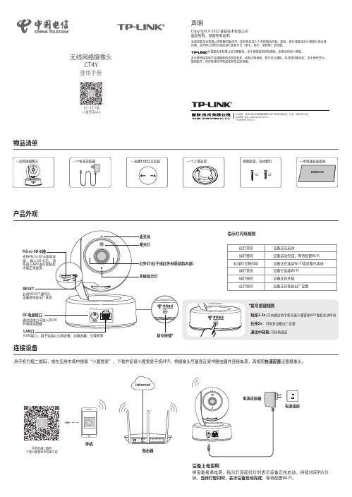
物品清单一个电源适配器产品外观连接设备电源插座将设备接通电源,指示灯亮起红灯时表示设备正在启动,持续时间约1分钟。
当绿灯慢闪时,表示设备启动完成,等待配置Wi-Fi。
设备上电说明路由器用手机扫描二维码,或在应用市场中搜索“小翼管家”,下载并安装小翼管家手机APP。
将摄像头尽量靠近家中路由器并连接电源,再按照快速配置设置摄像头。
手机手机扫描二维码下载小翼管家手机客户端扫一扫下载小翼管家APP声明未经普联技术有限公司明确书面许可,任何单位或个人不得擅自仿制、复制、誊抄或转译本手册部分或全部内容,且不得以营利为目的进行任何方式(电子、影印、录制等)的传播。
为普联技术有限公司注册商标。
本手册提及的所有商标,由各自所有人拥有。
本手册所提到的产品规格和资讯仅供参考,如有内容更新,恕不另行通知。
除非有特殊约定,本手册仅作为使用指导,所作陈述均不构成任何形式的担保。
Copyright © 2022 普联技术有限公司 版权所有,保留所有权利公司地址:深圳市南山区深南路科技园工业厂房24栋南段1层、3-5层、28栋北段1-4层 公司网址: 7103504509 REV1.0.1无线网络摄像头CT4Y使用手册有毒有害物质含量声明部件名称PCB PCBA焊点元器件(含模块)金属结构件塑胶结构件纸质配件玻璃光盘线缆铅(Pb)及其化合物○:表示该有害物质在该部件所有均质材料中的含量均在GB/T 26572规定的限量要求以下。
本表格依据SJ/T 11364的规定编制。
表示该有害物质至少在该部件的某一均质材料中的含量超出GB/T 26572规定的限量要求。
(但该项目仅在库存或已加工产品中有少量应用,且按照计划正在进行环保切换,切换后将符合上述规定。
):安装设备本产品可直接放置于桌面,也可吊顶安装,本手册介绍吊顶安装方法。
参照下图示意,将螺钉定位孔标贴粘贴于天花板,然后按照定位标贴打出底孔并塞入塑胶胀管,最后以自攻螺钉固定上墙支架位置。
Honeywell摄像头安装指南说明书
Honeywell CameraInstallation Guide6S S L.L.C.B r y a n t A v e N-B r o o k l y n P a r k-M N55444U S AT e l:+1-651-233-0977E-m a i l:i n f o@6s s.c oW e b:w w w.6s s.c oD e c e m b e r2019T ABLE OF C ONTENTS1.I NTRODUCTION (4)2.G ETTING S TARTED (5)2.1.System Requirements (5)2.2.System Introduction (5)3.I NSTALLATION OF O NVIF D EVICE M ANAGER (6)3.1.Onvif Device Manager Setup (6)3.2.Starting Onvif Device Manager (8)4.H ONEYWELL I NTEGRATION WITH M ILESTONE (10)4.1.Setup Wizard (10)4.2.Management Client Interface (12)4.3.Smart Client Interface (14)T ABLE OF F IGURESFigure 1: 6SS LPR Edge base Architecture (5)Figure 2: Run wizard (6)Figure 3: Missing .NET Framework (6)Figure 4: Onvif Device Manager Setup (7)Figure 5: Destination folder (7)Figure 6: Installation Button (8)Figure 7: Windows Firewall alert (8)Figure 8: Onvif device list (9)Figure 9: LPR Plugin Setup Folder (10)Figure 10: LPR Setup Wizard (10)Figure 11: 6SS LPR Client Installation Folder (11)Figure 12: 6SS LPR Client Installation Setup (11)Figure 13: Honeywell LPR- SQL Server (12)Figure 14: Honeywell LPR- Camera Settings (12)Figure 15: Honeywell LPR- License Settings (13)Figure 16: Honeywell LPR- Alerts Settings (13)Figure 17: Milestone Live Interface (14)Figure 18: Milestone Alarm Interface (14)Figure 19: Milestone Honeywell LPR Interface (15)1.I NTRODUCTIONThis document is intended to provide a full installation guide of Honeywell Camera and its integration with Milestone XProtect.For this purpose, Onvif Device Manager (ODM) is installed and used as a tool to read all the detected events from Honeywell camera, save them into SQL database, and in turn pushing these metadata into Milestone Smart Client.Honeywell LPR Main Features•On-board ANPR camera•Fully integrated with all Milestone XProtect versions•View Live Detection from the Camera•Filter through LPR history based on various criteria•One click data Excel/PDF Export•Alarm Hotlist capabilities•Auto data retention period handling2.G ETTING S TARTED2.1.System Requirements•Windows OS 8 or above•SQL Server 2012 or above•Onvif Device Manager v2.2.250 or above•Milestone XProtect Management Client (2016 or above)•Milestone XProtect Smart Client (2016 or above)2.2.System IntroductionThe server part of the system consists of 2 main components: Management and LPR servers. Each LPR system contains only one Management se rver, and one or more LPR servers, depending on the project size and the system’s distributed architecture. Both processes can be installed and ran on the same server, but each with its own configuration. The machine has to be licensed first before doing anything on the LPR system after the installation. Below is a figure describing the architecture of the system.1.On-Board ANPR Cameras multi-streaming to LPR server and recording servers.2.The streaming videos will flow to the recording server.3.The LPR server will communicate with the On-Board ANPR cameras to retrievethe recognized data, then will parse this upcoming data to the SQL server.4.Store results in SQL or any other database, and trigger alarms if any.5.Send results and display on Smart Client.F IGURE 1:6SS LPR E DGE BASE A RCHITECTURE3.I NSTALLATION OF O NVIF D EVICE M ANAGER3.1.Onvif Device Manager SetupDownload onvifdm.msi setup-file using the following link (/projects/onvifdm/).Right-click odm-v2.2.250 → Click Insta ll → Run onvifdm.msi.F IGURE 2:R UN WIZARDSetup Wizard will check if Microsoft .NET Framework 4 is installed o n the computer, if not click “Yes” to install it.F IGURE 3:M ISSING .NET F RAMEWORKWindows User Account Control may ask for permission, click yes to continue with the installation.F IGURE 4:O NVIF D EVICE M ANAGER S ETUPChoose the destination folder and click Next, then choose Install to start the installation.F IGURE 5:D ESTINATION FOLDERF IGURE 6:I NSTALLATION B UTTONTo complete the ONVIF Device Manager Installation process,3.2.Starting Onvif Device ManagerLaunch ONVIF Device Manager from the desktop or via the Start menu.During the first launch, Windows Firewall may ask for permission to open access to the network for onvifdm.exe as shown in Figure 7, click “Allow access”.F IGURE 7:W INDOWS F IREWALL ALERTAfter ONVIF Device Manager has been launched, the Honeywell camera is automatically detected and displayed in the device list on the left. If the device has not been detected automatically, check the connection and click Refresh as shown in Figure 8.F IGURE 8:O NVIF DEVICE LIST4.H ONEYWELL I NTEGRATION WITH M ILESTONE4.1.Setup WizardUnzip the Release folder and open to run the setup wizard for the LPR plugin.F IGURE 9:LPR P LUGIN S ETUP F OLDERF IGURE 10:LPR S ETUP W IZARDChoose the path to where the LPR plugin folder will be created as shown in Figure 11. Click next to continue and the setup will be installed as shown in Figure 12.F IGURE 11:6SS LPR C LIENT I NSTALLATION F OLDERF IGURE 12:6SS LPR C LIENT I NSTALLATION S ETUP4.2.Management Client InterfaceOpen Milestone XProtect Management Client then click “HONEYWELL LPR” under MIP Plugins as shown in Figure 13.Error! Reference source not found.In the first tab enter the server name or IP address in case the SQL Server is installed on a different device otherwise you can keep it blank (local host).F IGURE 13:H ONEYWELL LPR-SQL S ERVERThen, you need to specify Honeywell camera settings for first time use by entering the camera IP address and port number, click “Set Connection Info” to save your settings.F IGURE 14:H ONEYWELL LPR-C AMERA S ETTINGSAs for the LPR license, click “Get Computer ID” button and send to *********** the issued product ID with the number of licenses needed to activate the LPR. Upon receiving the license file, click “Import License” button to import the latter.Note that for each camera used a license is required. The license is paid once with no expired date, with a yearly optional upgrade (18 % of the license fee for each camera) for any additional features, maintenance, and enhanced versions.F IGURE 15:H ONEYWELL LPR-L ICENSE S ETTINGSThe last tab is for alerts. Here you can specify the plate number you want to fire an alarm for when detected by the camera, either as a blacklisted or whitelisted. You can also attach an event for this alarm in order to trigger a certain action. Use the button “Add Alert” to activate the alarm.F IGURE 16:H ONEYWELL LPR-A LERTS S ETTINGS4.3.Smart Client InterfaceOpen Milestone XProtect Smart Client. In the live tab select your intended camera as shown in the bottom right corner of Figure 17.When the camera detects license plate number, the latter will be shown as a snapshot of the plate number in the right panel above the button “Select Camera”.F IGURE 17:M ILESTONE L IVE I NTERFACEAll the alerts previously defined in the management client are shown in the “Alarm Manager” tab with a red flag indicating the number of alarms fired as shown in Figure 18. If you click on a certain alarm the live and recording videos will be shown a long with the alarm’s information.F IGURE 18:M ILESTONE A LARM I NTERFACEIn the “Honeywell LPR” tab you can check all the LPR events captured by which camera, in which category and country, at what confidence level detected at a certain date along with the plate number and its image. You can use the filters shown in the right panel of Figure 19 as well as to export the listed events to excel file.When you click on an event line you can use the bottom right video to play back the video frame from the first moment the plate number is captured.F IGURE 19:M ILESTONE H ONEYWELL LPR I NTERFACE。
Hikvision 移动网络摄像头安装指南说明书
·Mobile Network CameraInstallation GuideLegal Information©2022 Hangzhou Hikvision Digital Technology Co., Ltd. All rights reserved.About this ManualThe Manual includes instructions for using and managing the Product. Pictures, charts, images and all other information hereinafter are for description and explanation only. The information contained in the Manual is subject to change, without notice, due to firmware updates or other reasons. Please find the latest version of this Manual at the Hikvision website (https:///).Please use this Manual with the guidance and assistance of professionals trained in supporting the Product.Trademarksand other Hikvision’s trademarks and logos are the properties of Hikvision in various jurisdictions. Other trademarks and logos mentioned are the properties of their respective owners.DisclaimerTO THE MAXIMUM EXTENT PERMITTED BY APPLICABLE LAW, THIS MANUAL AND THE PRODUCT DESCRIBED, WITH ITS HARDWARE, SOFTWARE AND FIRMWARE, ARE PROVIDED “AS IS” AND “WITH ALL FAULTS AND ERRORS”. HIKVISION MAKES NO WARRANTIES, EXPRESS OR IMPLIED, INCLUDING WITHOUT LIMITATION, MERCHANTABILITY, SATISFACTORY QUALITY, OR FITNESS FOR A PARTICULAR PURPOSE. THE USE OF THE PRODUCT BY YOU IS AT YOUR OWN RISK. IN NO EVENT WILL HIKVISION BE LIABLE TO YOU FOR ANY SPECIAL, CONSEQUENTIAL, INCIDENTAL, OR INDIRECT DAMAGES, INCLUDING, AMONG OTHERS, DAMAGES FOR LOSS OF BUSINESS PROFITS, BUSINESS INTERRUPTION, OR LOSS OF DATA, CORRUPTION OF SYSTEMS, OR LOSS OF DOCUMENTATION, WHETHER BASED ON BREACH OF CONTRACT, TORT (INCLUDING NEGLIGENCE), PRODUCT LIABILITY, OR OTHERWISE, IN CONNECTION WITH THE USE OF THE PRODUCT, EVEN IF HIKVISION HAS BEEN ADVISED OF THE POSSIBILITY OF SUCH DAMAGES OR LOSS.YOU ACKNOWLEDGE THAT THE NATURE OF THE INTERNET PROVIDES FOR INHERENT SECURITY RISKS, AND HIKVISION SHALL NOT TAKE ANY RESPONSIBILITIES FOR ABNORMAL OPERATION, PRIVACY LEAKAGE OR OTHER DAMAGES RESULTING FROM CYBER-ATTACK, HACKER ATTACK, VIRUS INFECTION, OR OTHER INTERNET SECURITY RISKS; HOWEVER, HIKVISION WILL PROVIDE TIMELY TECHNICAL SUPPORT IF REQUIRED.YOU AGREE TO USE THIS PRODUCT IN COMPLIANCE WITH ALL APPLICABLE LAWS, AND YOU ARE SOLELY RESPONSIBLE FOR ENSURING THAT YOUR USE CONFORMS TO THE APPLICABLE LAW. ESPECIALLY, YOU ARE RESPONSIBLE, FOR USING THIS PRODUCT IN A MANNER THAT DOES NOT INFRINGE ON THE RIGHTS OF THIRD PARTIES, INCLUDING WITHOUT LIMITATION, RIGHTS OF PUBLICITY, INTELLECTUAL PROPERTY RIGHTS, OR DATA PROTECTION AND OTHER PRIVACY RIGHTS. YOU SHALL NOT USE THIS PRODUCT FOR ANY PROHIBITED END-USES, INCLUDING THE DEVELOPMENT OR PRODUCTION OF WEAPONS OF MASS DESTRUCTION, THE DEVELOPMENT OR PRODUCTION OF CHEMICAL OR BIOLOGICAL WEAPONS, ANY ACTIVITIES IN THE CONTEXT RELATED TO ANY NUCLEAR EXPLOSIVE OR UNSAFE NUCLEAR FUEL-CYCLE, OR IN SUPPORT OF HUMAN RIGHTS ABUSES.IN THE EVENT OF ANY CONFLICTS BETWEEN THIS MANUAL AND THE APPLICABLE LAW, THE LATTER PREVAILS.Regulatory InformationFCC InformationPlease take attention that changes or modification not expressly approved by the party responsible for compliance could void the user’s authority to operate the equipment.FCC ComplianceThis equipment has been tested and found to comply with the limits for a Class A digital device, pursuant to part 15 of the FCC Rules. These limits are designed to provide reasonable protection against harmful interference when the equipment is operated in a commercial environment. This equipment generates, uses, and can radiate radio frequency energy and, if not installed and used in accordance with the instruction manual, may cause harmful interference to radio communications. Operation of this equipment in a residential area is likely to cause harmful interference in which case the user will be required to correct the interference at his own expense.FCC ConditionsThis device complies with part 15 of the FCC Rules. Operation is subject to the following two conditions:1.This device may not cause harmful interference.2.This device must accept any interference received, including interference that may causeundesired operation.EU Conformity StatementThis product and - if applicable - the supplied accessories too are marked with "CE" andcomply therefore with the applicable harmonized European standards listed under the EMC Directive 2014/30/EU, the LVD Directive 2014/35/EU, the RoHS Directive 2011/65/EU.2012/19/EU (WEEE directive): Products marked with this symbol cannot be disposed of as unsorted municipal waste in the European Union. For proper recycling, return this product to your local supplier upon the purchase of equivalent new equipment, or dispose of it at designated collection points. For more information see: 2006/66/EC (battery directive): This product contains a battery that cannot be disposedof as unsorted municipal waste in the European Union. See the product documentation for specific battery information. The battery is marked with this symbol, which may include lettering to indicate cadmium (Cd), lead (Pb), or mercury (Hg). For proper recycling, return the battery to your supplier or to a designated collection point. For more information see: Industry Canada ICES-003 ComplianceThis device meets the CAN ICES-3 (A)/NMB-3(A) standards requirements.Applicable ModelsSymbol ConventionsSafety Instructions●Proper configuration of all passwords and other security settings is the responsibility of theinstaller and/or end-user.●In the use of the product, you must be in strict compliance with the electrical safety Inputvoltage should meet limited power source or PS2 requirements regulations of the nation and region. Please refer to technical specifications for detailed information.●Input voltage should meet limited power source or PS2 requirements according to theIEC60950-1 or IEC 62368-1 standard. Please refer to technical specifications for detailedinformation.●Do not connect several devices to one power adapter as adapter overload may cause over-heating or a fire hazard.●Please make sure that the plug is firmly connected to the power socket.●If smoke, odor or noise rise from the device, turn off the power at once and unplug the powercable, and then please contact the service center.TABLE OF CONTENTSChapter 1 Packing List and Cable Description (1)Packing List (1)Cable Description (3)Chapter 2 Installation (4)Installation Requirements (4)2.1.1 Installation Position Requirements (4)2.1.2 Installation Surface Requirements (4)2.1.3 Water Proof Requirements (4)Vertical Installation (4)2.2.1 Vertical Installation Method 1 (4)2.2.2 Vertical Installation Method 2 (7)Horizontal Installation (11)Chapter 3 Angle Adjustment (15)Adjust With Wrench (15)Adjust the Body of the Camera (16)Chapter 1 Packing List and Cable DescriptionBefore You BeginBefore unboxing, check if the package is intact. Refer to the list to make sure that all the assembly parts are included. The 3 types of packing lists of the mobile network camera is shown below.Packing ListThere are 3 type of cable available, differing on their support for power, alarm and internet interface. Please choose according to your actual need.Packing List of Type I CameraNoPicture Name Number 1Camera 12Wrench 13ST4.8×25 Screws 1 4QSG 1 5Tape 3 6Water Proof Suit(Only Available forRJ45 Cable)1Packing List of Type II CameraNoPicture Name Number 1Camera 12Wrench 13ST4.8×25 Screws 1 4QSG15Tape 3NoPicture Name Number 1Camera 12Wrench 13ST4.8×25 Screws 14QSG 1 5Tape 3Cable DescriptionThere are 3 types of cables for the network camera, as shown in the following figures. Please refer to the relevant instructions according to the physical equipment.Rj45 Cable4 Core Cable6 Core Cable ● Power Interface: the camera supports 9V-36V power supply. Please connect the positive and negative poles of the power supply correctly.● Internet Interface: network signal output.● Alarm Interface: support alarm input and output.Chapter 2 InstallationInstallation RequirementsBefore you beginPuncture a hole on the body of the vehicle for the cable of the camera to go through. Match the sheet metal fixed support with the hole when installing the camera.The camera can be installed both horizontally and vertically, though the later is preferred. Typically, horizontal installation is recommended for the police vehicle, and the vertical installation is recommended for school bus and ambulance.To install the camera vertically, two requirements should be met for the best capture performance and the ease of installation:●The height of installation should be between 1-1.6 m●The surface of installation should be vertical to the ground.When both requirements can be met, refer to 2.2.1 Vertical Installation Method 1. If not and camera is to be installed on a tilted surface, refer to 2.2.2 Vertical Installation Method 2. On the tilted surface, the camera requires further calibration of its angle.For the stability of the camera, two further requirements of the material of the surface of the installation should be met:●When the camera is installed on the sheet metal, its thickness should be more than 1.2 mm. Ifthe thickness is bellow this number, it is recommended to strengthen the sheet metal with a reinforcing plate.●When the camera is installed on a plastic surface, it is recommended to strengthen the surfacewith a reinforcing plate.The throwing line of the camera should not be exposed outside of the vehicle. It is recommended to get the cable connection part water-proof treatment.Vertical InstallationSince the installation process of cameras with differing cables are the same, we take one type to illustrate the installation process.Use the hexagon wrench in the package to unfasten the two the screws at the back of the camera.Unfasten the ScrewsTake off the sheet metal from the camera, and the rubber seal of the cable from the sheet metal.Take Off the Sheet Metal and Rubber SealVertically place the sheet metal fixed support on the place where the camera is to be installed, and then fix it with the screw.Fix the Sheet Metal Fixed SupportGuide the cable through the cable hole, seal the hole with the rubber seal, and install the camera back to the sheet metal fixed support.Reinstall the Camera to the Fixed SupportTighten the two screw on the back of the camera.Tighten the ScrewsLoose the screw on the two sides of the camera with the hexagon wrench, adjust the angle of the camera for the best vision and tighten the two fixation screw to avoid wobble.Adjust the Angle of the CameraUse the hexagon wrench in the package to unfasten the two the screws at the back of the camera.Unfasten the ScrewsTake off the sheet metal from the camera, and the rubber seal of the cable from the sheet metal.Take Off the Sheet Metal and Rubber SealVertically place the sheet metal fixed support on the place where the camera is to be installed, but do not tighten the screw to the end.Fix the Sheet Metal Fixed SupportGuide the cable through the cable hole, seal the hole with the rubber seal.Reinstall the Camera to the Fixed SupportInstall the camera back to the sheet metal fixed support, adjust and record the angle of the camera for best vision. For details, see Chapter 3 Angle Adjustment.Adjust the Angle of the CameraTighten the two screw on the back of the camera.Tighten the ScrewsAgain guide the cable through the cable hole, seal the hole with the rubber seal.Organize the CableRe-install the camera back to the sheet metal fixed support, adjust the angle of inclination of the camera to the angle recorded, and tighten the two fixation screw to avoid wobble.Reinstall the CameraHorizontal InstallationUse the hexagon wrench in the package to unfasten the two the screws at the back of the camera.Unfasten the ScrewsTake off the sheet metal from the camera, and the rubber seal of the cable from the sheet metal.Take Off the Sheet Metal and Rubber SealHorizontally place the metal sheet on the position of installation and then fasten the screws.Guide the cable through the cable hole, seal the hole with the rubber seal, and install the camera back to the sheet metal fixed support.Install the Camera to the Fixed SupportTighten the two screw on the back of the camera.Tighten the ScrewsLoose the screw on the two sides of the camera, adjust the angle of the camera for the best vision, and tighten the two fixation screw to avoid wobble.Adjust the Angle of the CameraChapter 3 Angle AdjustmentAdjust With WrenchThe angle of the camera can be adjusted in 2 ways: adjust with the wrench and adjust the angle that it is installed on the surface of the vehicle. If the installation surface is vertical to the ground, then no need for adjusting the body of the camera.Loose the screw on the two sides of the camera with the hexagon wrench.Adjust the Angle With the WrenchAdjust the angle of the camera for the best vision. The range is 80°and the scales differ by 10°. After the adjustment, tighten the two fixation screw to avoid wobble.Range And ScaleAdjust the Body of the CameraWhen installed on a tilted surface, loosen the two screws at the back of the camera and adjust the body of the camera before adjusting the camera itself.Loosen the ScrewsThe metal sheet can be opened up to 30° and both sides are supported.Range of the Inclination AngleAdjust the vertical vision by the moving the camera around the screw in the metal sheet.Adjust the Vertical VisionUD30023B 0。
BL-C101 和 BL-C121 网络摄像头安装指南说明书
Installation GuideModel No.BL-C101(Wired Type)BL-C121(Wireless/Wired Type)This manual is written for both the BL-C101 (Wired Type) and BL-C121 (Wireless/Wired Type). Available features and operations vary slightly depending on the model. You can confirm the model no. of your camera by checking the model no. printed on the front of the camera.Model number suffixes (“A”, “CE”, and “E”) are omitted from the following model numbers shown in this document, unless necessary.BL-C101A, BL-C101CE, BL-C101E, BL-C121A, BL-C121CE, BL-C121EPlease read the included Important Information before proceeding.Complete Operating Instructions and all other documentation can be found on the included CD-ROM.•This document (Installation Guide) explains how to physically connect the camera to the power supply and network, as well how to mount or place thecamera for regular use.•The Setup Guide describes how to set up the camera so that it can be accessed using a PC.•Refer to the Operating Instructions on the CD-ROM for details regarding the camera’s features.•Refer to the Troubleshooting Guide on the CD-ROM if you have any problems configuring or using the camera.Abbreviations•UPnP is the abbreviation for “Universal Plug and Play”.•The Network Camera is referred to as “the camera” in this document.•The Setup CD-ROM is referred to as “the CD-ROM” in this document.Installation Procedure OverviewThe following is an overview of the steps required to install and setup the camera. All steps are explained in this document unless otherwise noted.Preparation1.Confirm the following items are included in the camera’s packaging.2.You will need the following additional items to install and configure the camera.– a PC (see the system requirements in the Important Information document)–For BL-C101: 2 LAN cables (CAT-5 straight cable)For BL-C121: a LAN cable (CAT-5 straight cable)– a routerPreparationConfirm that you have all the items required for installation.Camera DiagramMake sure you know the names of the camera’s physical features.ConnectionsConnecting the camera to your network and to the power outlet.SetupSetting up the camera(described in the included Setup Guide). This involves configuring the camera so that it can be accessed from a PC.MountingMounting or placing the camera.© Panasonic System Networks Co., Ltd. 2008PNQX1566XA KK0908CM2020Please read this document before using the product, and save this document for futureCamera DiagramsConnectionsConnect the camera to your router and to the power outlet as described below.•Before proceeding, confirm that your PC is connected to your router and can access the Internet. Also confirm that your router’s UPnP™ feature is enabled. (Most routers have UPnP™ turned off by default.) Refer to the operating instructions included with your router or to the Panasonic Network Camera website (/pcc/support/netwkcam/) for more information.BL-C101•BL-C121BL-C101BL-C121FACTORY DEFAULTRESET buttonWIRELESS/WIREDswitchLAN portSerial number labelStand/Tripod MountingHoleExternal I/O interfaceDC IN jackHook for AC adaptorcord1unit.21Confirm that the WIRELESS/WIRED switchon the side of the camera is set to WIRED.2Connect the LAN cable to the camera andthe router.3Connect the AC adaptor cord to the DC INjack.4Plug the AC adaptor into the power outlet.•Confirm that the indicator turns greenafter about 1 minute. If it does not turngreen, see 1.2 Camera Indicator Issues in•easily accessible.•Use only specified Panasonic AC adaptor(Order No. PQLV206Y for BL-C121A,PQLV216CE1Z for BL-C121CE, BL-C121E).•The camera may become warm. This isnormal.After the camera’s indicator turns green, you may set up the camera. Continue by following the procedure described in the included Setup Guide.•If the indicator does not turn green, see 1.2 Camera Indicator Issues in the Troubleshooting Guide on the included CD-ROM.23For BL-C121: Notes About Wireless CommunicationThe radio wave range may decrease depending on the surrounding environment or existence of obstacles. If obstacles such as the following are placed between a camera and a router, radio waves will weaken. Therefore, even if the distance between the camera and router is short, the frame rate may decrease or images may not be displayed.•A metallic door or shutter•A wall with an insulation material that contains aluminum foil •A wall made of tin•A wall made of concrete, stone or brick •Fireproof glass•Several walls separated by open space •A steel shelfIn the example below, wireless communication between the camera and the wireless router is impaired due to steel doors or reinforced concrete walls between the camera and the wireless router.Circuit Diagram ExampleCaution•The external I/O interface is not capable of connecting directly to devices that require large amounts of current. In some cases, acustom interface circuit (customer-provided) may have to be used.Serious damage to the camera may result if a device that exceedsits electrical capability is connected to the external I/O interface.•Low voltage/current circuits and high voltage/current circuits areused in the camera circuit. All wiring should be performed by a qualified electrician. Incorrect wiring could damage the camera and cause a fatal electric shock.•External devices connected to the camera’s output terminals cannot be controlled in the event of a network error or failure. Keep this in mind when connecting door locks, heat-emitting devices, or otherdevices that may be dangerous if they cannot be controlled. (BL-C121 only)Note•If excessive force is used when disconnecting wires with pointed objects from the external I/O interface, terminals may become damaged or the interface may be pushed inside the camera body and become unusable.Mounting the Camera•The camera illustrations in this document depict the BL-C121. Caution•Do not drive the screws into a soft material. Drive the screws into a secure area of the wall, such as a wall stud, otherwise the camera may fall and be damaged.•Make sure you attach the safety wire when mounting the camera, to prevent the camera from falling.Note•Use screws that are appropriate for the material of the wall.•The included screws are for use with wooden walls only.•The camera is intended for indoor use only and should not bemounted outdoors.•To ensure that camera images are displayed properly, do not mount the camera on an incline. Mount the camera so that it isperpendicular to the floor. Do not mount the camera upside down. Flexible Stand Mount1.Loosen the position lock located on the rear side of the flexible stand.2.Turn the mounting screw to attach the camera.3.Adjust the angle, then fasten the position lock.Tripod Mount•Do not use a tripod screw with a thread of 6 mm (1/4 inch) or more.This may damage the stand/tripod mounting hole.•The camera cannot be mounted depending on the shape of thecamera platform.Ceiling/Wall Mount1.Secure the safety wire to the camera using screw B (included) andwasher S (included).•Make sure you attach the safety wire when mounting the camera, to prevent the camera from falling.2.Connect a LAN cable to the camera.•Insert the LAN cable until it clicks into to place.3.Mount the flexible stand firmly to the ceiling or wall with screw A(included).•Do not drive the screws into a soft material. Drive the screws into a secure area of the wall, such as a wall stud, otherwise the camera may fall and be damaged.•Use screws that are suited for the type of material the camera is mounted to.•Allow sufficient space between the ceiling or wall and the flexible stand to turn the position lock.•Make sure the flexible stand is firmly mounted on a wall or ceiling stud (25mm [1inch] and greater) etc. When there is no stud, apply a board on the other side of the ceiling or wall to make sure the camera does not drop.4.Loosen the position lock located on the rear side of the flexible stand,5.6.Connect all necessary cables (AC adaptor, LAN, etc.) to the camera,dress the cables neatly, and secure with tape (customer-provided).7.Secure the safety wire to the ceiling or wall using screw A (included)and washer L (included).•Leave some slack in the safety wire, as shown.•Make sure the safety wire is firmly mounted on a wall or ceiling stud (25 mm [1 inch]and greater) etc. When there is no stud, apply a board on the other side of the ceilingor wall to make sure the camera does not drop.When mounting on a mortar or concrete surface•Prepare anchors for 4 mm (3/16 inch) diameter screws for mounting.1.Place the flexible stand on the ceiling or wall where you plan to mountthe flexible stand and mark the points where you are going to makeholes.2.Make holes with an electric drill. Insert anchors (customer-provided)into the holes and use a hammer to make them flush with the wall.•Mortar ceilings or walls break easily when drilling. Be careful of pieces of mortarwhich may become loose and fall.3.Mount the flexible stand using the screws.For BL-C101 Only: Connecting to the power transfer unit8.Connect a LAN cable to the power transfer unit and to the switchinghub, router, etc.•The power transfer unit can be fixed in place with 2 pieces from screw A (included)(4 mm x 20 mm [3/16 inch x 13/16 inch]).9.Connect a LAN cable from the camera to the power transfer unit.10.Connect the AC adaptor to the power transfer unit and plug the otherend into the power outlet.•The camera will activate.NWallN Ceiling NN N WallN Ceiling N WallN Ceiling N Wall4。
监控摄像头安装手册
监控摄像头安装手册一、引言监控摄像头作为一种重要的安防设备,在现代社会中起着越来越关键的作用。
为了正确、有效地安装和使用监控摄像头,本手册将为您提供详细的安装指南。
二、准备工作1. 确定安装地点:在选择安装位置时,应考虑到监控范围、光线状况、目标高度等因素。
合理选择安装地点可以达到最佳的监控效果。
2. 确认设备和材料:除了摄像头本身外,您还需要准备所需的支架、电源适配器、网络线等设备和材料。
三、安装步骤1. 安装支架:根据您选择的安装地点,固定支架并确保其稳固。
支架的稳定性对于摄像头的稳定和清晰画面起着重要作用。
2. 连接电源:将电源适配器连接到摄像头,确保电源线和适配器连接牢固,并将电源插头插入电源插座。
检查电源连接是否牢固,确保正常供电。
3. 连接网络:如果您使用的是网络摄像头,将网络线插入摄像头的网络接口,并将另一端连接到网络设备(如路由器)的网络端口。
4. 调整角度与焦距:根据实际需要,调整摄像头的角度和焦距,以确保监控范围清晰可见,并满足实际需求。
5. 安装调试:确认以上步骤完成后,接通电源,观察监控摄像头是否正常工作。
如有问题,可查阅设备说明书,或联系厂家技术支持。
四、注意事项1. 电源安全:安装前确保电源适配器和插座无损坏,避免短路和触电的风险。
在安装过程中,确保电源线不被压弯或拉扯,以保证正常供电。
2. 防水防尘:如果您的摄像头将安装在室外或高湿度环境中,请选择具有防水防尘功能的摄像头,并注意将连接线缠绕在防护套管内,以保证设备的正常运行。
3. 安全隐私:在进行监控设备的安装,请遵守相关法律法规,确保监控摄像头的使用不侵犯他人的隐私权。
4. 定期维护:安装完毕后,定期检查设备运行状态与清洁镜头,以保证监控摄像头的正常工作。
五、结语本手册为您提供了监控摄像头安装的详细指南。
正确安装和使用监控摄像头,不仅可以提高安全性,还可以提供有效的监控功能。
希望本手册能够帮助您顺利完成监控摄像头的安装,保障您的安全需求。
摄像头说明书
摄像头说明书首先感谢光临魅族小铺!现在都是电子时代,我们崇尚的是绿色,快捷,和简便。
1.把摄像头的USB接口接到主机后面的USB接口孔里去。
嘿嘿这个应该知道什么叫做USB 接口把。
如果这个都不知道,偶无语了。
2.摄像头的麦克风的接口接到台式电脑主机后面的粉红色孔里注意大部分的主机背后的粉红色的孔是麦克风的接口孔不排除有的主机的麦克风接口不是粉红色的。
笔记本电脑的话,麦克风的接口边上应该有个麦克风形状的图标(再注意: 如果您用了音响,请拔掉音响在主机上的接头,先别听不听到声音现在是教您怎么使用麦克风)麦克风接口插好后就能检测麦克风是不好的按我说的步骤来做哦:点电脑桌面最左下方开始程序附件娱乐录音机1 打开录音机有的朋友会说当我视频聊天的时候麦克风是没有声音的,这个也是您没设置好: 有的买家说录音上没有音波,其实不是没有的只是感应的有点小,这个是和您的声卡驱动的好坏有关系的点电脑桌面最右下方有一个小喇叭音量的图标双击后会弹出这样的图像主音量你拉到最大这样麦克风的音量就能放大到最大麦克风的音量不是由麦克风的控制的而是纯粹由您的电脑系统音频驱动的好坏决定的。
这个误区希望朋友们一定要知道!接下如图示点选项属性然后会弹出这样的界面点录音麦克风前面的勾勾一定要勾上、然后点确定接下来会弹出录音控制如图示接下来点高级麦克风加强前面的勾勾也勾上这样就加强了麦克风的音量!您就再也不会说麦克风的音量小了哦,(*^__^*)QQ上视频安装语音(麦克风)测试:打开一个QQ聊天面板,点击语音后面的三角箭头,里面有个设置:(如下图)打开设置,点击里面的点击测试音频设备:(对着话筒说话,自己的电脑音箱有声音才算OK)视频测试:开一个QQ聊天面板,点击视频后面的三角箭头,里面有个设置:(下图打开设置,视频设备选择USB视频设备如果光线太强,色彩太暗,可以点击画质调节,进行各项调节,如下图:QQ 上设置基本完成!!还有的摄像头带有夜视灯的,USB线上会有个滚轮,很多朋友会人为是麦克风的音量控制的。