达美盛-AutoCAD Plant3D三维工厂设计方案建议书
Autodesk Plant Solutions AutoCAD Plant 3D性能优化指南说明书
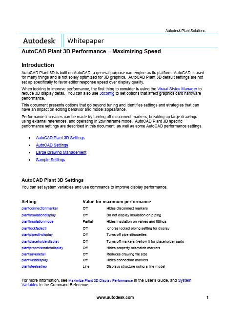
Autodesk Plant Solutions WhitepaperAutoCAD Plant 3D Performance – Maximizing SpeedIntroductionAutoCAD Plant 3D is built on AutoCAD, a general purpose cad engine as its platform. AutoCAD is used for many things and is not solely optimized for 3D graphics. AutoCAD Plant 3D default settings are not set up specifically to favor editor response speed over display quality.When looking to improve performance, the first thing to consider is using the Visual Styles Manager to reduce 3D display detail. You can also use 3dconfig to set options that affect graphics card hardware performance.This document presents options that go beyond tuning and identifies settings and strategies that can have an impact on editing behavior and model appearance.Performance increases can be made by turning off disconnect markers, breaking up large drawings using external references, and operating in 2dwireframe mode. AutoCAD Plant 3D specific performance settings are described in this document, as well as some AutoCAD performance settings.∙AutoCAD Plant 3D Settings∙AutoCAD Settings∙Large Drawing Management∙Sample SettingsAutoCAD Plant 3D SettingsYou can set system variables and use commands to improve display performance.Setting Value for maximum performanceplantconnectionmarker Off Hides disconnect markersplantinsulationdisplay Off Do not display insulation on pipingplantinsulationmode Partial Hides insulation on valves and fittingsplantlockfadectl Off Ignores locked piping setting for display plantpipesilhdisplay Off Turns off pipe silhouettesplantplaceholderdisplay Off Turns off markers (yellow !) for placeholder parts plantpropmismatchdisplay Off Hides property mismatch markersplantsavedetail Off Reduces drawing file sizeplantwelddisplay Off Hides connection markersplantsteelsetrep Line Displays structure using a line modelFor more information, see Maximize Plant 3D Display Performance in the User’s Guide, and System Variables in the Command Reference.You can close AutoCAD Plant 3D palettes that you are not using when working in the model. For example, closing the Data Manager can improve performance, especially when editing. You can also close Project Manager to improve performance. For best results close the palette, do not Auto-Hide.AutoCAD SettingsThere is no single best AutoCAD setting for performance, because some settings are designed to disable features that you need to select and edit. In general, the settings identified here are intended to maximize browsing speed.The most significant choice is between 2D and 3D view modes. 2D modes can display 3D objects that look similar to 3D wireframe, but the modes use a significantly different redraw database. The 3D redraw database is designed for quality and response, but not scalability. In practical terms, this means that in 3D view modes, performance deteriorates faster as the model in the display gets larger. Changing to 2D wireframe with silhouettes off can significantly improve performance.dispsilh=0, isolines=4 dispsilh=1, Isolines=0If you turn off dispsilh to improve performance in wireframe, you should set isolines to 4. Piping also uses plantpipesilhdisplay, which displays silhouettes for tube segments when dispsilh is off.For more information, see Control the Visual Style of the Plant 3D Model.Below are some of the AutoCAD system variables you can use to improve performance.AutoCAD Setting Value for maximum performancedispsilh Off Do not display silhouette edgesisolines 4 The number of contour lines per surface on objectspickfirst Off Objects are selected after the commandviewres 1 Sets the smoothness of curved objects in a 2D view savetime Zero (0) Turn off autosavevscurrent2Dwireframe Sets the fastest display modevtenable 0 Turns off smooth view transitions customerinvolvementprogram Off Turns off activity loggingIt is important to understand the impact of these settings and consider that they could cause undesired behavior. For example, turning off pickfirst speeds up browsing, but it disables the select connected parts shortcut menu. Dragging in 2dwireframe can be slower than 3dwireframe. The best performance configuration depends on how you are working with the model. Setting a low viewres speeds up dragging in 2D mode. Facetres is a similar variable that affects 3D views.You can use vtoptions to set a fast transition speed, lower the performance (fps) threshold, or disable view transitions.Other settings that are not specific to display can be used. For example, you can freeze unused layers to improve performance, instead of turning a layer off.You can also turn off features that you do not use. For example, if you do not need the properties window open, consider closing it until needed. Tracking, dynamic input, and even grips can be turned off when not used.Large Drawing ManagementBreaking up larger drawings into smaller ones using external references can significantly improve performance. For example, you can place equipment, piping, and structure into different drawings and break up large drawings by area.Sample SettingsYou can copy and paste the table below into the Command window, or create and run a LSP file. Values are also provided to restore default settings.Performance settings:(command "plantconnectionmarker" "0")(command "plantinsulationdisplay" "0")(command "plantinsulationmode" "p")(setvar "plantpipesilhdisplay" 0)(setvar "plantpropmismatchdisplay" 0)(command "plantplaceholderdisplay" "0")(setvar "plantwelddisplay" 0)(setvar "plantlockfadectl" 0)(setvar "plantsavedetail" 0)(command "plantsteelsetrep" "L")(setvar "dispsilh" 0)(setvar "isolines" 4)(setvar "pickfirst" 0)(command "viewres" "y" 1)(setvar "savetime" 0)(command "vscurrent" "2dwireframe")(setvar "vtenable" 0)(if (/= (getvar "cipmode") 0) (prompt "\nRun customerinvolvementprogram to disable.")) Default settings:(command "plantconnectionmarker" "1")(command "plantinsulationdisplay" "1")(command "plantinsulationmode" "f")(setvar "plantpipesilhdisplay" 1)(command "plantplaceholderdisplay" "1")(setvar "plantsavedetail" 1)(setvar "dispsilh" 1)(setvar "isolines" 0)(setvar "pickfirst" 1)(command "viewres" "y" 1000)(setvar "savetime" 10)(setvar "vtenable" 3)(command "vscurrent" "realistic")Autodesk, Inc.111 McInnis ParkwaySan Rafael, CA 94903USAAutodesk [and other products] are either registered trademarks or trademarks of Autodesk, Inc., in the USA and other countries. All other brand names, product names, or trademarks belong to their respective holders.© 2010 Autodesk, Inc. All rights reserved.。
浅析三维工厂设计软件Autocad Plant 3D在工厂项目中的应用

浅析三维工厂设计软件Autocad Plant 3D在工厂项目中的应用(兖矿国宏化工有限责任公司,山东 邹城 273512)李仕超摘要:介绍了三维工厂设计软件在国内外的发展情况,重点对Autocad Plant 3D软件的特点和优势进行了介绍,同时阐述了未来工厂设计的发展趋势。
关键词:三维工厂设计;Autocad Plant 3D;工厂;应用1 前言目前,随着科学技术的进步和人类思想认识的逐步提升,新兴的设计手段已越来越广泛的应用于石油、化工、机械和电子等各行各业,其中的三维软件更是如雨后春笋搬纷纷发展,它们以自身的直观、高效、精准和简捷的优势得到了业主和设计院的推崇。
传统的项目设计大多使用二维AutodCAD完成工厂设计,无法直观、精准的反映出工厂布局和设备、厂房和管道布置情况,工作效率低下,设计周期冗长繁琐,而且非常容易出错,修改起来比较麻烦,已经越来越不能适应社会的快速发展,三维工厂系统设计软件的出现使得这些难题迎刃而解。
目前在国内设计院和石化工厂使用较多的三维工厂设计软件有PDS、PDMS、Autoplant 3D和Autocad Plant 3D等,在中小型工厂项目设计中,尤以Autocad Plant 3D(以下简称P3D)发展最为迅猛,得到了设计院和业主的青睐。
2 三维软件特点简介Autocad Plant 3D是由欧特克公司开发的新兴工厂三维系统设计软件,采用MS SQL lite 大型关系数据库,软件包含了P&ID、plant 3d、cad等部分,自带了完整的以欧洲标准、美洲标准和中国国标开发的三维元件库,涵盖了从钢结构、土建、支架、设备、管道,到各种尺寸和压力等级的法兰、垫片、螺栓、螺母、三通、弯头、阀门、过滤器等管件,同时还可以根据项目需要自行添加各式各样的规格表,软件具有的特点有如下几个方面:2.1 精准显示工厂布置情况,与Auto CAD无缝衔接P3D是欧特克公司基于自家AutoCAD平台开发的三维工厂软件,能与CAD实现无缝衔接,文件本身就以DWD格式进行存储,操作命令和CAD全兼容,可随时切换到CAD工作空间进行操作。
AutoCAD Plant 3D
AutoCAD P&ID软件具有经过简化的绘图、编辑、 验证工具
报表生成、验证和设计信息交换等特性。该软件 利用验证工具进行错误检测,识别、突显和定位
能够简化和自动执行日常的P&ID任务,从而提高 工程图中的矛盾之处。提高精度,并最大限度地
生成施工文档 您可以更加轻松地从三维模型生成和共享ISO图、 正交视图和其它施工文档。可利用三维模型直接 交换信息,帮助您提高施工文档的精度和一致 性,并及时更新施工文档。
设备元素 创建、修改、管理和使用工厂模型中的设备。可 从“工具”选项板使用一个完备的标准设备库。 在该设备库中添加定制的标准件或导入Autodesk® Inventor®设备模型。
AutoCAD® P&ID 创建、修改和管理管道和设备流程
图,然后根据三维模型修改基本 P&ID数据。
Autodesk® Navisworks® 整合来自多个设计软件的模 型,可视化和共享整合后的模 型,确定碰撞和冲突。
AutoCAD® 利用全球领先的CAD工具及其中强 大灵活的特性进行设计和绘图。
Autodesk® Plant Design Suite Premium:
• AutoCAD • AutoCAD P&ID • AutoCAD Plant D • Autodesk Navisworks Simulate
Autodesk® Plant Design Suite Advanced:
• AutoCAD • AutoCAD P&ID • AutoCAD Plant D • Autodesk Navisworks Manage
4-AutoCAD Plant 3D 初级培训-Plant 3D成果输出

补充说明
• 视图生成后,点击“编辑视图”,可重新调整参与切图的模型、切图范围和视图 比例。如果P3D模型发生变化,可点击“更新视图”。 • 在图纸空间下使用AutoCAD移动命令移动视口线,可以移动视图位置。要重 设视图比例,先选择视口线,再点击下方状态栏的“解锁视口”按钮,就可以调 整视图比例。调整后最好重新锁定视口。 • 隐藏视口线。新建图层“视口”,并关闭该图层。在布局中选择视口线,将视口 线设置到视口层。 • 在项目管理器的“正交图形”选项卡,可对已生成的正交图形以及视图进行管理。
报告创建器
• 报告内容如下:
补充说明பைடு நூலகம்
编辑报告样式 • “查询”提供报告的数据来源;“报告 布局”控制报告的页面布置、编组和 排序。 • 输出类型
报告/项目 - 将所有数据输出到一个报告。 报告/图形 - 希望分别为每个图形单独输 出管线列表选择此选项。 报告/对象 - 为每个对象生成报告。例如 可以使用此选项来创建设备规格表。
创建ISO图
3. ISO创建完成,在右下角弹出冒泡提示,点击可查看生 成的ISO图。也可切换到项目管理器中的等轴测图形选 项卡查看。 • 日志:..\项目名\Isometric\样式名\IsoCreationLog.txt
补充说明
创建ISO图的高级选项 在生成ISO图时,默认创建PCF。 输出有关ISO创建的表格。除在ISO图中包含报表外,另外再生成其他格式 (如Excel格式)的表格。保存在ISO图相同目录下。 图形密度拆分,调至“大于”将在图纸范围内容纳更多的内容。 替代位置:默认以世界坐标系原点计算ISO图形坐标,可在此设置偏移位置 及角度,例如调整到某一轴线坐标为基准生成ISO图。
平立面图
AutoCAD Plant 3D 实施步骤与资源说明书

A Natural Gas Company’s Journey from 2D to 3D andBeyondWilliam EllsworthCAD Design Manager@TheWSEllsworthClass SummaryLearn the steps to successfully implement AutoCAD Plant 3D, and see how a Natural Gas Company utilized a BIM Project Life Cycle.Key Learning ObjectivesAt the end of this class, you will be able to:▪Understand the steps involved in implementing AutoCAD Plant 3D▪Identify the correct resources to ensure success▪See how a BIM Project Life Cycle is implemented and utilized in the Natural Gas Industry.▪See how applications like AutoCAD P&ID, Autodesk Navisworks and BIM 360 Glue workWilliam EllsworthCAD Design Manager@TheWSEllsworthCarlos Caminos3D Administrator @CCaminosImplementing AutoCAD Plant 3D Steps & ResourcesDESCRIPTIONEQT Midstream is looking for a 3D application which will enable but not limit our Design Engineering team to:✓Transition from 2D to 3D ✓Ease to Learn/Use ✓BOM Capabilities ✓Clash Detection ✓Review Capabilities ✓Work Flow✓Drive Standardization ✓Drive EfficiencyTIMING▪Define –1Q14▪Implementation –2/3Q14▪Training –4Q14▪Pilot –4Q14Scope & Timing5 STEP APPROACHKEYS TO SUCESSResellerAutodesk 3D EvaluationsPlant 3DInventorAutoCADTraining CenterSoftware SupplierConsultingSolution ImplementationTask OrdersCustom DevelopmentAutoCAD P&IDAutoCAD Plant 3DITHardwareSoftwareNetwork Solutions✓COMMUNICATION ✓UPDATE MEETINGS ✓RESOURCES✓ONE GOALAutodesk Consulting Task OrderEXECUTIVE SUMMARYEQT has requested services to assist in the implementation of the Autodesk Plant Design solution AutoCAD P&ID and AutoCAD Plant 3D components.Emphasis of these services will be on configuring the P&ID and Plant 3D tools to EQT’s specific requirements and providing training to EQT Administrators.The following outlines the detailed tasks, deliverables and assumptions that Autodesk will be performing for this project.CONTENT▪Schedule▪Task 1 –Validate Product Config Requirements▪Task 2 –Configure Products▪Task 3 –On-site Product Installation▪Task 4 –MentoringStep #2 -Task Order #1 (Define)Task Order #1 –ScheduleDESCRIPTIONAutodesk will conduct a on-site workshop to review, refineand validate the specifications and requirements that wereprovided to Autodesk during the sales process.The purpose of this task is to ensure that the combinedAutodesk/EQT team has a thorough and mutual understanding ofthe specifications and requirements prior to Autodesk configuringthe P&ID and Plant 3D products.In addition to the requirements clarification activities,Autodesk and EQT will review Plant Design workflow bestpractices.ASSUMPTIONS▪75% of EQT’s P&ID symbology same as P&ID product out-of-the-box symbology. ▪EQT product configuration specifications and requirement ▪EQT P&ID standards ▪EQT Plant 3D standards Task 1 –Validate Product ConfigRequirementsTask 2 –Configure Products (P&ID)DESCRIPTIONAutodesk will configure and test the Autodesk P&ID and Plant 3D products to the agreed upon requirements.Project Requirements▪Project Properties▪Drawing PropertiesP&ID Setup▪CAD Standards▪Engineering data▪Title Block creationCustom report set-up and creationValidation setting set-up✓P&ID LEADSHEETPLANT 3D CONFIGURATIONPlant 3D Setup ▪Create Plant 3D *.dwt▪Layers and color settingsIsometric and orthographic templates▪ 2 different isometric styles identified by EQT ▪Orthographic title block creation ▪Orthographic *.dwtP&ID and Plant 3D data mappingCustom report set-up and creationValidation setting set-upASSUMPTIONS▪Piping specifications will be done in a future task order. Task 2 –Configure Products (PLANT 3D)✓CAD STANDARDDESCRIPTIONAfter Autodesk has configured the P&ID and Plant 3D products at the Autodesk offices, Autodesk will deliver the configured to EQT for validation / testing.DELIVERABLES▪P&ID and Plant 3D products configured per the requirements defined in Task 1▪Documentation for SQL Autodesk database recovery procedure▪Documentation for SQL Server installationASSUMPTIONS▪Use Microsoft Active Directory authentication▪Use AD Groups▪Use preconfigured locations for SQL databases and logs▪Not use the SQL SA account ▪Install and setup hardware and software including Microsoft 2008 r2 SQL Server Task 3 –On-site Product Installation, Deliveryand Validation of Configured Products ✓DEDICATED RESOURCES ✓ACCESS ✓ACTION ITEMS LISTTask 4 –MentoringTechnical Consultant (who completed the configuration) ▪On-site mentoring –(4) days▪Remote Support –(16) hours✓PROJECT CONSULTANT✓ACTION ITEMS LISTAutodesk Consulting Task OrderEXECUTIVE SUMMARYThe purpose of this project is to add the Plant 3D Catalog and some piping specifications to the Plant 3D configuration.The following outlines the detailed tasks, deliverables and assumptions that Autodesk will be performing for this project.CONTENT▪Task 1 –Create Plant 3D Catalog ▪Task 2 –Create Piping Specifications ▪Task 3 –Delivery and Validation ▪Task 4 –Specification Creation TrainingStep #3 -Task Order #2 (Implement)✓SPECIFIC 3D COMPONENT’S✓SPECIFIC PIPING SPEC’SDESCRIPTIONAutodesk will configure the Plant 3D Catalog.Based on the requirements documented in the Parts List excel file.DELIVERABLES▪Plant 3D Catalog for the Plant 3D 2014 versionEQT Responsibilities ▪Provide all cut sheets Task 1–Create Plant 3D Catalog ✓PARTS LIST ✓CUT SHEETSDESCRIPTIONAutodesk will configure Plant 3D piping specifications.Based on the requirements documented in the PartsList excel file.PIPING SPECIFICATION▪AutoCAD Plant 3D Specifications, (C1, C3, C6, C9)▪Procedure to link piping specifications back to theCatalog in EQT’s environment. ▪C1, C3, C6, and C9 Excel files with highlightedcomponents that were not created.Task 2 –Create Piping Specification ✓SPECIFIC SPEC✓SPECIFIC LONG DESCRIPTIONSDESCRIPTIONAutodesk will deliver the configurations to EQT for validation / testing.Autodesk will install the configuration on the appropriate EQT environment and ensure that it is ready for testing.Once the configurations are ready for testing, Autodesk will spend two (2) days on-site working with the EQT team to review and test / validate the configuration of these products based on the requirements defined in the Part List Excel file. DELIVERABLES▪EQT Plant 3D Catalog configured as defined in Task 1 ▪EQT Piping Specifications configured as defined in Task 2. ▪Document detailing the catalog and piping specification deployment procedureTask 3–Delivery and Validation✓CATS N SPEC CREATOR✓ACTION ITEMS LISTDESCRIPTION(1) day training session for up to (4) EQT staff on how to add components to the Catalogand Piping Specifications and how to create new content.Develop a C600 specification as a training exercise. (16) hours Remote Support.Task 4 –Specification Creation Training✓3D ADMINISTRATOR ✓STANDARDIZATIONClass:Intro to Plant 3D 2014Training Days:4 DaysLocation for Training Days:Case Technologies, Inc Training Lab Course:Hands On -interactive with exercises including:▪Introduction to AutoCAD Plant 3D ▪AutoCAD P&ID▪AutoCAD Plant 3D –Imperial ▪Autodesk Navisworks▪Setting up and Administering a Plant ProjectStep #4 -Training✓TIMING✓QUALIFIED TRAINER ✓DURATION ✓MANUALTo help prove out the implementation we chose a small Compressor Station with a Dehy as our Pilot Project. As expected we wentthrough learning curves and tweaked several Config files. The Pilot Project meet all of our expectations and was successfully built and operating on time and with in budget.NOTABLE UPDATES AND LESSONS LEARNEDP&ID ▪Certain Instrument Tag’s did not display all of theirnumbers ▪PRV Tag was missing ▪Learning curve on Primary and Secondary PipelinesModel ▪Cats n Specs for specific project parts ▪Olet connections kept disconnecting ISOS ▪Title Block to show Pipe Line Number ▪ISO Notes▪How to break Pipe Lines up to fit on ISO ▪BOM to show correctlyStep #5 -Pilot ProjectOpportunities▪3D Administrator▪Having an experienced 3D Administrator through this journey is essential.▪Spec and Component Expectation▪Having a better understanding of ‘out of the box’ Spec and Components and it’s importance.▪Configuration during Delivery and Validation ▪Ensure tasks are completed, as expected, before scheduling ‘Delivery and Validation’.Realized Benefits2D Projects vs 3D Projects*✓Compression –(9%)✓Interconnects –(5%)✓Pipeline –(25%)3D Equipment Utilization✓Compressor Station A –32/54 (60%)✓Compressor Station B –34/36 (94%)BIM Project Life Cycle Natural Gas IndustryReview QCFront End DesignConstructionDetail Design3D DataGA PFD Cut & FillIntelligent P&IDModel ReviewMobile Applications BIM 360 GlueA360Equipment DesignPipingDeliverables Orthographics IsometricsReportsBIM Project WorkflowDesign toolsPlant Design Suite / Infrastructure Design Suite•AutoCAD•AutoCAD P&ID•AutoCAD Plant 3D•AutoCAD Civil 3D•Navisworks Manage•ReCap ProData Management•Vault ProfessionalCollaboration tools•A360•BIM 360 GlueGA PFD Cut & FillIntelligent P&IDLifecycle –FRONT END DESIGNEQT creates General Arrangement 2D design & drafting along with PFD’s, Civil 3D Cut & Fill Analysis and the beginning of Intelligent P&ID’sEquipment DesignPipingLifecycle –EQT finalizes the P&ID’s while creating equipment and finalizing piping models to complete Site model.Equipment ModelsCatalog & SpecsModelReviewDeliverablesOrthographicsIsometricsReports Lifecycle –REVIEW QCEQT finalizes the Orthographic drawings from the completed models.We use tools such as Navisworks to review 3d Site Models alongwith drawings. We also provide reports such as BOM’s list, Valve listand Line list that are generated from the model & P&ID’s.Mobile Applications BIM 360 GlueA360Lifecycle -CONSTRUCTIONDuring construction we have the latest models and drawings using A360 and BIM GLUE 360.Benefits of BIM at EQT▪Labor hours▪Less communication errors between Departments ▪Quicker revision process▪Less errors due to Software interoperability ▪Less material loss▪Less rework in Construction Process▪NO RFI’s on our latest project ConstructedBIM Project Workflow /Lifecycle -BENEFITSBeyondUAV Point Cloud Data TechnologyAsset Management Laser ScanningBeyond▪Drone Flyby▪Online access▪Volumetric data▪Site access▪Edit flights▪Measure▪Regions of interest▪Standard mapping format available▪Weekly Construction Meeting using ReCap▪Point Cloud Data▪Measure as built vs design Build▪Surface, Contours▪Volumetric Data (Cut/Fill)▪Specifications▪Some high level specs on Boomerang UAV:▪Weight: 5 lbs▪Dimensions: 13" x 13" x 9"▪Flight speed: 10-25 mph▪Flight coverage: 100-150 acres per battery▪Battery lifetime: 25-35 mins▪Specs on data quality at 400 feet (normal operating altitude):▪Ground Sampling Distance: 2.5 inches▪DSM pointcloud density:2.5 inches▪Elevation Accuracy: 2-6 inches▪Specs on data quality at 100 feet:▪Ground Sampling Distance: 0.5 inches▪DSM pointcloud density: 0.5 inches▪Elevation Accuracy: 0.5-2 inches* some of the specs are variable because different flight patterns can yield different results▪Civil 3D▪Surface and Contours▪Civil 3D▪Volumetric Data (Cut/Fill)▪Navisworks▪Measure as built vs design BuildUAV (Unmanned Aerial Vehicle) ▪Navisworks▪Measure as built vs design BuildFARO120/20▪Range : 0.6 –120m▪Measurement speed: up to 976,000 points/second▪Ranging error: ±2mm▪Laser class: Laser class 1▪Weight: 14.5 kg▪Size: 410 x 160 x 2800mm Laser Scanning –Asset ManagementLaser ScanningCompressor StationFAROFocus3D X 330▪Range Focus3D X 330: 0.6 –330m▪Measurement speed: up to 976,000 points/second▪Ranging error: ±2mm▪Integr. colour camera: Up to 70 mio. pixel▪Laser class: Laser class 1▪Weight: 5,2kg▪Multi-Sensor: GPS, Compass, Height Sensor, Dual Axis Compensator ▪Size: 240 x 200 x 100mm▪Scanner control: via touchscreen display and WLANFAROPointSense Plant▪Catalog piping and structural extraction ▪Integrates directly with AutoCAD Plant 3D ▪Tie-in point extraction▪Tank analysisFAROPointSense Plant▪Catalog piping and structural extraction ▪Integrates directly with AutoCAD Plant 3D ▪Tie-in point extraction▪Tank analysis▪Your class feedback is critical. Fill out a class survey now.▪Use the AU mobile app or fill out a class survey online.▪Give feedback after each session. ▪AU speakers will get feedbackin real-time.▪Your feedback results in betterclasses and a better AU experience. How did I do?Autodesk is a registered trademark of Autodesk, Inc., and/or its subsidiaries and/or affiliates in the USA and/or other countries. All other brand names, product names, or trademarks belong to their respective holders. Autodesk reserves the right to alter product and services offerings, and。
教你如何使用AutoCADPlant3D进行工厂设计和布局

教你如何使用AutoCADPlant3D进行工厂设计和布局第一章:AutoCAD Plant 3D的概述AutoCAD Plant 3D是由Autodesk开发的一款专业工厂设计和布局软件。
该软件集成了AutoCAD平台的强大功能,提供了一系列专为工厂设计和布局而开发的工具和功能,使得用户能够高效、准确地进行工厂的设计和布局。
第二章:AutoCAD Plant 3D的基本操作在使用AutoCAD Plant 3D进行工厂设计和布局前,我们需要先了解一些基本操作。
首先,打开AutoCAD Plant 3D软件,可以看到界面上有各种工具栏、菜单等工具。
可以使用这些工具进行绘图、编辑、标注等操作。
此外,还可以通过命令行输入命令来执行相应的操作。
掌握这些基本操作后,我们就可以开始进行工厂的设计和布局工作了。
第三章:工厂设计在进行工厂设计时,首先需要创建一个工厂模型。
可以通过绘制线条、创建图形和实体来构建工厂模型。
AutoCAD Plant 3D提供了各种工具和功能,如图形构件库、构件编辑器等,可以帮助用户创建出精确的工厂模型。
此外,还可以添加文本、标注和尺寸等信息,以便更好地理解和展示工厂的设计。
第四章:工厂布局工厂布局是指如何将设备、管道和设施等元素有序地布置在工厂模型中。
在进行工厂布局时,我们需要考虑到工厂的功能需求、空间利用率以及安全等因素。
AutoCAD Plant 3D提供了各种布局工具和功能,如对齐、排列、分组等功能,可以帮助用户进行高效的工厂布局。
此外,还可以使用标注工具和尺度工具来确保布局的准确性和一致性。
第五章:管道设计管道设计是工厂设计和布局中的重要一环。
在AutoCAD Plant3D中,可以使用各种管道设计工具和功能进行管道的绘制、编辑和修改。
例如,可以使用管道绘制工具绘制出管道的走向和连接关系;可以使用管道编辑工具对管道进行调整和优化;可以使用管道分析工具来模拟管道的流量和压力等。
学会使用AutoCADPlant3D进行工厂和装置设计
学会使用AutoCADPlant3D进行工厂和装置设计第一章:AutoCAD Plant 3D简介AutoCAD Plant 3D是一款专业的软件,用于工厂和装置设计。
它结合了AutoCAD的功能和工具,以及专门为工程师和设计师开发的功能,提供了一套完整的解决方案来设计和布局工厂和装置。
该软件具有丰富的功能和灵活的工具,使用户能够轻松地创建和编辑2D和3D模型,以及生成详细的工程图纸。
第二章:界面和工作空间在开始使用AutoCAD Plant 3D之前,首先需要了解软件的界面和工作空间。
该软件的界面类似于AutoCAD,但也包含了一些专门用于工厂和装置设计的工具和选项。
用户可以自定义工具栏、菜单和快捷键,以适应自己的工作习惯。
工作空间可以根据不同的需求进行切换,例如2D工作空间用于创建和编辑2D图形,3D工作空间用于进行三维建模和设计。
第三章:模型创建和编辑AutoCAD Plant 3D提供了强大的建模和编辑工具,使用户能够创建和修改各种类型的装置和管道模型。
用户可以使用预定义的图库中的组件,例如管道、泵、阀门等,也可以根据自己的需要自定义图库中的组件。
通过拖拽和连接这些组件,用户可以快速构建复杂的装置和管道系统。
此外,用户还可以使用一系列的编辑工具来调整模型的属性和尺寸,以满足设计要求。
第四章:工程图纸生成一旦完成了模型的创建和编辑,下一步就是生成详细的工程图纸。
AutoCAD Plant 3D提供了丰富的注释和标注工具,使用户能够添加文字、尺寸和符号等信息到图纸中。
用户可以通过设置图层和样式来控制图纸的外观和格式。
此外,该软件还支持将图纸导出为多种文件格式,例如DWG、PDF等,以便与其他团队成员共享和查看。
第五章:项目管理和协作AutoCAD Plant 3D具有强大的项目管理和协作功能,使团队成员能够更好地协同工作。
用户可以创建和管理项目,设置访问权限,并使用云存储来共享和同步项目文件。
3-AutoCAD Plant 3D 初级培训-Plant 3D三维建模
结构-楼梯扶手 绘制楼梯和扶手 1. 切换到东南等轴测视图。点击【结构楼梯】,指定B1、C1轴连 线的底部中点,以及B2、C2轴连线的顶部中点,绘制楼梯。 2. 点击【结构扶手】,沿着平台周围及楼梯两侧绘制扶手。效果如 下:
结构-平板 绘制平板
1. 只显示轴网和参照图。 2. 以设备VT-100中心为圆心,绘制半径500mm的圆。 3. 点击【结构平板】,新建多段线,沿平台周围走一 圈。 4. 隐藏参照图,显示如下:
管道建模创建和修改管道支撑和在线管件阀门仪表等自定义零件图层和颜色设置夹点操作管件精确定位切换绘图平面设置管道标高点过滤自动布管方案通过特性选项板数据管理器查看和修改管件特性管道模型概况图层颜色设置创建对象时自动指定图层和颜色
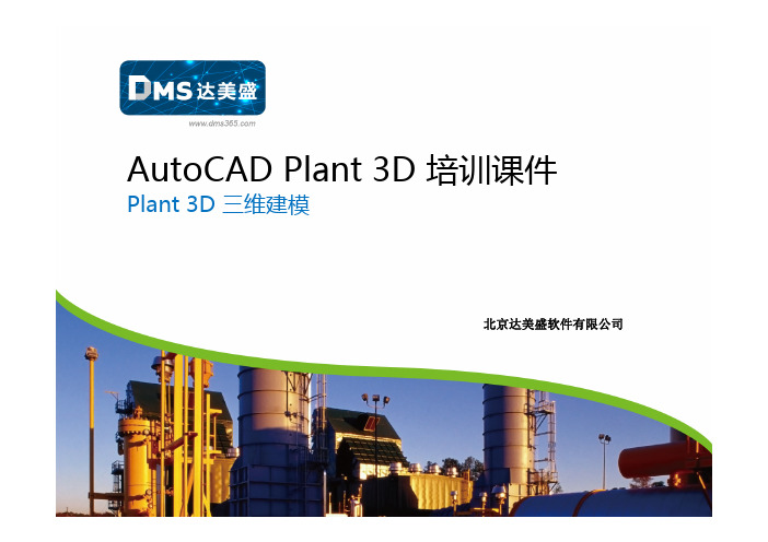
AutoCADPlant3D培训课件
Plant3D三维建模
北京达美盛软件有限公司
• 注意:要使用该功能,必须先安装 AutoCAD Plant3D,再安装 Navisworks。如果不能正常使用,可 在【控制面板】【卸载或更改程序】 中找到Autodesk Navisworks 2013 32bit or 64bit Exporter Plug-ins,重新 安装插件。
三维工厂建模基本流程 结构、建筑 模型
结构-杆件 5. 绘制横梁。点击【结构杆件】, 在命令行输入”S”,设置杆件方向 为顶部中心点。如下图所示:
6. 沿轴A1A3C3 C2 B2 B1 A1顶部走一圈。如右图所示: 7. 点击【结构剪切修剪杆件】, 以轴A3杆件为例,先选择用来修剪 的立柱,再选择被修剪的横梁。效 果如右图。不必终止命令,重复刚 才的操作,继续修剪其他交叉杆件。
12. 点击【建模拉伸】,选择矩形,向上拉伸300,生成屋顶。
- 1、下载文档前请自行甄别文档内容的完整性,平台不提供额外的编辑、内容补充、找答案等附加服务。
- 2、"仅部分预览"的文档,不可在线预览部分如存在完整性等问题,可反馈申请退款(可完整预览的文档不适用该条件!)。
- 3、如文档侵犯您的权益,请联系客服反馈,我们会尽快为您处理(人工客服工作时间:9:00-18:30)。
这些数据,导出成PCF的格式
和应力分析,或者管段预制等应用
程序进行完整的数据交互。
NavisWorks兼容性 三维的工厂模型和Navisworks是 快速的设计检视,渲染和碰撞检
直接相互兼容的。
查。
AutoDeks Inventor(设备三维设计)
4
三维工厂设计方案建议书
Autodesk Inventor 产品线是一系列用于三维机械设计、仿真、模具创建和设计交流 的软件,其功能全面,使用灵活,可以帮助用户经济高效地利用数字样机工作流在更 短时间内设计并创建更出色的产品。
连接性。你可以选择是半自动布管,
或者是完全手工式布管。
设备
完整的设备数据库,可以通过工具 更加简单的在工厂模型中创建,编
面板直接调用。您同样可以添加自 辑,管理和使用设备。
定义的设备到这个标准库中。
结构
参数化的创建一系列小型的结构组 快速识别工厂模型的干涉问题。非
件,包括AISC钢构件和子结构,例 常方便的就可以参考其他基于
AutoCAD Plant 3D 软件近年来在吸取各种软件的长处、优点的基础上,通过改进、优 化其设计理念,发展也十分迅速,其功能已逐步逼近工作站级三维工厂设计软件,在国际上 已被公认为权威的三维工厂设计软件之一。AutoCAD Plant 3D 系列工厂设计软件包括工艺 流程设计(P&ID),设备设计(Equipment)、 管道设计(Piping)、钢结构(structural)、电缆敷设 (Cable&Tray)、管线应力分析(Triflex)和管网流体分析(FluidFlow)等。
பைடு நூலகம்
如楼梯和直爬梯。
AutoCAD的三维结构软件
施工文档的生成
单管图,平立面图和其他施工文档 快速的生成和共享单管图,平立面
的生成
图和其他施工文档。所有的数据都
是三维模型直接交互的,有助于保
证施工文档数据的准确性,一致性,
和时效性。
报表,搜索和查询 在图纸里,直接搜索,查询和修改 快速生成和发布材料清册和报表。
件中。AutoCAD Plant 3D 模型可以和 Autodesk Navisworks 无缝集成,完成 设计检视,渲染和碰撞检查等工作。
功能
作用
优势
工作空间和用户界面 大型的画图窗口和直观的工具面 简单,方便的使用各种工具和命
板,提供了现代化的友好的用户界 令。快速找到非常用的工具,以及
AutoCAD Plant 3D(三维工厂设计)
AutoCAD Plant 3D 2011 是最佳的工厂设计,建模和施工图软件。依靠自生强大的 AutoCAD 平台,AutoCAD Plant 3D 给工厂的工程师和设计师带来了最现代化的 三维设计工具。类 似与等级驱动和完 整的元件库等功能, 使得管道,设备和 支撑结构定位非常 的方便。和 AutoCAD P&ID 完 整的数据交互功能, 使得单管图和平立 面图的生成更加有 效率,更加的准确。 加强设计和工
程效率 AutoCAD Plant 3D 是基于最新,最开放的 AutoCAD 平台上,培训和项目启 动的时间都很短。并不需要昂贵的服务器和数据库系统。AutoCAD Plant 3D 的等级驱动技术和现代化的界面,使得建模和管道,设备,结构支架的编辑, 以及其他工厂管件更加简单,易用。 保证数据的准确性和一致性 在 AutoCAD Plant 3D 里,三维模型,工艺流程图,单管图和平立面图之间的
2
三维工厂设计方案建议书
您可以在 AutoCAD P&ID 中自定义这些报表或新建自己的报表。 导入/导出到 Microsoft Excel 和 .csv 格式
P&ID 图纸中需要包含很多跨专业的信息。您可以通过导出图纸或项目的数据到 Microsoft Excel 或者 .CSV 格式的方式来与其它专业共享数据,然后将更新后 的信息导回到图纸中。您也可以将 P&ID 图纸转成包含数据的电子文档,而不 需要再从数据库中查询和过滤数据。 检查并审核数据的修改 当数据从 Excel 文件导入时,AutoCAD P&ID 能够轻易地识别所作的任何修改。 在 Data Manager 中点击高亮的修改部分,程序会提示已修改并在图纸中缩放到 相应的对象上,以便于确定是否需要修改。您可以一个一个地或批量地接受或拒 绝修改。这个功能可以帮助用户管理由其它部门工程师做的外部修改,维护图纸 的一致性。 自动生成位号并确保唯一 当您在图纸中增加一个对象时,AutoCAD P&ID 可以保证项目中所有图纸中对 象位号的唯一性。这样就可以防止用户在相同项目中使用相同的位号。另外,所 有符号和图元相关的数据信息都可以随时输入。 使用电子表格界面来搜索和编辑数据 AutoCAD P&ID 提供了一个以电子表格界面来管理所有图纸数据的工具―― Data Manager。您可以使用 Data Manager 来排序、过滤或者在您的 P&ID 图纸 中搜索元件,并快速输入这些对象的数据信息。被 Data Manager 编辑的管线号、 元件数据和其它数据将实时地更新到 P&ID 图纸中。Data Manager 的缩放功能 可以实时打开数据所在的图纸并缩放对应的图形到当前窗口上。
3
三维工厂设计方案建议书
基础数据都是直接关联的,这样就保证了数据的一致性和精确性。 在图纸
中可以直接搜索和查询数据,然后非常容易的就可以检查和修改数据。 增强整个项目团队的合作性
材料清单和报表可以很容易的生成,直接共享给整个项目团队。便携式的
AutoCAD Plant 3D 的 DWG 文件可以被其他专业的工程师直接用 AutoCAD 打开。 这些数据可以直接输出到类似于应力分析,或者管段预制等其他软
采用计算机辅助设计时,管道可以是单线,也可以是双线表示,这由操作人员选用。根 据操作可由三维配管模型抽出二维平,立面图,管段图或打印三维配管图。
1.2 业务特点及问题分析
当前的趋势是大家使用的计算机制图软件都是 AutoCAD,AutoCAD 是一个通用的制图 软件,与人工制图相比,采用 AutoCAD 制图修改方便,图面质量高;相对于三维计算机辅 助设计来讲,投资少,见效块,便于推广。但他有明显的技术上的缺陷,不能对所设计的工 程进行碰撞检查,设计速度明显比三维设计慢,需用其他辅助软件才能进行配管材料的统计, 无法共享数据库。
保持数据交互。
性。
等级库和元件库
先进的等级驱动技术和完整的
管道,设备,支撑结构和其他管件
ANSI/ASME (B16)和DIN/ISO标准的 布置起来更加的方便和简单。
元件库满足了项目的需求。
管道
布置管线,或者编辑管线上的管道 最出色的新建和编辑管线功能。
和管件,以及管理整个管线系统的
2011
AutoCAD Plant 3D 三维工厂设计方案建议书
三维工厂设计方案建议书
1 行业背景
1.1 设计行业 IT 发展
近几十年来,计算机在工程设计中的应用有飞跃的发展,使得传统的手工二维设计模式 遇到了前所未有的挑战。随着计算机硬件技术的发展,工程设计用的计算机由大型机到工作 站,再由工作站发展到微机。同时计算机应用技术(软件)也在不断的发展,电子计算机辅 助工程设计的功能由单一功能发展到多功能,再由多功能发展到综合功能。计算机在工程设 计的早期只是用于单个设备的工艺计算或设备强度计算。而今天的计算机系统可以进行整个 装置工艺流程的全流程模拟计算;模拟装置的运行工况;进行装置生产的最佳化;用于操作 人员的培训等等。