有限元分析中英文对照资料
有限元分析法英文简介
The finite element analysisFinite element method, the solving area is regarded as made up of many small in the node connected unit (a domain), the model gives the fundamental equation of sharding (sub-domain) approximation solution, due to the unit (a domain) can be divided into various shapes and sizes of different size, so it can well adapt to the complex geometry, complex material properties and complicated boundary conditionsFinite element model: is it real system idealized mathematical abstractions. Is composed of some simple shapes of unit, unit connection through the node, and under a certain load.Finite element analysis: is the use of mathematical approximation method for real physical systems (geometry and loading conditions were simulated. And by using simple and interacting elements, namely unit, can use a limited number of unknown variables to approaching infinite unknown quantity of the real system.Linear elastic finite element method is a ideal elastic body as the research object, considering the deformation based on small deformation assumption of. In this kind of problem, the stress and strain of the material is linear relationship, meet the generalized hooke's law; Stress and strain is linear, linear elastic problem boils down to solving linear equations, so only need less computation time. If the efficient method of solving algebraic equations can also help reduce the duration of finite element analysis.Linear elastic finite element generally includes linear elastic statics analysis and linear elastic dynamics analysis from two aspects. The difference between the nonlinear problem and linear elastic problems:1) nonlinear equation is nonlinear, and iteratively solving of general;2) the nonlinear problem can't use superposition principle;3) nonlinear problem is not there is always solution, sometimeseven no solution. Finite element to solve the nonlinear problem can be divided into the following three categories:1) material nonlinear problems of stress and strain is nonlinear,but the stress and strain is very small, a linear relationship between strain and displacement at this time, this kind of problem belongs tothe material nonlinear problems. Due to theoretically also cannotprovide the constitutive relation can be accepted, so, general nonlinear relations between stress and strain of the material based on the test data, sometimes, to simulate the nonlinear material properties available mathematical model though these models always have their limitations. More important material nonlinear problems in engineering practice are: nonlinear elastic (including piecewise linear elastic, elastic-plasticand viscoplastic, creep, etc.2) geometric nonlinear geometric nonlinear problems are caused dueto the nonlinear relationship between displacement. When the object the displacement is larger, the strain and displacement relationship is nonlinear relationship. Research on this kind of problemIs assumes that the material of stress and strain is linear relationship. It consists of a large displacement problem of largestrain and large displacement little strain. Such as the structure ofthe elastic buckling problem belongs to the large displacement little strain, rubber parts forming process for large strain.3) nonlinear boundary problem in the processing, problems such as sealing, the impact of the role of contact and friction can not be ignored, belongs to the highly nonlinear contact boundary.At ordinary times some contact problems, such as gear, stamping forming, rolling, rubber shock absorber, interference fit assembly, etc., when a structure and another structure or external boundary contact usually want to consider nonlinear boundary conditions. The actual nonlinear may appear at the same time these two or three kinds of nonlinear problems.Finite element theoretical basisFinite element method is based on variational principle and the weighted residual method, and the basic solving thought is the computational domain is divided into a finite number of non-overlapping unit, within each cell, select some appropriate nodes as solving the interpolation function, the differential equation of the variables inthe rewritten by the variable or its derivative selected interpolation node value and the function of linear expression, with the aid of variational principle or weighted residual method, the discrete solution of differential equation. Using different forms of weight function and interpolation function, constitute different finite element methods. 1. The weighted residual method and the weighted residual method ofweighted residual method of weighted residual method: refers to the weighted function is zero using make allowance for approximate solution of the differential equation method is called the weighted residual method. Is a kind of directly from the solution of differential equation and boundary conditions, to seek the approximate solution of boundary value problems of mathematical methods. Weighted residual method is to solve the differential equation of the approximate solution of a kind of effective method.Hybrid method for the trial function selected is the most convenient, but under the condition of the same precision, the workload is the largest. For internal method and the boundary method basis function must be made in advance to meet certain conditions, the analysis of complex structures tend to have certain difficulty, but the trial function is established, the workload is small. No matter what method is used, when set up trial function should be paid attention to are the following:(1) trial function should be composed of a subset of the complete function set. Have been using the trial function has the power series and trigonometric series, spline functions, beisaier, chebyshev, Legendre polynomial, and so on.(2) the trial function should have until than to eliminate surplus weighted integral expression of the highest derivative low first order derivative continuity.(3) the trial function should be special solution with analytical solution of the problem or problems associated with it. If computing problems with symmetry, should make full use of it. Obviously, anyindependent complete set of functions can be used as weight function. According to the weight function of the different options for different weighted allowance calculation method, mainly include: collocation method, subdomain method, least square method, moment method andgalerkin method. The galerkin method has the highest accuracy.Principle of virtual work: balance equations and geometricequations of the equivalent integral form of "weak" virtual work principles include principle of virtual displacement and virtual stress principle, is the floorboard of the principle of virtual displacementand virtual stress theory. They can be considered with some control equation of equivalent integral "weak" form. Principle of virtual work: get form any balanced force system in any state of deformationcoordinate condition on the virtual work is equal to zero, namely the system of virtual work force and internal force ofthe sum of virtual work is equal to zero. The virtual displacement principle is the equilibrium equation and force boundary conditions of the equivalent integral form of "weak"; Virtual stress principle is geometric equation and displacement boundary condition of the equivalent integral form of "weak". Mechanical meaning of the virtual displacement principle: if the force system is balanced, they on the virtual displacement and virtual strain by the sum of the work is zero. On the other hand, if the force system in the virtual displacement (strain) and virtual and is equal to zero for the work, they must balance equation. Virtual displacement principle formulated the system of force balance, therefore, necessary and sufficient conditions. In general, the virtual displacement principle can not only suitable for linear elastic problems,and can be used in the nonlinear elastic and elastic-plastic nonlinear problem.Virtual mechanical meaning of stress principle: if the displacement is coordinated, the virtual stress and virtual boundary constraint counterforce in which they are the sum of the work is zero. On the other hand, if the virtual force system in which they are and is zero for the work, they must be meet the coordination. Virtual stress in principle, therefore, necessary and sufficient condition for the expression of displacement coordination. Virtual stress principle can be applied to different linear elastic and nonlinear elastic mechanics problem. But it must be pointed out that both principle of virtual displacement and virtual stress principle, rely on their geometric equation and equilibrium equation is based on the theory of small deformation, they cannot be directly applied to mechanical problems based on large deformation theory. 3,,,,, the minimum total potential energy method of minimum total potential energy method, the minimum strain energy method of minimum total potential energy method, the potential energy function in the object on the external load will cause deformation, the deformation force during the work done in the form of elastic energy stored in the object, is the strain energy.The convergence of the finite element method, the convergence of the finite element method refers to when the grid gradually encryption, the finite element solution sequence converges to the exact solution; Or when the cell size is fixed, the more freedom degree each unit, thefinite element solutions tend to be more precise solution. Convergence condition of the convergence condition of the finite element finite element convergence condition of the convergence condition of the finiteelement finite element includes the following four aspects: 1) within the unit, the displacement function must be continuous. Polynomial is single-valued continuous function, so choose polynomial as displacement function, to ensure continuity within the unit. 2) within the unit, the displacement function must include often strain. Total can be broken down into each unit of the state of strain does not depend on different locations within the cell strain and strain is decided by the point location of variables. When the size of the units is enough hours, unit of each point in the strain tend to be equal, unit deformation is uniform, so often strain becomes the main part of the strain. To reflect the state of strain unit, the unit must include the displacement functions often strain. 3) within the unit, the displacement function must include the rigid body displacement. Under normal circumstances, the cell for a bit of deformation displacement and displacement of rigid body displacement including two parts. Deformation displacement is associated with the changes in the object shape and volume, thus producing strain; The rigid body displacement changing the object position, don't change the shape and volume of the object, namely the rigid body displacement is not deformation displacement. Spatial displacement of an object includes three translational and three rotational displacement, a total of six rigid body displacements. Due to a unit involved in the other unit, other units do rigid body displacement deformation occurs willdrive unit, thus, to simulate real displacement of a unit, assume that the element displacement function must include the rigid body displacement. 4) the displacement function must be coordinated in public boundary of the adjacent cell. For general unit of coordination isrefers to the adjacent cell in public node have the same displacement,but also have the same displacement along the edge of the unit, that is to say, to ensure that the unit does not occur from cracking and invade the overlap each other. To do this requires the function on the common boundary can be determined by the public node function value only. For general unit and coordination to ensure the continuity of the displacement of adjacent cell boundaries. However, between the plate and shell of the adjacent cell, also requires a displacement of the first derivative continuous, only in this way, to guarantee the strain energy of the structure is bounded. On the whole, coordination refers to the public on the border between neighboring units satisfy the continuity conditions. The first three, also called completeness conditions, meet the conditions of complete unit is complete unit; Article 4 is coordination requirements, meet the coordination unit coordination unit; Otherwise known as the coordinating units. Completeness requirement is necessary for convergence, all four meet, constitutes a necessary and sufficient condition for convergence. In practical application, to make the selected displacement functions all meet the requirements of completeness and harmony, it is difficult in some cases can relax the requirement for coordination. It should be pointed out that, sometimes the coordination unit than its corresponding coordination unit, its reason lies in the nature of the approximate solution. Assumed displacement function is equivalent to put the unit under constraint conditions, the unit deformation subject to the constraints, this just some alternative structure compared to the real structure. But the approximate structure due to allow cell separation, overlap, become soft, the stiffness of the unit or formed (such as round degree between continuous plate unit in the unit, and corner is discontinuous, just to pin point) for the coordination unit, the error of these two effectshave the possibility of cancellation, so sometimes use the coordination unit will get very good results. In engineering practice, the coordination of yuan must pass to use "small pieces after test". Average units or nodes average processing method of stress stress average units or nodes average processing method of stress average units or nodes average processing method of stress of the unit average or node average treatment method is the simplest method is to take stress results adjacent cell or surrounding nodes, the average value of stress.1. Take an average of 2 adjacent unit stress. Take around nodes, the average value of stressThe basic steps of finite element method to solve the problemThe structural discretization structure discretization structure discretization structure discretization to discretization of the whole structure, will be divided into several units, through the node connected to each other between the units; 2. The stiffness matrix of each unit and each element stiffness matrix and the element stiffness matrix and the stiffness matrix of each unit (3) integrated global stiffness matrix integrated total stiffness matrix integrated overall stiffness matrix integrated total stiffness matrix and write out the general balance equations and write out the general balance equations and write out the general balance equations and write a general equation4. Introduction of supporting conditions, the displacement of each node5. Calculate the stress and strain in the unit to get the stress and strain of each cell and the cell of the stress and strain and the stress and strain of each cell.For the finite element method, the basic ideas and steps can be summarized as: (1) to establishintegral equation, according to the principle of variational allowance and the weight function or equation principle of orthogonalization, establishment and integral expression of differential equations is equivalent to the initial-boundary value problem, this is the starting point of the finite element method. Unit (2) the area subdivision, according to the solution of the shape of the area and the physical characteristics of practical problems, cut area is divided into a number of mutual connection, overlap of unit. Regional unit is divided into finite element method of the preparation, this part of the workload is bigger, in addition to the cell and node number and determine the relationship between each other, also said the node coordinates, at the same time also need to list the natural boundary and essential boundary node number and the corresponding boundary value.(3) determine the unit basis function, according to the unit and the approximate solution of node number in precision requirement, choose meet certain interpolation condition basis function interpolation function as a unit. Basis function in the finite element method is selected in the unit, due to the geometry of each unit has a rule in the selection of basis function can follow certain rules. (4) the unit will be analysis: to solve the function of each unit with unit basis functions to approximate the linear combination of expression; Then approximate function generation into the integral equation, and the unit area integral, can be obtained with undetermined coefficient (i.e., cell parameter value) of each node in the algebraic equations, known as the finite element equation.(5) the overall synthesis: after the finite element equation, the area of all elements in the finite element equation according to certain principles of accumulation, the formation of general finite element equations. (6) boundary condition processing: general boundaryconditions there are three kinds of form, divided into the essential boundary conditions (dirichlet boundary condition) and natural boundary conditions (Riemann boundary conditions) and mixed boundary conditions (cauchy boundary conditions). Often in the integral expression fornatural boundary conditions, can be automatically satisfied. Foressential boundary conditions and mixed boundary conditions, should bein a certain method to modify general finite element equations satisfies. Solving finite element equations (7) : based on the general finite element equations of boundary conditions are fixed, are all closed equations of the unknown quantity, and adopt appropriate numerical calculation method, the function value of each node can be obtained.。
车架有限元分析外文文献翻译

南京林业大学本科毕业设计(论文)外文资料翻译翻译资料名称(外文)Stress analysis of heavy duty truck chassis as apreliminary data for its fatigue life predictionusing FEM翻译资料名称(中文)利用重型载货汽车的有限元应力分析的初步数据预测其疲劳寿命院(系):汽车与交通工程学院专业:机械制造及其自动化(汽车设计方向)姓名:学号:指导教师:完成日期: 2012/5/31利用重型载货汽车的有限元应力分析的初步数据预测其疲劳寿命Roslan Abd Rahman, Mohd Nasir Tamin, Ojo Kurdi马来西亚工程大学机械工程系81310 UTM, Skudai,Johor Bahru摘要本文对一重型货车底盘做了应力分析。
应力分析能够确定零件的最大受力点,是分析零部件疲劳研究和寿命预测的重要手段。
前人已有用商用有限元软件ABAQUS软件对底盘模型进行分析的。
本次研究的底盘长12.35米,宽2.45米,材料是ASTM低合金钢710(3级),屈服极限552MPa,抗拉强度620MPa。
分析结果显示,最大应力点出现在底盘与螺栓连接的空缺处,最大应力为386.9MPa,底盘的疲劳破坏将会从最大应力点开始向车架各部位蔓延。
关键字:应力分析,疲劳寿命预测,货车底盘1.0简介在马来西亚,很多货车的车架寿命都有20多年,20多年架就会有使用安全的问题。
因此,为了确保底盘在工作期间的安全性能,就有必要对底盘作疲劳研究和寿命预测。
利用有限元法作应力分析能够确定受最大应力的关键点,这个关键点是导致底盘疲劳损伤的因素之一。
应力的大小能够预测底盘的寿命,所以可以根据应力分析的结果精确地预测底盘的寿命,应力分析越精确,底盘寿命预测的越合理。
本文是用商用有限元软件ABAQUS 软件完成底盘应力分析的。
汽车工业(汽车总成及各部件)在马来西亚的工业中占据非常重要的地位。
有限元分析中英文对照资料知识讲解

有限元分析中英文对照资料The finite element analysisFinite element method, the solving area is regarded as made up of many small in the node connected unit (a domain), the model gives the fundamental equation of sharding (sub-domain) approximation solution, due to the unit (a domain) can be divided into various shapes and sizes of different size, so it can well adapt to the complex geometry, complex material properties and complicated boundary conditions Finite element model: is it real system idealized mathematical abstractions. Is composed of some simple shapes of unit, unit connection through the node, and under a certain load.Finite element analysis: is the use of mathematical approximation method for real physical systems (geometry and loading conditions were simulated. And by using simple and interacting elements, namely unit, can use a limited number of unknown variables to approaching infinite unknown quantity of the real system.Linear elastic finite element method is a ideal elastic body as the research object, considering the deformation based on small deformation assumption of. In this kindof problem, the stress and strain of the material is linear relationship, meet the generalized hooke's law; Stress and strain is linear, linear elastic problem boils down to solving linear equations, so only need less computation time. If the efficient method of solving algebraic equations can also help reduce the duration of finite element analysis.Linear elastic finite element generally includes linear elastic statics analysis and linear elastic dynamics analysis from two aspects. The difference between the nonlinear problem and linear elastic problems:1) nonlinear equation is nonlinear, and iteratively solving of general;2) the nonlinear problem can't use superposition principle;3) nonlinear problem is not there is always solution, sometimes even no solution. Finite element to solve the nonlinear problem can be divided into the following three categories:1) material nonlinear problems of stress and strain is nonlinear, but the stress and strain is very small, a linear relationship between strain and displacement at this time, this kind of problem belongs to the material nonlinear problems. Due to theoretically also cannot provide the constitutive relation can be accepted, so, general nonlinear relations between stress and strain of the material based on the test data, sometimes, to simulate the nonlinear material properties available mathematical model though these models always have their limitations. More important material nonlinear problems in engineering practice are: nonlinear elastic (including piecewise linear elastic, elastic-plastic and viscoplastic, creep, etc.2) geometric nonlinear geometric nonlinear problems are caused due to the nonlinear relationship between displacement. When the object the displacement is larger, the strain and displacement relationship is nonlinear relationship. Research on this kind of problemIs assumes that the material of stress and strain is linear relationship. It consists of a large displacement problem of large strain and large displacement little strain. Such as the structure of the elastic buckling problem belongs to the large displacement little strain, rubber parts forming process for large strain.3) nonlinear boundary problem in the processing, problems such as sealing, the impact of the role of contact and friction can not be ignored, belongs to the highly nonlinear contact boundary. At ordinary times some contact problems, such as gear, stamping forming, rolling, rubber shock absorber, interference fit assembly, etc., when a structure and another structure or external boundary contact usually want to consider nonlinear boundary conditions. The actual nonlinear may appear at the same time these two or three kinds of nonlinear problems.Finite element theoretical basisFinite element method is based on variational principle and the weighted residual method, and the basic solving thought is the computational domain is divided into a finite number of non-overlapping unit, within each cell, select some appropriate nodes as solving the interpolation function, the differential equation of the variables in the rewritten by the variable or its derivative selected interpolation node value and the function of linear expression, with the aid of variational principle or weighted residual method, the discrete solution of differential equation. Using different forms of weight function and interpolation function, constitute different finite element methods. 1. The weighted residual method and the weighted residual method of weighted residual method of weighted residual method: refers to the weighted function is zero using make allowance for approximate solution of the differential equation method is called the weighted residual method. Is a kind of directly from the solution of differential equation and boundary conditions, to seek the approximate solution of boundary value problems of mathematical methods. Weighted residual method is to solve the differential equation of the approximate solution of a kind of effective method. Hybrid method for the trial function selected is the most convenient, but under the condition of the same precision, the workload is the largest. For internal method and the boundary method basis function must be made in advance to meet certain conditions, the analysis of complex structures tend to have certain difficulty, but the trial function is established, the workload is small. No matter what method is used, when set up trial function should be paid attention to are the following:(1) trial function should be composed of a subset of the complete function set. Have been using the trial function has the power series and trigonometric series, spline functions, beisaier, chebyshev, Legendre polynomial, and so on.(2) the trial function should have until than to eliminate surplus weighted integral expression of the highest derivative low first order derivative continuity.(3) the trial function should be special solution with analytical solution of the problem or problems associated with it. If computing problems with symmetry, should make full use of it. Obviously, any independent complete set of functions can be used as weight function. According to the weight function of the different options fordifferent weighted allowance calculation method, mainly include: collocation method, subdomain method, least square method, moment method and galerkin method. The galerkin method has the highest accuracy.Principle of virtual work: balance equations and geometric equations of the equivalent integral form of "weak" virtual work principles include principle of virtual displacement and virtual stress principle, is the floorboard of the principle of virtual displacement and virtual stress theory. They can be considered with some control equation of equivalent integral "weak" form. Principle of virtual work: get form any balanced force system in any state of deformation coordinate condition on the virtual work is equal to zero, namely the system of virtual work force and internal force of the sum of virtual work is equal to zero. The virtual displacement principle is the equilibrium equation and force boundary conditions of the equivalent integral form of "weak"; Virtual stress principle is geometric equation and displacement boundary condition of the equivalent integral form of "weak". Mechanical meaning of the virtual displacement principle: if the force system is balanced, they on the virtual displacement and virtual strain by the sum of the work is zero. On the other hand, if the force system in the virtual displacement (strain) and virtual and is equal to zero for the work, they must balance equation. Virtual displacement principle formulated the system of force balance, therefore, necessary and sufficient conditions. In general, the virtual displacement principle can not only suitable for linear elastic problems, and can be used in the nonlinear elastic and elastic-plastic nonlinear problem.Virtual mechanical meaning of stress principle: if the displacement is coordinated, the virtual stress and virtual boundary constraint counterforce in which they are the sumof the work is zero. On the other hand, if the virtual force system in which they are and is zero for the work, they must be meet the coordination. Virtual stress in principle, therefore, necessary and sufficient condition for the expression of displacement coordination. Virtual stress principle can be applied to different linear elastic and nonlinear elastic mechanics problem. But it must be pointed out that both principle of virtual displacement and virtual stress principle, rely on their geometric equation and equilibrium equation is based on the theory of small deformation, they cannot be directly applied to mechanical problems based on large deformation theory. 3,,,,, the minimum total potential energy method of minimum total potential energy method, the minimum strain energy method of minimum total potential energy method, the potential energy function in the object on the external load will cause deformation, the deformation force during the work done in the form of elastic energy stored in the object, is the strain energy.The convergence of the finite element method, the convergence of the finite element method refers to when the grid gradually encryption, the finite element solution sequence converges to the exact solution; Or when the cell size is fixed, the more freedom degree each unit, the finite element solutions tend to be more precise solution. Convergence condition of the convergence condition of the finite element finite element convergence condition of the convergence condition of the finite element finite element includes the following four aspects: 1) within the unit, the displacement function must be continuous. Polynomial is single-valued continuous function, sochoose polynomial as displacement function, to ensure continuity within the unit. 2) within the unit, the displacement function must include often strain. Total can be broken down into each unit of the state of strain does not depend on different locations within the cell strain and strain is decided by the point location of variables. When the size of the units is enough hours, unit of each point in the strain tend to be equal, unit deformation is uniform, so often strain becomes the main part of the strain. To reflect the state of strain unit, the unit must include the displacement functions often strain. 3) within the unit, the displacement function must include the rigid body displacement. Under normal circumstances, the cell for a bit of deformation displacement and displacement of rigid body displacement including two parts. Deformation displacement is associated with the changes in the object shape and volume, thus producing strain; The rigid body displacement changing the object position, don't change the shape and volume of the object, namely the rigid body displacement is not deformation displacement. Spatial displacement of an object includes three translational and three rotational displacement, a total of six rigid body displacements. Due to a unit involved in the other unit, other units do rigid body displacement deformation occurs will drive unit, thus, to simulate real displacement of a unit, assume that the element displacement function must include the rigid body displacement. 4) the displacement function must be coordinated in public boundary of the adjacent cell. For general unit of coordination is refers to the adjacent cell in public node have the same displacement, but also have the same displacement along the edge of the unit, that is to say, to ensure that the unit does not occur from cracking and invade the overlap each other. To do this requires the function on the common boundary can be determined by the public node function value only. For general unit and coordination to ensure the continuity of the displacement of adjacent cell boundaries. However, between the plate and shell of the adjacent cell, also requires a displacement of the first derivative continuous, only in this way, to guarantee the strain energy of the structure is bounded. On the whole, coordination refers to the public on the border between neighboring units satisfy the continuity conditions. The first three, also called completeness conditions, meet the conditions of complete unit is complete unit; Article 4 is coordination requirements, meet the coordination unit coordination unit; Otherwise known as the coordinating units. Completeness requirement is necessary for convergence, all four meet, constitutes a necessary and sufficient condition for convergence. In practical application, to make the selected displacement functions all meet the requirements of completeness and harmony, it is difficult in some cases can relax the requirement for coordination. It should be pointed out that, sometimes the coordination unit than its corresponding coordination unit, its reason lies in the nature of the approximate solution. Assumed displacement function is equivalent to put the unit under constraint conditions, the unit deformation subject to the constraints, this just some alternative structure compared to the real structure. But the approximate structure due to allow cell separation, overlap, become soft, the stiffness of the unit or formed (such as round degree between continuous plate unit in the unit, and corner is discontinuous, just to pin point) for the coordination unit, the error of these two effects have the possibility of cancellation, so sometimes use thecoordination unit will get very good results. In engineering practice, the coordination of yuan must pass to use "small pieces after test". Average units or nodes average processing method of stress stress average units or nodes average processing method of stress average units or nodes average processing method of stress of the unit average or node average treatment method is the simplest method is to take stress results adjacent cell or surrounding nodes, the average value of stress.1. Take an average of 2 adjacent unit stress. Take around nodes, the average value of stressThe basic steps of finite element method to solve the problemThe structural discretization structure discretization structure discretization structure discretization to discretization of the whole structure, will be divided into several units, through the node connected to each other between the units; 2. The stiffness matrix of each unit and each element stiffness matrix and the element stiffness matrix and the stiffness matrix of each unit (3) integrated global stiffness matrix integrated total stiffness matrix integrated overall stiffness matrix integrated total stiffness matrix and write out the general balance equations and write out the general balance equations and write out the general balance equations and write a general equation 4. Introduction of supporting conditions, the displacement of each node 5. Calculate the stress and strain in the unit to get the stress and strain of each cell and the cell of the stress and strain and the stress and strain of each cell.For the finite element method, the basic ideas and steps can be summarized as: (1) to establish integral equation, according to the principle of variational allowance and the weight function or equation principle of orthogonalization, establishment and integral expression of differential equations is equivalent to the initial-boundary value problem, this is the starting point of the finite element method. Unit (2) the area subdivision, according to the solution of the shape of the area and the physical characteristics of practical problems, cut area is divided into a number of mutual connection, overlap of unit. Regional unit is divided into finite element method of the preparation, this part of the workload is bigger, in addition to the cell and node number and determine the relationship between each other, also said the node coordinates, at the same time also need to list the natural boundary and essential boundary node number and the corresponding boundary value. (3) determine the unit basis function, according to the unit and the approximate solution of node number in precision requirement, choose meet certain interpolation condition basis function interpolation function as a unit. Basis function in the finite element method is selected in the unit, due to the geometry of each unit has a rule in the selection of basis function can follow certain rules. (4) the unit will be analysis: to solve the function of each unit with unit basis functions to approximate the linear combination of expression; Then approximate function generation into the integral equation, and the unit area integral, can be obtained with undetermined coefficient (i.e., cell parameter value) of each node in the algebraic equations, known as the finite element equation.(5) the overall synthesis: after the finite element equation, the area of all elements inthe finite element equation according to certain principles of accumulation, the formation of general finite element equations. (6) boundary condition processing: general boundary conditions there are three kinds of form, divided into the essential boundary conditions (dirichlet boundary condition) and natural boundary conditions (Riemann boundary conditions) and mixed boundary conditions (cauchy boundary conditions). Often in the integral expression for natural boundary conditions, can be automatically satisfied. For essential boundary conditions and mixed boundary conditions, should be in a certain method to modify general finite element equations satisfies. Solving finite element equations (7) : based on the general finite element equations of boundary conditions are fixed, are all closed equations of the unknown quantity, and adopt appropriate numerical calculation method, the function value of each node can be obtained.有限元分析有限元法求解区域是由许多小的节点连接单元(域),该模型给出了切分的基本方程(子域名)的近似解,由于单位(域)可以分为不同的形状和大小不同的尺寸,所以它能很好的适应复杂的几何形状、材料特性和边界条件复杂,复杂有限元模型:它是真实系统的理想化的数学抽象。
有限元应用的参考译文
有限元应用参考译文Finite Element AnalysisFinite Element Analysis (FEA), also known as the Finite Element Method (FEM), is probably the most important tool added to the mechanical design engineer's toolkit this century. The development of FEA has been driven by the desire for more accurate design computations in more complex situations, allowing improvements in both the design procedure and products. The growing use of FEA has been made possible by the creation of computation engines that are capable of handling the immense volume of calculations necessary to prepare and carry out an analysis and easily display the results for interpretation. With the advent of very powerful desktop workstations, FEA is now available at a practical cost to virtually all engineers and designers.有限元分析(FEA),也称为有限元法(FEM),可能是本世纪提供给机械设计工程师使用的最重要的设计工具之一。
有限元分析报告报告材料英文文献
有限元分析报告报告材料英文文献The Basics of FEA Procedure有限元分析程序的基本知识2.1 IntroductionThis chapter discusses the spring element, especially for the purpose of introducing various concepts involved in use of the FEA technique.本章讨论了弹簧元件,特别是用于引入使用的有限元分析技术的各种概念的目的A spring element is not very useful in the analysis of real engineering structures; however, it represents a structure in an ideal form for an FEA analysis. Spring element doesn’t require discretization (division into smaller elements) and follows the basic equation F = ku.在分析实际工程结构时弹簧元件不是很有用的;然而,它代表了一个有限元分析结构在一个理想的形式分析。
弹簧元件不需要离散化(分裂成更小的元素)只遵循的基本方程F = ku We will use it solely for the purpose of developing an understanding of FEA concepts and procedure.我们将使用它的目的仅仅是为了对开发有限元分析的概念和过程的理解。
2.2 Overview概述Finite Element Analysis (FEA), also known as finite element method (FEM) is based on the concept that a structure can be simulated by the mechanicalbehavior of a spring in which the applied force is proportional to the displacement of the spring and the relationship F = ku is satisfied.有限元分析(FEA),也称为有限元法(FEM),是基于一个结构可以由一个弹簧的力学行为模拟的应用力弹簧的位移成正比,F = ku切合的关系。
塔式起重机有限元分析外文翻译
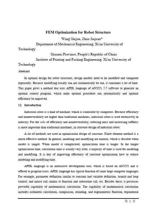
FEM Optimization for Robot StructureWang Shijun, Zhao Jinjuan*Department of Mechanical Engineering, Xi'an University of TechnologyShaanxi Province, People's Republic of ChinaInstitute of Printing and Packing Engineering, Xi'an University of TechnologyAbstractIn optimal design for robot structures, design models need to he modified and computed repeatedly. Because modifying usually can not automatically be run, it consumes a lot of time. This paper gives a method that uses APDL language of ANSYS 5.5 software to generate an optimal control program, which mike optimal procedure run automatically and optimal efficiency be improved.1)IntroductionIndustrial robot is a kind of machine, which is controlled by computers. Because efficiency and maneuverability are higher than traditional machines, industrial robot is used extensively in industry. For the sake of efficiency and maneuverability, reducing mass and increasing stiffness is more important than traditional machines, in structure design of industrial robot.A lot of methods are used in optimization design of structure. Finite element method is a much effective method. In general, modeling and modifying are manual, which is feasible when model is simple. When model is complicated, optimization time is longer. In the longer optimization time, calculation time is usually very little, a majority of time is used for modeling and modifying. It is key of improving efficiency of structure optimization how to reduce modeling and modifying time.APDL language is an interactive development tool, which is based on ANSYS and is offered to program users. APDL language has typical function of some large computer languages. For example, parameter definition similar to constant and variable definition, branch and loop control, and macro call similar to function and subroutine call, etc. Besides these, it possesses powerful capability of mathematical calculation. The capability of mathematical calculation includes arithmetic calculation, comparison, rounding, and trigonometric function, exponentialfunction and hyperbola function of standard FORTRAN language, etc. By means of APDL language, the data can be read and then calculated, which is in database of ANSYS program, and running process of ANSYS program can be controlled.Fig. 1 shows the main framework of a parallel robot with three bars. When the length of three bars are changed, conjunct end of three bars can follow a given track, where robot hand is installed. Core of top beam is triangle, owing to three bars used in the design, which is showed in Fig.2. Use of three bars makes top beam nonsymmetrical along the plane that is defined by two columns. According to a qualitative analysis from Fig.1, Stiffness values along z-axis are different at three joint locations on the top beam and stiffness at the location between bar 1 and top beam is lowest, which is confirmed by computing results of finite element, too. According to design goal, stiffness difference at three joint locations must he within a given tolerance. In consistent of stiffness will have influence on the motion accuracy of the manipulator under high load, so it is necessary to find the accurate location of top beam along x-axis.To the questions presented above, the general solution is to change the location of the top beam many times, compare the results and eventually find a proper position, The model will be modified according to the last calculating result each time. It is difficult to avoid mistakes if the iterative process is controlled manually and the iterative time is too long. The outer wall and inner rib shapes of the top beam will be changed after the model is modified. To find the appropriate location of top beam, the model needs to be modified repetitiously.Fig. 1 Solution of Original DesignThis paper gives an optimization solution to the position optimization question of the top beam by APDL language of ANSYS program. After the analysis model first founded, the optimization control program can be formed by means of modeling instruction in the log file. The later iterative optimization process can be finished by the optimization control program and do not need manual control. The time spent in modifying the model can be decreased to the ignorable extent. The efficiency of the optimization process is greatly improved.2)Construction of model for analysisThe structure shown in Fig. 1 consists of three parts: two columns, one beam and threedriving bars. The columns and beam are joined by the bolts on the first horizontal rib located on top of the columns as shown in Fig.1. Because the driving bars are substituted by equivalent forces on the joint positions, their structure is ignored in the model.The core of the top beam is three joints and a hole with special purpose, which can not be changed. The other parts of the beam may be changed if needed. For the convenience of modeling, the core of the beam is formed into one component. In the process of optimization, only the core position of beam along x axis is changed, that is to say, shape of beam core is not changed. It should be noticed that, in the rest of beam, only shape is changed but the topology is not changed and which can automatically be performed by the control program.Fig.1, six bolts join the beam and two columns. The joint surface can not bear the pull stress in the non-bolt joint positions, in which it is better to set contact elements. When the model includes contact elements, nonlinear iterative calculation will be needed in the process of solution and the computing time will quickly increase. The trial computing result not including contact element shows that the outside of beam bears pulling stress and the inner of beam bears the press stress. Considering the primary analysis object is the joint position stiffness between the top beam and the three driving bars, contact elements may not used, hut constructs the geometry model of joint surface as Fig.2 showing. The upper surface and the undersurface share one key point in bolt-joint positions and the upper surface and the under surface separately possess own key points in no bolt positions. When meshed, one node will be created at shared key point, where columns and beam are joined, and two nodes will be created at non shared key point, where column and beam are separated. On right surface of left column and left surface of right column, according to trial computing result, the structure bears press stress. Therefore, the columns and beam will share all key points, not but at bolts. This can not only omit contact element but also show the characteristic of bolt joining. The joining between the bottoms of the columns and the base are treated as full constraint. Because the main aim of analysis is the stiffness of the top beam, it can be assumed that the joint positions hear the same as load between beam and the three driving bars. The structure is the thin wall cast and simulated by shell element . The thickness of the outside wall of the structure and the rib are not equal, so twogroups of real constant should he set. For the convenience of modeling, the two columns are also set into another component. The components can create an assembly. In this way, the joint positions between the beam core and columns could he easily selected, in the modifying the model and modifying process can automatically be performed. Analysis model is showed Fig.1. Because model and load are symmetric, computing model is only half. So the total of elements is decreased to 8927 and the total of nodes is decreased to 4341. All elements are triangle.3.)Optimization solutionThe optimization process is essentially a computing and modifying process. The original design is used as initial condition of the iterative process. The ending condition of the process is that stiffness differences of the joint locations between three driving bars and top beam are less than given tolerance or iterative times exceed expected value. Considering the speciality of the question, it is foreseen that the location is existent where stiffness values are equal. If iterative is not convergent, the cause cannot be otherwise than inappropriate displacement increment or deficient iterative times. In order to make the iterative process convergent quickly and efficiently, this paper uses the bisection searching method changing step length to modify the top beam displacement. This method is a little complex but the requirement on the initial condition is relatively mild.The flow chart of optimization as follows:1. Read the beam model data in initial position from backup file;2. Modify the position of beam;3. Solve;4. Read the deform of nodes where beam and three bars are joined;5. Check whether the convergent conditions are satisfied, if not, then continue to modify the beam displacement and return to 3, otherwise, exit the iteration procedure.6. Save the results and then exit.The program's primary control codes and their function commentaries are given in it, of which the detailed modeling instructions are omitted. For the convenience of comparing with the control flow, the necessary notes are added.the flag of the batch file in ANSYSBATCH RESUME, robbak.db, 0read original data from the backupfile robbak,.db/PREP7 enter preprocessordelete the joint part between beam core and columnsmove the core of the beam by one :step lengthapply load and constraint on the geometry meshing thejoint position between beam core and columns FINISH exit the preprocessorISOLU enter solverSOLVE solveFINISH exit the solverPOST1 enter the postprocessor*GET ,front,NODE,2013,U,Z read the deformation of first joint node on beam*GET,back,NODE, 1441 ,U,Z read the deformation of second joint node on beam intoparameter hacklastdif-1 the absolute of initial difference between front and hacklast timeflag=- 1 the feasibility flag of the optimizationstep=0.05 the initial displacement from initial position to the currentposition*D0,1,1,10,1 the iteration procedure begin, the cycle variable is I andits value range is 1-10 and step length is 1dif=abs(front-back) the absolute of the difference between front and hack inthe current result*IF,dif,LE,l .OE-6,THEN check whether the absolute difference dif satisfies therequest or noflag=l yes, set flag equal to 1*EXIT exit the iterative calculation*ELSEIF,dif,GE,lastdif,THEN check whether the dif value becomes great or not flag=2yes, set flag 2 modify step length by bisection methodperform the next iterative calculation, use the lastposition as the current position and modified last steplength as the current step lengthELSE if the absolute of difference value is not less thanexpected value and become small gradually, continue tomove top beam read the initial condition from back upfile enter the preprocessorMEN, ,P51X, , , step,, , ,1 move the core of the beam by one step length modify thejoint positions between beam core and column applyload and constraint meshingFINISH exit preprocessorISOLU enter solverSOLVE solveFINISH exit the solver/POST1 exit the postprocessor*GET,front,NODE,201 3,U,Z read the deformation of first joint node to parameter front *GET,back,NODE, 144 1,U,Z read the deformation of second joint node to parameter back lastdif-dif update the value of last dif*ENDIF the end of the if-else*ENDDO the end of the DO cycleMost of the control program above is copied from log file, which is long. The total of lines is up to about 1000 lines. Many codes such as modeling and post-process codes are used repeatedly. To make the program construct clear, these instructions can he made into macros, which are called by main program. This can efficiently reduce the length of the main program. In addition, modeling instructions from log file includes lots of special instructions that are only used under graphic mode but useless under hatch mode. Deleting and modifying these instructions when under batch mode in ANSYS can reduce the length of the file, too.In the program above, the deformation at given position is read from node deformation. In meshing, in order to avoid generating had elements, triangle mesh is used. In optimization, the shape of joint position between columns and beam continually is changed. This makes total of elements different after meshing each time and then element numbering different, too. Data read from database according to node numbering might not he data to want. Therefore, beam core first needs to he meshed, then saved. When read next time, its numbering is the same as last time.Evaluating whether the final result is a feasible result or not needs to check the flag value. Ifonly the flag value is I, the result is feasible, otherwise the most proper position is not found. The total displacement of top beam is saved in parameter step. If the result is feasible, the step value is the distance from initial position to the most proper position. The sum of iterative is saved in parameter 1. According to the final value of I, feasibility of analysis result and correctness of initial condition can he evaluated.4)Optimization resultsThe sum of iterative in optimization is seven, and it takes about 2 hour and 37 minutes to find optimal position. Fig.3 shows the deformation contour of the half-construct. In Fig.3, the deformations in three joints between beam and the three driving bars is the same as level, and the corresponding deformation range is between -0.133E-04 and -0.1 15E-O4m, the requirement of the same stiffness is reached. At this time, the position of beam core along x-axis as shown in Fig. 1 has moved -0.71E-01m compared with the original designed positionBecause the speed of computer reading instruction is much faster than modifying model manually, the time modifying model can be ignored. The time necessary foroptimization mostly depends on the time of solution. Compared with the optimization procedure manually modifying model, the efficiency is improved and mistake operating in modeling is avoided.5)ConclusionThe analyzing result reveals that the optimization method given in this paper is effective and reaches the expected goal. The first advantage of this method is that manual mistakes do not easily occur in optimization procedure. Secondly, it is pretty universal and the control codes given in this paper may he transplanted to use in similar structure optimization design without large modification. The disadvantage is that the topology structure of the optimization object can not be changed. The more the workload of modifying the model, the more the advantages of this method are shown. In addition, the topology optimization function provided in ANSYS is used to solve the optimization problem that needs to change the topology structure.The better optimization results can he achieved if the method in this paper combined with中文译文:机器人机构优化设计有限元分析王世军赵金娟西安大学机电工程系中国陕西西安大学出版社摘要机器人结构最优化设计,设计模型需要反复的修正和计算。
有限元分析报告报告材料法英文简介
The finite element analysisFinite element method, the solving area is regarded as made up of many small in the node connected unit (a domain), the model gives the fundamental equation of sharding (sub-domain) approximation solution, due to the unit (a domain) can be divided into various shapes and sizes of different size, so it can well adapt to the complex geometry, complex material properties and complicated boundary conditionsFinite element model: is it real system idealized mathematical abstractions. Is composed of some simple shapes of unit, unit connection through the node, and under a certain load.Finite element analysis: is the use of mathematical approximation method for real physical systems (geometry and loading conditions were simulated. And by using simple and interacting elements, namely unit, can use a limited number of unknown variables to approaching infinite unknown quantity of the real system. Linear elastic finite element method is a ideal elastic body as the research object, considering the deformation based on small deformation assumption of. In this kind of problem, the stress and strain of the material is linear relationship, meet the generalized hooke's law; Stress and strain is linear, linear elastic problem boils down to solving linear equations, so only need less computation time. If the efficient method of solving algebraic equations can also help reduce the duration of finiteelement analysis.Linear elastic finite element generally includes linear elastic statics analysis and linear elastic dynamics analysis from two aspects. The difference between the nonlinear problem and linear elastic problems:1) nonlinear equation is nonlinear, and iteratively solving of general;2) the nonlinear problem can't use superposition principle;3) nonlinear problem is not there is always solution, sometimes even no solution. Finite element to solve the nonlinear problem can be divided into the following three categories:1) material nonlinear problems of stress and strain is nonlinear, but the stress and strain is very small, a linear relationship between strain and displacement at this time, this kind of problem belongs to the material nonlinear problems. Due to theoretically also cannot provide the constitutive relation can be accepted, so, general nonlinear relations between stress and strain of the material based on the test data, sometimes, to simulate the nonlinear material properties available mathematical model though these models always have their limitations. More important material nonlinear problems in engineering practice are: nonlinear elastic (including piecewise linear elastic, elastic-plastic and viscoplastic, creep, etc.2) geometric nonlinear geometric nonlinear problems are caused due to the nonlinear relationship between displacement. When the object the displacement is larger, the strain and displacement relationship is nonlinear relationship. Research on this kind of problemIs assumes that the material of stress and strain is linear relationship. It consists of a large displacement problem of large strain and large displacement little strain. Such as the structure of the elastic buckling problem belongs to the large displacement little strain, rubber parts forming process for large strain.3) nonlinear boundary problem in the processing, problems such as sealing, the impact of the role of contact and friction can not be ignored, belongs to the highly nonlinear contact boundary. At ordinary times some contact problems, such as gear, stamping forming, rolling, rubber shock absorber, interference fit assembly, etc., when a structure and another structure or external boundary contact usually want to consider nonlinear boundary conditions. The actual nonlinear may appear at the same time these two or three kinds of nonlinear problems.Finite element theoretical basisFinite element method is based on variational principle and the weighted residual method, and the basic solving thought is the computational domain is divided into a finite number of non-overlapping unit, within each cell, select some appropriate nodes as solving the interpolation function, the differential equation of the variables in the rewritten by the variable or its derivative selected interpolation node value and the function of linear expression, with the aid of variational principle or weighted residual method, the discrete solution of differential equation. Using different forms of weight function and interpolation function, constitutedifferent finite element methods. 1. The weighted residual method and the weighted residual method of weighted residual method of weighted residual method: refers to the weighted function is zero using make allowance for approximate solution of the differential equation method is called the weighted residual method. Is a kind of directly from the solution of differential equation and boundary conditions, to seek the approximate solution of boundary value problems of mathematical methods. Weighted residual method is to solve the differential equation of the approximate solution of a kind of effective method. Hybrid method for the trial function selected is the most convenient, but under the condition of the same precision, the workload is the largest. For internal method and the boundary method basis function must be made in advance to meet certain conditions, the analysis of complex structures tend to have certain difficulty, but the trial function is established, the workload is small. No matter what method is used, when set up trial function should be paid attention to are the following:(1) trial function should be composed of a subset of the complete function set. Have been using the trial function has the power series and trigonometric series, spline functions, beisaier, chebyshev, Legendre polynomial, and so on.(2) the trial function should have until than to eliminate surplus weighted integral expression of the highest derivative low first order derivative continuity.(3) the trial function should be special solution with analytical solution of the problem or problems associated with it. If computing problems with symmetry, should make full use of it. Obviously, any independent complete set of functionscan be used as weight function. According to the weight function of the different options for different weighted allowance calculation method, mainly include: collocation method, subdomain method, least square method, moment method and galerkin method. The galerkin method has the highest accuracy.Principle of virtual work: balance equations and geometric equations of the equivalent integral form of "weak" virtual work principles include principle of virtual displacement and virtual stress principle, is the floorboard of the principle of virtual displacement and virtual stress theory. They can be considered with some control equation of equivalent integral "weak" form. Principle of virtual work: get form any balanced force system in any state of deformation coordinate condition on the virtual work is equal to zero, namely the system of virtual work force and internal force of the sum of virtual work is equal to zero. The virtual displacement principle is the equilibrium equation and force boundary conditions of the equivalent integral form of "weak"; Virtual stress principle is geometric equation and displacement boundary condition of the equivalent integral form of "weak". Mechanical meaning of the virtual displacement principle: if the force system is balanced, they on the virtual displacement and virtual strain by the sum of the work is zero. On the other hand, if the force system in the virtual displacement (strain) and virtual and is equal to zero for the work, they must balance equation. Virtual displacement principle formulated the system of force balance, therefore, necessary and sufficient conditions. In general, the virtual displacement principle can not only suitable for linear elastic problems, and can be used in the nonlinearelastic and elastic-plastic nonlinear problem.Virtual mechanical meaning of stress principle: if the displacement is coordinated, the virtual stress and virtual boundary constraint counterforce in which they are the sum of the work is zero. On the other hand, if the virtual force system in which they are and is zero for the work, they must be meet the coordination. Virtual stress in principle, therefore, necessary and sufficient condition for the expression of displacement coordination. Virtual stress principle can be applied to different linear elastic and nonlinear elastic mechanics problem. But it must be pointed out that both principle of virtual displacement and virtual stress principle, rely on their geometric equation and equilibrium equation is based on the theory of small deformation, they cannot be directly applied to mechanical problems based on large deformation theory. 3,,,,, the minimum total potential energy method of minimum total potential energy method, the minimum strain energy method of minimum total potential energy method, the potential energy function in the object on the external load will cause deformation, the deformation force during the work done in the form of elastic energy stored in the object, is the strain energy. The convergence of the finite element method, the convergence of the finite element method refers to when the grid gradually encryption, the finite element solution sequence converges to the exact solution; Or when the cell size is fixed, the more freedom degree each unit, the finite element solutions tend to be more precise solution. Convergence condition of the convergence condition of the finite element finite element convergence condition of the convergence condition of thefinite element finite element includes the following four aspects: 1) within the unit, the displacement function must be continuous. Polynomial is single-valued continuous function, so choose polynomial as displacement function, to ensure continuity within the unit. 2) within the unit, the displacement function must include often strain. Total can be broken down into each unit of the state of strain does not depend on different locations within the cell strain and strain is decided by the point location of variables. When the size of the units is enough hours, unit of each point in the strain tend to be equal, unit deformation is uniform, so often strain becomes the main part of the strain. To reflect the state of strain unit, the unit must include the displacement functions often strain. 3) within the unit, the displacement function must include the rigid body displacement. Under normal circumstances, the cell for a bit of deformation displacement and displacement of rigid body displacement including two parts. Deformation displacement is associated with the changes in the object shape and volume, thus producing strain; The rigid body displacement changing the object position, don't change the shape and volume of the object, namely the rigid body displacement is not deformation displacement. Spatial displacement of an object includes three translational and three rotational displacement, a total of six rigid body displacements. Due to a unit involved in the other unit, other units do rigid body displacement deformation occurs will drive unit, thus, to simulate real displacement of a unit, assume that the element displacement function must include the rigid body displacement. 4) the displacement function must be coordinated in public boundary of the adjacent cell.For general unit of coordination is refers to the adjacent cell in public node have the same displacement, but also have the same displacement along the edge of the unit, that is to say, to ensure that the unit does not occur from cracking and invade the overlap each other. To do this requires the function on the common boundary can be determined by the public node function value only. For general unit and coordination to ensure the continuity of the displacement of adjacent cell boundaries. However, between the plate and shell of the adjacent cell, also requires a displacement of the first derivative continuous, only in this way, to guarantee the strain energy of the structure is bounded. On the whole, coordination refers to the public on the border between neighboring units satisfy the continuity conditions. The first three, also called completeness conditions, meet the conditions of complete unit is complete unit; Article 4 is coordination requirements, meet the coordination unit coordination unit; Otherwise known as the coordinating units. Completeness requirement is necessary for convergence, all four meet, constitutes a necessary and sufficient condition for convergence. In practical application, to make the selected displacement functions all meet the requirements of completeness and harmony, it is difficult in some cases can relax the requirement for coordination. It should be pointed out that, sometimes the coordination unit than its corresponding coordination unit, its reason lies in the nature of the approximate solution. Assumed displacement function is equivalent to put the unit under constraint conditions, the unit deformation subject to the constraints, this just some alternative structure compared to the real structure. But the approximatestructure due to allow cell separation, overlap, become soft, the stiffness of the unit or formed (such as round degree between continuous plate unit in the unit, and corner is discontinuous, just to pin point) for the coordination unit, the error of these two effects have the possibility of cancellation, so sometimes use the coordination unit will get very good results. In engineering practice, the coordination of yuan must pass to use "small pieces after test". Average units or nodes average processing method of stress stress average units or nodes average processing method of stress average units or nodes average processing method of stress of the unit average or node average treatment method is the simplest method is to take stress results adjacent cell or surrounding nodes, the average value of stress.1. T ake an average of 2 adjacent unit stress. Take around nodes, the average value of stressThe basic steps of finite element method to solve the problemThe structural discretization structure discretization structure discretization structure discretization to discretization of the whole structure, will be divided into several units, through the node connected to each other between the units; 2. The stiffness matrix of each unit and each element stiffness matrix and the element stiffness matrix and the stiffness matrix of each unit (3) integrated global stiffness matrix integrated total stiffness matrix integrated overall stiffness matrix integratedtotal stiffness matrix and write out the general balance equations and write out the general balance equations and write out the general balance equations and write a general equation 4. Introduction of supporting conditions, the displacement of each node 5. Calculate the stress and strain in the unit to get the stress and strain of each cell and the cell of the stress and strain and the stress and strain of each cell. For the finite element method, the basic ideas and steps can be summarized as: (1) to establish integral equation, according to the principle of variational allowance and the weight function or equation principle of orthogonalization, establishment and integral expression of differential equations is equivalent to the initial-boundary value problem, this is the starting point of the finite element method. Unit (2) the area subdivision, according to the solution of the shape of the area and the physical characteristics of practical problems, cut area is divided into a number of mutual connection, overlap of unit. Regional unit is divided into finite element method of the preparation, this part of the workload is bigger, in addition to the cell and node number and determine the relationship between each other, also said the node coordinates, at the same time also need to list the natural boundary and essential boundary node number and the corresponding boundary value. (3) determine the unit basis function, according to the unit and the approximate solution of node number in precision requirement, choose meet certain interpolation condition basis function interpolation function as a unit. Basis function in the finite element method is selected in the unit, due to the geometry of each unit has a rule in the selection of basis function can follow certain rules. (4) the实用标准文案unit will be analysis: to solve the function of each unit with unit basis functions to approximate the linear combination of expression; Then approximate function generation into the integral equation, and the unit area integral, can be obtained with undetermined coefficient (i.e., cell parameter value) of each node in the algebraic equations, known as the finite element equation. (5) the overall synthesis: after the finite element equation, the area of all elements in the finite element equation according to certain principles of accumulation, the formation of general finite element equations. (6) boundary condition processing: general boundary conditions there are three kinds of form, divided into the essential boundary conditions (dirichlet boundary condition) and natural boundary conditions (Riemann boundary conditions) and mixed boundary conditions (cauchy boundary conditions). Often in the integral expression for natural boundary conditions, can be automatically satisfied. For essential boundary conditions and mixed boundary conditions, should be in a certain method to modify general finite element equations satisfies. Solving finite element equations (7) : based on the general finite element equations of boundary conditions are fixed, are all closed equations of the unknown quantity, and adopt appropriate numerical calculation method, the function value of each node can be obtained.精彩文档。
有限元分析软件ANSYS命令流中英文对照
有限元分析软件ANSYS命令流中文说明CommandVSBV, NV1, NV2, SEPO, KEEP1, KEEP2 — Subtracts volumes from volumes,用于2个solid 相减操作,最终目的是要nv1-nv2=?通过后面的参数设置,可以得到很多种情况:sepo项是2个体的边界情况,当缺省的时候,是表示2个体相减后,其边界是公用的,当为sepo的时候,表示相减后,2个体有各自的独立边界。
keep1与keep2是询问相减后,保留哪个体?当第一个为keep时,保留nv1,都缺省的时候,操作结果最终只有一个体,比如:vsbv,1,2,sepo,,keep,表示执行1-2的操作,结果是保留体2,体1被删除,还有一个1-2的结果体,现在一共是2个体(即1-2与2),且都各自有自己的边界。
如vsbv,1,2,,keep,,则为1-2后,剩下体1和体1-2,且2个体在边界处公用。
同理,将v换成a及l是对面和线进行减操作!mp,lab, mat, co, c1,…….c4 定义材料号及特性lab: 待定义的特性项目(ex,alpx,reft,prxy,nuxy,gxy,mu,dens)ex: 弹性模量nuxy: 小泊松比alpx: 热膨胀系数reft: 参考温度reft: 参考温度prxy: 主泊松比gxy: 剪切模量mu: 摩擦系数dens: 质量密度mat: 材料编号(缺省为当前材料号)co: 材料特性值,或材料之特性,温度曲线中的常数项c1-c4: 材料的特性-温度曲线中1次项,2次项,3次项,4次项的系数定义DP材料:首先要定义EX和泊松比:MP,EX,MA T,……MP,NUXY,MA T,……定义DP材料单元表(这里不考虑温度):TB,DP,MA T进入单元表并编辑添加单元表:TBDATA,1,CTBDA TA,2,ψTBDA TA,3,……如定义:EX=1E8,NUXY=0.3,C=27,ψ=45的命令如下:MP,EX,1,1E8MP,NUXY,1,0.3TB,DP,1TBDA TA,1,27TBDA TA,2,45这里要注意的是,在前处理的最初,要将角度单位转化到“度”,即命令:*afun,degVSEL, Type, Item, Comp, VMIN, VMAX, VINC, KSWPType,是选择的方式,有选择(s),补选(a),不选(u),全选(all)、反选(inv)等,其余方式不常用Item, Comp 是选取的原则以及下面的子项如volu 就是根据实体编号选择,loc 就是根据坐标选取,它的comp就可以是实体的某方向坐标!其余还有材料类型、实常数等MIN, VMAX, VINC,这个就不必说了吧!,例:vsel,s,volu,,14vsel,a,volu,,17,23,2上面的命令选中了实体编号为14,17,19,21,23的五个实体VDELE, NV1, NV2, NINC, KSWP: 删除未分网格的体nv1:初始体号nv2:最终的体号ninc:体号之间的间隔kswp=0:只删除体kswp=1:删除体及组成关键点,线面如果nv1=all,则nv2,ninc不起作用其后面常常跟着一条显示命令VPLO,或aplo,nplo,这个湿没有参数的命令,输入后直接回车,就可以显示刚刚选择了的体、面或节点,很实用的哦!Nsel, type, item, comp, vmin, vmax, vinc, kabs 选择一组节点为下一步做准备Type: S: 选择一组新节点(缺省)R: 在当前组中再选择A: 再选一组附加于当前组U: 在当前组中不选一部分All: 恢复为选中所有None: 全不选Inve: 反向选择Stat: 显示当前选择状态Item: loc: 坐标node: 节点号Comp: 分量Vmin,vmax,vinc: ITEM范围Kabs: “0” 使用正负号“1”仅用绝对值下面是单元生死第一个载荷步中命令输入示例:!第一个载荷步TIME,... !设定时间值(静力分析选项)NLGEOM,ON !打开大位移效果NROPT,FULL !设定牛顿-拉夫森选项ESTIF,... !设定非缺省缩减因子(可选)ESEL,... !选择在本载荷步中将不激活的单元EKILL,... !不激活选择的单元ESEL,S,LIVE !选择所有活动单元NSLE,S !选择所有活动结点NSEL,INVE !选择所有非活动结点(不与活动单元相连的结点)D,ALL,ALL,0 !约束所有不活动的结点自由度(可选)NSEL,ALL !选择所有结点ESEL,ALL !选择所有单元D,... !施加合适的约束F,... !施加合适的活动结点自由度载荷SF,... !施加合适的单元载荷BF,... !施加合适的体载荷SA VESOLVE请参阅TIME,NLGEOM,NROPT,ESTIF,ESEL,EKILL,NSLE,NSEL,D,F,SF和BF命令得到更详细的解释。
有限元分析英文文献教程文件
The Basics of FEA Procedure有限元分析程序的基本知识2.1 IntroductionThis chapter discusses the spring element, especially for the purpose of introducing various concepts involved in use of the FEA technique.本章讨论了弹簧元件,特别是用于引入使用的有限元分析技术的各种概念的目的A spring element is not very useful in the analysis of real engineering structures; however, it represents a structure in an ideal form for an FEA analysis. Spring element doesn’t require discretization (division into smaller elements) and follows the basic equation F = ku.在分析实际工程结构时弹簧元件不是很有用的;然而,它代表了一个有限元分析结构在一个理想的形式分析。
弹簧元件不需要离散化(分裂成更小的元素)只遵循的基本方程F = ku We will use it solely for the purpose of developing an understanding of FEA concepts and procedure.我们将使用它的目的仅仅是为了对开发有限元分析的概念和过程的理解。
2.2 Overview概述Finite Element Analysis (FEA), also known as finite element method (FEM) is based on the concept that a structure can be simulated by the mechanical behavior of a spring in which the applied force is proportional to the displacement of the spring and the relationship F = ku is satisfied.有限元分析(FEA),也称为有限元法(FEM),是基于一个结构可以由一个弹簧的力学行为模拟的应用力弹簧的位移成正比,F = ku切合的关系。
有限元及力学专业词汇汇总--中英文对照
拉力tensile force正应力normal stress切应力shear stress静水压力hydrostatic pressure集中力concentrated force分布力distributed force线性应力应变关系linear relationship between stress and strain 弹性模量modulus of elasticity横向力 lateral force transverse force轴向力 axial force拉应力 tensile stress压应力 compressive stress平衡方程equilibrium equation静力学方程equations of static比例极限proportional limit应力应变曲线stress-strain curve拉伸实验tensile test屈服应力yield stress极限应力ultimate stress轴shaft梁beam纯剪切pure shear横截面积cross-sectional area挠度曲线deflection curve曲率半径radius of curvature曲率半径的倒数reciprocal of radius of curvature纵轴longitudinal axis悬臂梁cantilever beam简支梁simply supported beam微分方程differential equation惯性矩moment of inertia静矩static moment扭矩torque moment弯矩bending moment弯矩对x的导数derivative of bending moment with respect to x 弯矩对x的二阶导数the second derivative of bending moment with respect to x静定梁statically determinate beam静不定梁statically indeterminate beam相容方程compatibility equation补充方程complementary equation中性轴neutral axis圆截面circular cross section两端作用扭矩twisted by couples at two ends刚体rigid body扭转角twist angle静力等效statically equivalent相互垂直平面mutually perpendicular planes通过截面形心through the centroid of the cross section 一端铰支pin support at one end一端固定fixed at one end弯矩图bending moment diagram剪力图shear force diagram剪力突变abrupt change in shear force、旋转和平移rotation and translation虎克定律hook’s law边界条件boundary condition初始位置initial position力矩面积法moment-area method绕纵轴转动rotate about a longitudinal axis横坐标abscissa扭转刚度torsional rigidity拉伸刚度tensile rigidity剪应力的合力resultant of shear stress正应力的大小magnitude of normal stress脆性破坏brittle fail刚体的平衡equilibrium of rigid body约束力constraint force重力gravitational force实际作用力actual force三维力系three-dimentional force system 合力矩resultant moment标量方程scalar equation、矢量方程vector equation张量方程tensor equation汇交力系cocurrent system of forces任意一点an arbitrary point合矢量resultant vector反作用力reaction force反作用力偶reaction couple转动约束restriction against rotation平动约束restriction against translation 运动的趋势tendency of motion绕给定轴转动rotate about a specific axis 沿一个方向运动move in a direction控制方程control equation共线力collinear forces平面力系planar force system一束光a beam of light未知反力unknown reaction forces参考框架frame of reference大小和方向magnitude and direction几何约束geometric restriction刚性连接rigidly connected运动学关系kinematical relations运动的合成superposition of movement固定点fixed point平动的叠加superposition of translation刚体的角速度angular speed of a rigid body 质点动力学particle dynamics运动微分方程differential equation of motion 工程实际问题practical engineering problems 变化率rate of change动量守恒conservation of linear momentum定性的描述qualitative description点线dotted line划线dashed line实线solid line矢量积vector product点积dot product极惯性矩polar moment of inertia角速度angular velocity角加速度angular accelerationinfinitesimal amount无穷小量definite integral定积分a certain interval of time某一时间段kinetic energy动能conservative force保守力damping force阻尼力coefficient of damping阻尼系数free vibration自由振动periodic disturbance周期性扰动viscous force粘性力forced vibration强迫震动general solution通解particular solution特解transient solution瞬态解steady state solution稳态解second order partial differential equation二阶偏微分方程external force外力internal force内力stress component应力分量state of stress应力状态coordinate axes坐标系conditions of equilibrium平衡条件body force体力continuum mechanics连续介质力学displacement component位移分量additional restrictions附加约束compatibility conditions相容条件mathematical formulations数学公式isotropic material各向同性材料sufficient small充分小state of strain应变状态unit matrix单位矩阵dilatation strain膨胀应变the first strain invariant第一应变不变量deviator stress components应力偏量分量the first invariant of stress tensor应力张量的第一不变量bulk modulus体积模量constitutive relations本构关系linear elastic material线弹性材料mathematical derivation数学推导a state of static equilibrium静力平衡状态Newton‘s first law of motion牛顿第一运动定律directly proportional to与……成正比stress concentration factor应力集中系数state of loading载荷状态st venant’principle圣维南原理uniaxial tension单轴拉伸cylindrical coordinates柱坐标buckling of columns柱的屈曲critical value临界值stable equilibrium稳态平衡unstable equilibrium condition不稳定平衡条件critical load临界载荷a slender column细长杆fixed at the lower end下端固定free at the upper end上端自由critical buckling load临界屈曲载荷potential energy势能fixed at both ends两端固定hinged at both ends两端铰支tubular member管型杆件transverse dimention横向尺寸stability of column柱的稳定axial force轴向力elliptical hole椭圆孔plane stress平面应力nominal stress名义应为principal stress directions主应力方向axial compression轴向压缩dynamic loading动载荷dynamic problem动力学问题inertia force惯性力resonance vibration谐振static states of stress静态应力dynamic response动力响应time of contact接触时间length of wave波长resonance frequency谐振频率。
- 1、下载文档前请自行甄别文档内容的完整性,平台不提供额外的编辑、内容补充、找答案等附加服务。
- 2、"仅部分预览"的文档,不可在线预览部分如存在完整性等问题,可反馈申请退款(可完整预览的文档不适用该条件!)。
- 3、如文档侵犯您的权益,请联系客服反馈,我们会尽快为您处理(人工客服工作时间:9:00-18:30)。
The finite element analysisFinite element method, the solving area is regarded as made up of many small in the node connected unit (a domain), the model gives the fundamental equation of sharding (sub-domain) approximation solution, due to the unit (a domain) can be divided into various shapes and sizes of different size, so it can well adapt to the complex geometry, complex material properties and complicated boundary conditionsFinite element model: is it real system idealized mathematical abstractions. Is composed of some simple shapes of unit, unit connection through the node, and under a certain load.Finite element analysis: is the use of mathematical approximation method for real physical systems (geometry and loading conditions were simulated. And by using simple and interacting elements, namely unit, can use a limited number of unknown variables to approaching infinite unknown quantity of the real system.Linear elastic finite element method is a ideal elastic body as the research object, considering the deformation based on small deformation assumption of. In this kind of problem, the stress and strain of the material is linear relationship, meet the generalized hooke's law; Stress and strain is linear, linear elastic problem boils down to solving linear equations, so only need less computation time. If the efficient method of solving algebraic equations can also help reduce the duration of finite element analysis.Linear elastic finite element generally includes linear elastic statics analysis and linear elastic dynamics analysis from two aspects. The difference between the nonlinear problem and linear elastic problems:1) nonlinear equation is nonlinear, and iteratively solving of general;2) the nonlinear problem can't use superposition principle;3) nonlinear problem is not there is always solution, sometimes even no solution. Finite element to solve the nonlinear problem can be divided into the following three categories:1) material nonlinear problems of stress and strain is nonlinear, but the stress and strain is very small, a linear relationship between strain and displacement at this time, this kind of problem belongs to the material nonlinear problems. Due to theoretically also cannot provide the constitutive relation can be accepted, so, general nonlinear relations between stress and strain of the material based on the test data, sometimes, to simulate the nonlinear material properties available mathematical model though these models always have their limitations. More important material nonlinear problems in engineering practice are: nonlinear elastic (including piecewise linear elastic, elastic-plastic and viscoplastic, creep, etc.2) geometric nonlinear geometric nonlinear problems are caused due to the nonlinear relationship between displacement. When the object the displacement is larger, the strain and displacement relationship is nonlinear relationship. Research on this kind of problemIs assumes that the material of stress and strain is linear relationship. It consistsof a large displacement problem of large strain and large displacement little strain. Such as the structure of the elastic buckling problem belongs to the large displacement little strain, rubber parts forming process for large strain.3) nonlinear boundary problem in the processing, problems such as sealing, the impact of the role of contact and friction can not be ignored, belongs to the highly nonlinear contact boundary. At ordinary times some contact problems, such as gear, stamping forming, rolling, rubber shock absorber, interference fit assembly, etc., when a structure and another structure or external boundary contact usually want to consider nonlinear boundary conditions. The actual nonlinear may appear at the same time these two or three kinds of nonlinear problems.Finite element theoretical basisFinite element method is based on variational principle and the weighted residual method, and the basic solving thought is the computational domain is divided into a finite number of non-overlapping unit, within each cell, select some appropriate nodes as solving the interpolation function, the differential equation of the variables in the rewritten by the variable or its derivative selected interpolation node value and the function of linear expression, with the aid of variational principle or weighted residual method, the discrete solution of differential equation. Using different forms of weight function and interpolation function, constitute different finite element methods. 1. The weighted residual method and the weighted residual method of weighted residual method of weighted residual method: refers to the weighted function is zero using make allowance for approximate solution of the differential equation method is called the weighted residual method. Is a kind of directly from the solution of differential equation and boundary conditions, to seek the approximate solution of boundary value problems of mathematical methods. Weighted residual method is to solve the differential equation of the approximate solution of a kind of effective method.Hybrid method for the trial function selected is the most convenient, but under the condition of the same precision, the workload is the largest. For internal method and the boundary method basis function must be made in advance to meet certain conditions, the analysis of complex structures tend to have certain difficulty, but the trial function is established, the workload is small. No matter what method is used, when set up trial function should be paid attention to are the following: (1) trial function should be composed of a subset of the complete function set. Have been using the trial function has the power series and trigonometric series, spline functions, beisaier, chebyshev, Legendre polynomial, and so on.(2) the trial function should have until than to eliminate surplus weighted integral expression of the highest derivative low first order derivative continuity. (3) the trial function should be special solution with analytical solution of the problem or problems associated with it. If computing problems with symmetry, should make full use of it. Obviously, any independent complete set of functions can be used as weight function. According to the weight function of the different optionsfor different weighted allowance calculation method, mainly include: collocation method, subdomain method, least square method, moment method and galerkin method. The galerkin method has the highest accuracy.Principle of virtual work: balance equations and geometric equations of the equivalent integral form of "weak" virtual work principles include principle of virtual displacement and virtual stress principle, is the floorboard of the principle of virtual displacement and virtual stress theory. They can be considered with some control equation of equivalent integral "weak" form. Principle of virtual work: get form any balanced force system in any state of deformation coordinate condition on the virtual work is equal to zero, namely the system of virtual work force and internal force of the sum of virtual work is equal to zero. The virtual displacement principle is the equilibrium equation and force boundary conditions of the equivalent integral form of "weak"; Virtual stress principle is geometric equation and displacement boundary condition of the equivalent integral form of "weak". Mechanical meaning of the virtual displacement principle: if the force system is balanced, they on the virtual displacement and virtual strain by the sum of the work is zero. On the other hand, if the force system in the virtual displacement (strain) and virtual and is equal to zero for the work, they must balance equation. Virtual displacement principle formulated the system of force balance, therefore, necessary and sufficient conditions. In general, the virtual displacement principle can not only suitable for linear elastic problems, and can be used in the nonlinear elastic and elastic-plastic nonlinear problem.Virtual mechanical meaning of stress principle: if the displacement is coordinated, the virtual stress and virtual boundary constraint counterforce in which they are the sum of the work is zero. On the other hand, if the virtual force system in which they are and is zero for the work, they must be meet the coordination. Virtual stress in principle, therefore, necessary and sufficient condition for the expression of displacement coordination. Virtual stress principle can be applied to different linear elastic and nonlinear elastic mechanics problem. But it must be pointed out that both principle of virtual displacement and virtual stress principle, rely on their geometric equation and equilibrium equation is based on the theory of small deformation, they cannot be directly applied to mechanical problems based on large deformation theory. 3,,,,, the minimum total potential energy method of minimum total potential energy method, the minimum strain energy method of minimum total potential energy method, the potential energy function in the object on the external load will cause deformation, the deformation force during the work done in the form of elastic energy stored in the object, is the strain energy.The convergence of the finite element method, the convergence of the finite element method refers to when the grid gradually encryption, the finite element solution sequence converges to the exact solution; Or when the cell size is fixed, the more freedom degree each unit, the finite element solutions tend to be more precise solution. Convergence condition of the convergence condition of the finite element finite element convergence condition of the convergence condition of the finite element finite element includes the following four aspects: 1) within the unit, thedisplacement function must be continuous. Polynomial is single-valued continuous function, so choose polynomial as displacement function, to ensure continuity within the unit. 2) within the unit, the displacement function must include often strain. Total can be broken down into each unit of the state of strain does not depend on different locations within the cell strain and strain is decided by the point location of variables. When the size of the units is enough hours, unit of each point in the strain tend to be equal, unit deformation is uniform, so often strain becomes the main part of the strain. To reflect the state of strain unit, the unit must include the displacement functions often strain. 3) within the unit, the displacement function must include the rigid body displacement. Under normal circumstances, the cell for a bit of deformation displacement and displacement of rigid body displacement including two parts. Deformation displacement is associated with the changes in the object shape and volume, thus producing strain; The rigid body displacement changing the object position, don't change the shape and volume of the object, namely the rigid body displacement is not deformation displacement. Spatial displacement of an object includes three translational and three rotational displacement, a total of six rigid body displacements. Due to a unit involved in the other unit, other units do rigid body displacement deformation occurs will drive unit, thus, to simulate real displacement of a unit, assume that the element displacement function must include the rigid body displacement. 4) the displacement function must be coordinated in public boundary of the adjacent cell. For general unit of coordination is refers to the adjacent cell in public node have the same displacement, but also have the same displacement along the edge of the unit, that is to say, to ensure that the unit does not occur from cracking and invade the overlap each other. To do this requires the function on the common boundary can be determined by the public node function value only. For general unit and coordination to ensure the continuity of the displacement of adjacent cell boundaries. However, between the plate and shell of the adjacent cell, also requires a displacement of the first derivative continuous, only in this way, to guarantee the strain energy of the structure is bounded. On the whole, coordination refers to the public on the border between neighboring units satisfy the continuity conditions. The first three, also called completeness conditions, meet the conditions of complete unit is complete unit; Article 4 is coordination requirements, meet the coordination unit coordination unit; Otherwise known as the coordinating units. Completeness requirement is necessary for convergence, all four meet, constitutes a necessary and sufficient condition for convergence. In practical application, to make the selected displacement functions all meet the requirements of completeness and harmony, it is difficult in some cases can relax the requirement for coordination. It should be pointed out that, sometimes the coordination unit than its corresponding coordination unit, its reason lies in the nature of the approximate solution. Assumed displacement function is equivalent to put the unit under constraint conditions, the unit deformation subject to the constraints, this just some alternative structure compared to the real structure. But the approximate structure due to allow cell separation, overlap, become soft, the stiffness of the unit or formed (suchas round degree between continuous plate unit in the unit, and corner is discontinuous, just to pin point) for the coordination unit, the error of these two effects have the possibility of cancellation, so sometimes use the coordination unit will get very good results. In engineering practice, the coordination of yuan must pass to use "small pieces after test". Average units or nodes average processing method of stress stress average units or nodes average processing method of stress average units or nodes average processing method of stress of the unit average or node average treatment method is the simplest method is to take stress results adjacent cell or surrounding nodes, the average value of stress.1. Take an average of 2 adjacent unit stress. Take around nodes, the average value of stressThe basic steps of finite element method to solve the problemThe structural discretization structure discretization structure discretization structure discretization to discretization of the whole structure, will be divided into several units, through the node connected to each other between the units; 2. The stiffness matrix of each unit and each element stiffness matrix and the element stiffness matrix and the stiffness matrix of each unit (3) integrated global stiffness matrix integrated total stiffness matrix integrated overall stiffness matrix integrated total stiffness matrix and write out the general balance equations and write out the general balance equations and write out the general balance equations and write a general equation 4. Introduction of supporting conditions, the displacement of each node 5. Calculate the stress and strain in the unit to get the stress and strain of each cell and the cell of the stress and strain and the stress and strain of each cell.For the finite element method, the basic ideas and steps can be summarized as: (1) to establish integral equation, according to the principle of variational allowance and the weight function or equation principle of orthogonalization, establishment and integral expression of differential equations is equivalent to the initial-boundary value problem, this is the starting point of the finite element method. Unit (2) the area subdivision, according to the solution of the shape of the area and the physical characteristics of practical problems, cut area is divided into a number of mutual connection, overlap of unit. Regional unit is divided into finite element method of the preparation, this part of the workload is bigger, in addition to the cell and node number and determine the relationship between each other, also said the node coordinates, at the same time also need to list the natural boundary and essential boundary node number and the corresponding boundary value.(3) determine the unit basis function, according to the unit and the approximate solution of node number in precision requirement, choose meet certain interpolation condition basis function interpolation function as a unit. Basis function in the finite element method is selected in the unit, due to the geometry of each unit has a rule in the selection of basis function can follow certain rules. (4) the unit will be analysis: to solve the function of each unit with unit basis functions toapproximate the linear combination of expression; Then approximate function generation into the integral equation, and the unit area integral, can be obtained with undetermined coefficient (i.e., cell parameter value) of each node in the algebraic equations, known as the finite element equation. (5) the overall synthesis: after the finite element equation, the area of all elements in the finite element equation according to certain principles of accumulation, the formation of general finite element equations. (6) boundary condition processing: general boundary conditions there are three kinds of form, divided into the essential boundary conditions (dirichlet boundary condition) and natural boundary conditions (Riemann boundary conditions) and mixed boundary conditions (cauchy boundary conditions). Often in the integral expression for natural boundary conditions, can be automatically satisfied. For essential boundary conditions and mixed boundary conditions, should be in a certain method to modify general finite element equations satisfies. Solving finite element equations (7) : based on the general finite element equations of boundary conditions are fixed, are all closed equations of the unknown quantity, and adopt appropriate numerical calculation method, the function value of each node can be obtained.有限元分析有限元法求解区域是由许多小的节点连接单元(域),该模型给出了切分的基本方程(子域名)的近似解,由于单位(域)可以分为不同的形状和大小不同的尺寸,所以它能很好的适应复杂的几何形状、材料特性和边界条件复杂,复杂有限元模型:它是真实系统的理想化的数学抽象。