lamtec燃烧机控制系统操作手册
卡林燃料燃烧设备说明书

Power input Limit circuit inputWiring Bundled Neutrals Can Be Attached to Any L2 Terminal IMPORTANT: Reduce Motor Load by Valve Load Latch-Up:Prevents excessive resets by locking out after 3 consecutive resets during any one call for heat. To reset from Latch-Up:1. Depress and hold the red button. Amber light will blink after 10 seconds, red light will stay on solid. 2. After amber light stops blinking (approximately 20 seconds), release red button.Releasing red button during step 1 and 2 will result in the control returning to latch-upStartup & Operation (continued)Power ON O pen all manual oil line valves. Close the line switch. (If Red LED turns on constant , control is in lock-out. See next page to reset.)Self-test 1T he control performs a “boot-up” test to verify internal operation each time power is applied to the L1 wire.The amber LED turns on and the test continues for about 5 seconds. If the test fails, the control turns theamber LED off and repeats this test sequence until successful.Stand-by(No call for heat) If Self-test 1 is successful, amber LED turns off and control waits for heat call.Call for Set thermostat to call for heat. Thermostat circuit must be closed and black wire must receiveheat power from the limit circuit.Self-test 2I f a failure occurs in this self-check, the control won’t start and the amber LED blinks 1 second on, 4 seconds off, until serviced or the problem clears. These failures include CAD cell seeing light, valve leadvoltage on too early, internal fault, or line voltage <90 V. See service section.Burner on After the self-test, amber LED turns off. The ignitor starts, followed 2 seconds later by the motor.Valve delay The oil valve opens after the valve delay-on period (pre-purge). (For oil valve delay on operation, wire oil ON v alve to the violet lead. If not using an oil valve, cap the violet lead to automatically disable pre-purge and post-purge).Pump To enter pump prime: 1. Start a CFH cycle. During Pre-Ignition or Valve Delay On, press Reset until motor Prime t urns off (10 seconds), then release the button. When motor turns back on, within 5 seconds, press the Reset button until the amber LED starts to flash. Y ou are in Pump Prime, release Reset button.O ptional Pump Prime notes: 1) If lost, press Reset for 1 second and release, then if the control is not inPump Prime, restart the sequence. 2) If Reset is released before end of first 10 seconds, the control re-turns to Standby and restarts another CFH cycle. 3) If reset is not pressed the second time, a normal CFHcycle will continue. 4) If motor and igniter are on and amber LED is flashing, the control is in Pump Prime.5) Pump Prime will exit standby if flame is detected, or 60 seconds has elapsed, or loss of TT or Limit, orReset button is pressed.© Copyright 2015 - Carlin Combustion Technology, Inc. MN60200G 022415Startup & Operation (continued)TFI T he CAD cell must sense flame within the TFI time limit (trial for ignition). Insufficient flame puts control into lockout.Run T he burner continues firing during call for heat if the CAD cell is sensing flame. Only the green LED is on during normal running.Lockout I f CAD cell does not sense flame within the TFI time limit after the burner starts, lockout occurs. The con-trol turns the red LED on constant and closes the alarm contact.To Reset Push in and hold reset button for 2 seconds, then release.Latch-up I f the control locks out 3 times during a single call for heat, latch-up occurs. The control turns on both the amber and red LEDs constant. You must use the special procedure below to reset the control after latch-up.R eset after latch-up: only a qualified service technician should attempt to reset the control after latch-up.The problem that caused the repeated burner lockouts must be corrected before returning the burner tonormal operation.Push in and hold the reset button for 10 seconds. The amber LED will begin to flash.A fter the LED begins flashing, continue holding the reset button for 20 seconds. The LEDs will turn off.Release the reset button and the control will restart (releasing the button before the LEDs turn off willcause the control to remain in latch-up).The 60200 control will not reset from lockout or latch-up if power is interrupted.Flame If the CAD cell loses flame signal during operation (after the TFI), the red LED flashes. The burner shuts off failure w ithin 2 seconds. Recycle: Control waits for 65 seconds (with red LED flashing), then begins again at Self-test 2. Red LED goes off.If the green LED is blinking during a run, the flame is weak or unstable which may cause recycle.Motor delay Set thermostat (or Aquastat) to stop call for heat. The oil valve (if installed) will turn off within 2 seconds.OFF T he motor remains on for the motor delay off period (post-purge), then turns off. (If no oil valve is wired to the control, the burner shuts off within 2 seconds after end of call for heat. There is no post-purge.) Stand-by C ontrol remains in stand-by mode until limit circuit sends power to the black wire and thermostat circuit closes (call for heat).© Copyright 2015 - Carlin Combustion Technology, Inc. MN60200G 022415Service & TroubleshootingBurner (control) will not come onNo power to control• C heck limit circuit to the control (at least 102 VAC).• Check all electrical connections.Control is in lockout• R ed LED will be on. Press the reset button for 2 sec-onds.CAD cell seeing light• G reen LED on, and amber LED blinking 1 secondon, 4 seconds off. Remove one yellow lead from FFterminals, and the flame test plug.•I f the amber LED remains flashing and green LEDon, the control is defective.•I f the amber and green LEDs go OFF, the control isOK, and;• light is leaking into the burner housing, or• CAD cell is defective, or• T here is a problem with the CAD cell wiring orholder.• I f appliance was recently shut down, CAD cell maysee residual hot spots in chamber.To troubleshoot:• C heck CAD cell by plugging a 3.5mm mono pluginto the CAD jack after entering TFI, or before a callfor heat (for dark chamber checks). Attach the plugto a multimeter to monitor CAD cell resistance. Darkresistance should be over 50K OHMS, and roomlight resistance (control flipped open) should be atmost 10K OHMS. Replace cell if necessary, or rein-stall and close the burner housing.Control will not start if the plug is inserted.•A lso, if the plug is inserted more than two minutes,the control goes to Standby.• C heck for stray light by measuring the CAD cellresistance looking into the inactive combustionchamber. It should read at least 50 kohms.Other no-start problemsI f the CAD cell is OK, and the amber LED still blinks 1second on, 4 seconds off, the other possible failuresinclude:• V alve lead voltage on too early. Correct bad connec-tion.• L ine voltage <90 VAC (amber LED flashes uniquely,1 second on, 1/2 second off, 1 second on,3 sec-onds off, then repeats).• I nternal fault. If valve has no voltage, and line volt-age OK, the issue may be an internal fault. Replacethe control.Repeated flame failures ( flashing red LED)Check for:• CAD cell is defective. Replace.• A ir leaking into oil line causing flame out.Check oil line connections and filter gasket.• D efective nozzle causing flame to be erratic.Change nozzle.• E xcessive airflow or draft causing flame to leaveburner head.Check for proper air band setting and draft.• E xcessive back pressure causing flame to be er-ratic. Check appliance and flue for sooting/plugging. Control locks out after TFI ( red LED on)Check for:• No oil to burner. Check oil supply, filters, lines.• S horted electrodes. Inspect for cracked porcelainand replace as needed.• P oor spark. Check electrode spacing and conditionper burner manual. Replace or realign if necessary.• Nozzle clogged. Replace nozzle.• Airflow too high. Check air band setting.• Ignitor module defective. Replace if no spark.• CAD cell defective• Oil valve (if used) stuck in closed position.• Check wiring connections.Blinking Green LED• Weak or unstable flame.• Check ohms.• Check CO2 level.F ROZEN PIPES/WATER DAMAGE: This is not a freeze protection device. Suitable freeze protection monitoring orother precautions are recommended to protect against ruptured pipes/water damage caused by fuel outage, safetyrelated fault conditions, or equipment failures.© Copyright 2015 - Carlin Combustion Technology, Inc. MN60200G 022415。
燃烧机控制器说明书

燃烧机控制器说明书一、引言燃烧机控制器是一种用于控制燃烧机的设备,通过对燃烧机的供油、供气、点火和燃烧过程进行监控和调节,确保燃烧过程的安全、高效和可靠。
本说明书将详细介绍燃烧机控制器的组成、工作原理、使用方法以及常见故障处理等内容。
二、组成1. 主控制单元:燃烧机控制器的核心部分,负责接收和处理各种输入信号,并输出控制信号给燃烧机的执行机构。
2. 输入模块:用于接收外部传感器的信号,如温度传感器、压力传感器等,以实时监测燃烧过程的状态。
3. 输出模块:用于输出控制信号给燃烧机的执行机构,如供油阀、供气阀等,以实现对燃烧过程的调节。
4. 显示屏:用于显示燃烧机的工作状态、参数设置和故障信息等,方便操作和维护人员进行监控和调试。
三、工作原理燃烧机控制器的工作原理基于燃烧过程的反馈控制原理,其主要步骤如下:1. 接收输入信号:燃烧机控制器通过输入模块接收外部传感器的信号,如温度传感器监测燃烧室温度、压力传感器监测燃气压力等。
2. 处理信号:主控制单元对接收到的信号进行处理,如与预设的参数进行比较,判断燃烧过程是否正常。
3. 输出控制信号:根据处理结果,主控制单元通过输出模块输出相应的控制信号给燃烧机的执行机构,如打开或关闭供油阀、供气阀等。
4. 监控和调节:燃烧机控制器持续监控燃烧过程的状态,并根据需要对参数进行调节,以确保燃烧过程的安全、高效和可靠。
四、使用方法1. 安装调试:按照燃烧机控制器的安装说明进行安装,并进行相应的调试工作,确保各部分连接正确、传感器灵敏可靠、执行机构正常运行。
2. 参数设置:根据燃烧机的要求和实际工况,设置燃烧机控制器的参数,如温度、压力、燃料比例等。
3. 运行监控:启动燃烧机控制器,并通过显示屏实时监控燃烧过程的状态,如温度、压力、燃烧效率等。
4. 故障处理:当燃烧机控制器显示异常或报警时,及时查找故障原因,并采取相应的措施进行处理,以保证燃烧机的正常运行。
五、常见故障处理1. 传感器故障:当燃烧机控制器接收到的传感器信号异常或失联时,应首先检查传感器的连接是否良好,如有问题则进行修复或更换。
阿尔特罗尼克燃气控制阀操作手册说明书

ALTRONIC GAS CONTROL VALVE OPERATING MANUAL 690154 SERIES FORM GCV1 OM 12-04 WARNING: DEVIAT ION FROM T HESE INST ALLAT ION INST RUCT IONS MAY LEAD T O IMPROPER ENGINE OPERAT ION WHICH COULD CAUSE PERSONAL INJURY T O OPERATORS OR OTHER NEARBY PERSONNEL.1.0 OVERVIEW1.1This manual provides installation instructions and maintenance information for the AltronicGas Control Valve, models 690154-1 and 690154-2. It is recommended that the user read this manual in its entirety before commencing operations.It is not our intention to instruct others on how to design control systems, nor can we assume responsibility for their safe operation. This advice is intended to help the end user install the Altronic Gas Control Valve in such a manner to reduce the risk of accident to personnel or to equipment.Do NOT attempt to operate, maintain, or repair the fuel control valve until the contents of this document have been read and are thoroughly understood.1.2The Altronic Gas Control Valves are normally used with natural gas. Natural gas and air,when combined together,become very combustible and when contained within an enclosure, such as a gas engine or its exhaust system, can explode in a violent manner when ignited.It is necessary to always use extreme caution when working with any fuel system. The control systems used with gas engines or other similar machines should always be designed to be “fail-safe”.1.3The Gas Control Valve is NOT a shutoff valve. Shutoff valves must be used in addition to thecontrol valve. The fuel system should be designed in such a way that:-no failure of a single component will cause the fuel system to admit fuel to the engine when the engine has been shutdown, and-no single failure can result in grossly over-fueling the engine when attempting to start.WARNING:Failure to follow the above rules may lead to serious damage to equipment or to personnel.1.4The two versions, 690154-1 and 690154-2, differ in the length of the internal piston toaccommodate different gas flow rates.Valve 690154-1 is recommended for use on gas engine applications from 250 HP to 1,000 HP.Valve 690154-2 is recommended for use on applications below 250 HP.1.5Maximum gas working pressure is 40 psig. Gas pressure at the valve must NOT exceedthis rating at any time.2.0 INSTALLATION2.1The Gas Control Valve should be inspected immediately after unpacking. Check for anydamage that may have occurred during shipping. If there are any questions regarding the physical integrity of the valve,contact the distributor or Altronic, Inc.NOTE: If possible, keep the original shipping container. If future transportation or storage of the valve is necessary, this container will provide the optimum protection.2.2The Gas Control Valve is designed to be installed on natural gas fired, reciprocating engines.It is a flow-control device that responds directly to the control output of the Altronic EPC-100 and EPC-150 series of Air Fuel Ratio controllers. Additionally, by the use of a special adaptor device,Altronic P/N 691156-1, the valve can be made to control based upon a 4 to 20 mA signal from a general purpose controlling device such as a PLC. In all cases the valve is installed between the fuel supply pressure regulator and the carburetor and is used to throttle the fuel available to the engine. When considering where to place the Gas Valve, choose a location away from any extreme sources of heat. Operating ambient temperature is–40°F to +185°F (–40°C to +85°C). Do not expose the valve to temperatures higher than indicated here.3.0 MOUNTING THE FUEL CONTROL VALVE3.1In order to control the air/fuel ratio, the electronically controlled valve is connected in seriesbetween the regulator and carburetor or mixer. The valve should be installed as close to the fuel inlet of each carburetor or mixer as possible.The distance from the valve to the carburetor inlet should not exceed 12 pipe diameters in length. The preferred mounting of the valve would be in the vertical position, with the Flow arrow pointing up or down. Horizontal mounting of the valve is acceptable as long as the valve is NOT installed with the control cable connector facing downward. This is necessary to avoid the collection of condensation in the electronics housing. See FIG. 1 for dimensional details.3.2If possible, gas connection piping should be of the same diameter as that currently in use.The 690154 series valves have 1.5 inch NPT threads. In some applications, the threaded connection to the valve body may require the use of thread adapters. If adapters are used, proper plumbing procedures must be followed.3.3Each control valve is connected to the EPC-100 or EPC-150 using the 693005-x cable. Thiscable has connectors on both ends and in unshielded installations these connectors are simply plugged into the valve and the EPC unit. If it is desired to enclose the cable in conduit, this can be easily accomplished by cutting the 693005 cable in half. The cables are color coded and must be reconnected inside a junction box with each wire color matching. This cable must not be run in the same conduit as the ignition primary or other wires.A distance of 4 to 6 inches should be maintained between EPC-100 or EPC-150 wiring and other engine wiring. Note that the upper connector on the EPC-100 or EPC-150 controls the stepper valve for single control channel applications and the left bank valve on V-engines.4.0 POWER SUPPLY4.1The circuitry of the valve is powered directly by the EPC-100, EPC-150 or the output of theStepper Motor Controller 691156-1. No additional external power source should ever be connected to the valve.5.0 FLOW CHARACTERISTICS5.1See the flow capacity curve, FIG. 3in the drawings section.6.0 GAS VALVE SERVICE AND REPAIR OVERVIEW6.1The Gas Valve has been designed to provide reliable operation with a minimum amount ofmaintenance. To ensure optimum performance, periodic inspection and cleaning is necessary. Preventative maintenance issues can be integrated into the current maintenance schedule of the engine. Most maintenance requires little effort and minimal downtime of the valve. Corrective maintenance is to be done when the Gas Control Valve begins to behave erratically. Procedures have been generated to cover most minor issues.•External Visual Inspection – Inspect the exterior of the Gas Control Valve for loose connections, frayed wires or structural damage.•Cleaning – Exterior cleaning will aid in the visual inspection of the external casing and ensure good connections. Mild soapy water can be used as a cleaning agent.•Maintenance Log – To facilitate troubleshooting and to establish service schedules, a maintenance log should be kept on the Gas Control Valve.Throughout this manual, service parts will be identified by the figure number and item number assigned in the parts list. Items will be referred to by the figure number followed by a hyphen and the item number that it refers to. For example, (2-5) and its position on the Gas Control Valve can be found by locating item 5 on FIG. 2 and looking for its description and part number as identified in the table.7.0 SERVICING THE GAS CONTROL VALVE7.1The Altronic Gas Control Valve is set from the factory and generally does not needadjustment, however periodic maintenance may be needed depending on the service application and quality of the fuel passing through the valve. By following the recommended mounting positions and supplying clean gas this valve will provide excellent service.7.2The following lists the service kits available for the Gas Control Valve.•Motor/Connector/Piston Assembly P/N 680003-1 (690154-1 Valve)P/N 680003-2 (690154-2 Valve) Other parts are available as individual items.8.0 DISASSEMBLY OF THE GAS CONTROL VALVE8.1This section covers the disassembly of the fuel control valve for purposes of field service ormaintenance. This valve was designed to be serviceable while connected to the gas pipeline providing that the gas flow has been shut off to the valve.Failure to shut off the gas flow can cause a very dangerous situation. If servicing is to be done with the valve removed from the gas pipeline, then it is recommended that a clean flat work surface be prepared and the proper tool be made available.8.2This is a recommended tool list to disassemble the 690154 series Gas Control Valves:•#2 Phillips Head screwdriver•5/16" socket with ratchet and short extension•5/32" T - handle hex wrench (Allen wrench)8.3With the stepper motor in its fully retracted position (valve fully open), remove the four 8-32seal screws (2-7) that secure the connector to the cover. Next remove the six 10-24 hex head screws (2-9) and lock washers (2-3) that fasten the cover plate (2-6) to the valve body (2-1).Note gasket (2-5) between connector and cover. There is also a gasket (2-8) between the cover plate and the valve body.8.4With the cover (2-3) removed, the inner workings of the valve are now exposed. Keep thisarea free from contaminants such as excessive dirt and moisture. Removing the two socket head cap screws (2-4) and the lock washers (2-3) will allow you to remove the stepper Motor/Connector/Piston Assembly (2-2) from the valve body (2-1). Having available a spare Motor/ Connector/Piston Assembly (2-2) will minimize downtime.9.0 REASSEMBLY OF THE GAS CONTROL VALVE9.1To reassemble the valve, follow the instructions given.9.2Replace the Motor/Connector/Piston Assembly (2-2) into the valve body (2-1). Secure themotor using the two socket head cap screws (2-4) and lock washers (2-3).9.3Replace the connector into the cover plate (2-6), taking care to properly mount the connectorgasket (2-5) between the connector and the cover. Secure the connector to the cover using the four 8-32 phillips head seal screws (2-7).9.4Attach the cover plate (2-6) to the valve body (2-1), taking care to properly mount the coverplate gasket (2-8) between the valve body and the cover plate. Secure the cover plate using the six 10-24 hex head screws (2-9) and lock washers (2-3). See tightening sequence and torque specification on FIG. 2.9.5Before returning the valve to service, the valve should be throughly leak tested using a soapywater solution.Brush a small amount of this solution onto the area to be tested. A constant bubbling of the liquid indicates a leak. Do not submerge the valve in the test solution.Carefully check the area around the cover gasket and around the connector.FIG. 2 - PARTS IDENTIFICATIONITEM NO.QUANTITY PART NO.DESCRIPTION11 610651Valve Body, Machined21 680003-1Motor-Piston Assembly (690154-1) 680003-2Motor-Piston Assembly (690154-2)31 901004Lockwasher #1041 902628Screw 8-32 x 1/2" Socket Hd 51 501335Gasket, Connector61 610609Cover Plate71 902632Screw 8-32 x 3/8" Seal Rd Hd 81 610610Gasket, Cover Plate91 902472Screw 10-24 x 5/8" Hex Hd。
燃烧机的操作说明

燃烧机的操作说明燃烧机作为一种重要的设备,广泛应用于许多工业领域,如高炉、发电厂和化工厂等。
本文将为您详细介绍燃烧机的操作步骤和注意事项,以确保您能有效地操作和维护燃烧机。
一、燃烧机的基本结构燃烧机主要由燃烧器、风扇和控制系统组成。
燃烧器负责将燃料和空气混合并点燃,风扇提供充足的氧气以维持燃烧过程,而控制系统用于监测和调节燃烧机的工作状态。
二、燃烧机的操作步骤1. 准备工作在操作燃烧机之前,确保室温适宜并且通风良好。
检查燃烧机的供电情况和燃料储备,确保正常供应。
2. 启动燃烧机按照燃烧机的启动程序依次操作。
打开燃料和空气阀门,启动风扇,点火燃烧器,观察火焰的形态和颜色是否正常。
3. 监测燃烧过程在燃烧过程中,定期检查风扇和燃烧器的工作状态,确保火焰稳定且足够强大。
同时,监测燃烧温度和压力等参数,确保其在安全范围内。
4. 调节燃烧参数根据实际需要,可以通过控制系统调节燃烧机的工作参数,如燃料供应量和风扇转速等。
但需要注意的是,任何调节都应在操作手册和技术指导下进行,并且逐步进行,以避免对系统造成损害。
5. 关闭燃烧机当需要停止使用燃烧机时,应按照以下步骤操作:首先关闭燃料和空气阀门,然后等待燃烧器完全冷却后关闭风扇。
最后,关闭电源,确保系统安全关闭。
三、燃烧机的注意事项1. 定期维护燃烧机是一种高温设备,因此需要定期检查和维护。
清洁灰尘和污垢,检查喷嘴、点火器和电池等部件的工作状态,及时更换损坏的零件。
2. 安全操作操作燃烧机时,请务必穿戴个人防护装备,如防护服和耐高温手套等。
同时,遵循操作手册和技术指导,不得随意更改参数或进行未经授权的维修。
3. 燃料选择根据燃烧机的要求,选择合适的燃料,并确保其质量达到标准。
不要使用不明来源的劣质燃料,以免影响运行效果或损坏设备。
4. 定期培训为了确保操作人员能够熟练掌握燃烧机的操作技能,在使用新型燃烧机或设备升级后,进行必要的培训,并提供技术支持和咨询服务。
燃烧器操作说明书
类目
引风频率
/
/
给氧频率
保温给氧频率
备注
鼓风频率
保温鼓风频率
二次鼓风频率
保温二次鼓风频率
点火
28
( )
25
( )
0
20Leabharlann ( )10出灰后点火
运行
28
( )
20
( )
20
( )
正常使用
类目
/
系统停止时间
上料停止
时间
下料停止
时间
给料停止
时间
备注
点火
/
55
( )
2
6
14
第四章、点火、运行设备…………………………….P7-P12
第五章、故障与处理办法……………………………P12-P13
第六章、维修维护注意事项………………………….P13-P14
第七章、售后服务……….......................................................P14
、电柜电源保险管 、电柜总继电器
、输送机电机继电器 、鼓风电机继电器
、二次鼓风(给氧)电机继电器 上下气缸信号继电器
、上气缸继电器 、下气缸继电器
、 、 、PLC 、输送机热继电器
、空压机控开
1.运行设定
A .合闸送电,系统启动进入运行监控画面,在屏幕界面可以直接查看设备运行状态及运行频率
B .对运行进行设定、参数设定及故障查询可按运行监控界面下方的相应的功能键进入“运行设定”画面进行设定。
、鼓风电机变频器 、电源器
、二次鼓风(给氧)电机变频器 、散热风扇
燃烧机的操作说明
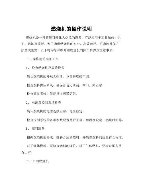
燃烧机的操作说明燃烧机是一种将燃料转化为热能的设备,广泛应用于工业加热、烘干、熔炼等领域。
为了确保燃烧机的安全、高效运行,正确的操作方法至关重要。
以下将为您详细介绍燃烧机的操作步骤及注意事项。
一、操作前的准备工作1、检查燃烧机及周边设备确认燃烧机的外观无损坏,各部件连接牢固。
检查燃料供应系统,确保管道无泄漏,阀门开关正常。
检查通风系统,保证风道畅通无阻。
2、电源及控制系统检查确认燃烧机的电源连接正常,电压稳定。
检查控制系统的各项参数设置是否正确,如温度设定、燃烧时间等。
3、燃料准备根据燃烧机的要求,准备合适的燃料,并确保燃料的质量符合标准。
对于液体燃料,要检查燃料的液位;对于气体燃料,要检查压力是否正常。
二、启动燃烧机1、开启通风设备先启动通风机,使炉膛内形成良好的通风环境,排除残留的可燃气体。
2、点火操作按照燃烧机的点火方式(电子点火或人工点火)进行操作。
点火时要注意观察火焰的形成情况,确保点火成功。
3、调节燃料供应点火成功后,逐渐增加燃料供应,使火焰稳定燃烧。
注意调节燃料供应的速度,避免火焰突然变大或变小。
三、运行中的监控1、火焰监测定期观察火焰的颜色、形状和稳定性。
正常的火焰应该是蓝色、清晰、稳定的。
如果火焰出现异常,如发黄、冒烟、闪烁等,应及时调整燃烧参数或采取停机措施。
2、温度监控通过温度传感器监测炉膛内的温度,确保温度在设定范围内。
如果温度过高或过低,要及时调整燃料供应和通风量。
3、压力监控对于气体燃料,要监测燃料的压力,确保压力稳定。
对于液体燃料,要注意油泵的工作压力。
4、运行声音监测倾听燃烧机运行时的声音,如有异常噪音,应停机检查。
四、停机操作1、逐渐减少燃料供应先缓慢减少燃料的供应量,使火焰逐渐变小。
2、关闭燃料供应当火焰完全熄灭后,关闭燃料供应阀门。
3、停止通风设备待炉膛冷却一段时间后,停止通风机运行。
4、清理与维护停机后,清理燃烧机表面的灰尘和杂物。
定期检查燃烧机的各部件,如喷油嘴、电极等,如有磨损或损坏,及时更换。
LAMTEC控制方案 FMS混烧方案

FMS混烧控制系统当下有很多需要混烧的需要,比如工业生产中的废气、废液,这些产品不能直接排放,要么回收处理,要么利用其可燃的特点,使其燃烧为工厂生产需要的热量提供能源。
在作为燃料的时候,又由于其产量不稳,热值有变化,对锅炉和燃烧机(尤其是后者)有要求,锅炉对外的功率输出是根据生产的需要而定,不能断续或者滞后,而这些废气废液燃料的供应有可能和热能的需求不同步,所以混烧对于这种工矿是合适的,如有废气废液,则优先燃烧,如果供应量不足,则需要常用燃料(天然气或轻油)补充,甚至在这些废料燃尽之后,要切换到后者进行独立燃烧。
那么这些废气废液可以单独燃烧,也可以与常规燃料混烧,在混烧的时候,需要对掺混比例进行控制,尽管固定比例比较好控制,但是很多用户更希望用可变比例,尽量多烧废气废液,少烧常规燃料,这就是对燃烧机的控制系统有了更高的要求,既要实现用户的自由调节掺混比(掺混信号可能来源于液位或者压力,不限于手动控制),又要燃烧的安全稳定。
这种控制方式,其实并不遥远,蓝姆泰克(Lamtec)早在上世纪九十年代就开始提供这种控制方案,并在德法意荷等国家大量应用,那么在今天,这些控制也在中国使用,只是深藏在化工厂的锅炉房,并不广为所见所知,那么下面有两个比较有代表性的方案,供大家了解。
方案一:两种燃料混烧(油气混烧为例)说明:1.上表配置仅供参考,具体项目具体分析。
2.FMS4 控制器第一通道与风机变频器相连,对风机进行变频控制,另外三个通道为TPS控制器。
3.FMS4控制器可以单烧油、单烧气、油气混烧(分别为油为主气为辅,气为主油为辅),外部开关量切换,燃料混合比例自由变化。
4.燃气模式,含有阀组检漏的测试程序,无需额外的检漏设备。
5.相应执行机器的选择,根据对应机构的扭矩阻力决定,视具体燃烧机的情况而定。
本方案中用于参考。
6.FMS4控制器直接使用F200K火检,也可以使用其他品牌火检的开关量信号。
7.把烟气中的氧气含量反馈给控制器,激活使用控制器内部的氧气含量控制功能,控制器自动修正空燃比,使得过氧含量保持在理想的范围内。
燃烧器操作手册
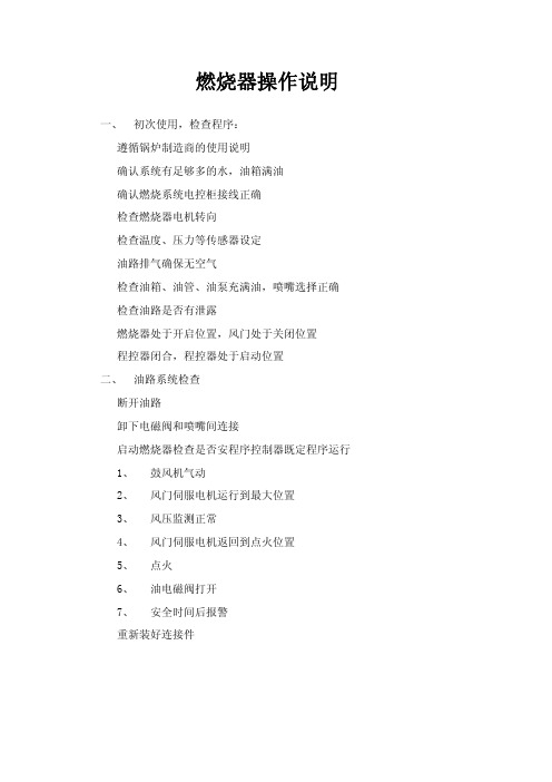
燃烧器操作说明一、 初次使用,检查程序:遵循锅炉制造商的使用说明确认系统有足够多的水,油箱满油确认燃烧系统电控柜接线正确检查燃烧器电机转向检查温度、压力等传感器设定油路排气确保无空气检查油箱、油管、油泵充满油,喷嘴选择正确检查油路是否有泄露燃烧器处于开启位置,风门处于关闭位置程控器闭合,程控器处于启动位置二、 油路系统检查断开油路卸下电磁阀和喷嘴间连接启动燃烧器检查是否安程序控制器既定程序运行1、鼓风机气动2、风门伺服电机运行到最大位置3、风压监测正常4、风门伺服电机返回到点火位置5、点火6、油电磁阀打开7、安全时间后报警重新装好连接件三、 比例调节器回油与空气流量调节卸下风门伺服电机与比例调节器上的连接,启动燃烧器,点火后手动设定燃烧器负荷在最小位置,检查燃油和风量配合效果。
顺时针转动= 增加风量逆时针转动= 降低风量注意:燃烧器启动后调节风压开关,如果设定值过高,风压开关会自动保护,设定风压保护值一定要合理。
测量点火位置油消耗量1、通过流量表2、根据供油压力和喷嘴型号按照曲线图测算调节点火位置油量1、若喷油量过低,将伺服电机逐步增大到规定值2、若喷油量过高,现将最低油量限位开关调低,再逐步降低风门伺服电机,直至达到规定值。
调整过程中注意燃烧器的燃烧情况,如有必要从新调整。
调整满负荷耗油量逐步增大风门伺服电机的位置直至满负荷,调整过程中观察火焰燃烧情况,如有必要从新进行调整。
测量满负荷位置油消耗量1、通过流量表2、根据供油压力和喷嘴型号按照曲线图测算调节满负荷油流量若满负荷油量过多,减小风门伺服电机开度,直至达到规定值注意:不允许通过调节连杆降低油流量,以免影响低负荷燃烧状况。
若满负荷油量过低,首先增大限位开关的位置,然后调节伺服电机的开度,直至达到规定值,调节过程中注意观察火焰燃烧情况,如有必要从新进行调整。
风量调节风门伺服电机出厂设定值为:满负荷时全开,低负荷时全关,未达到最佳的燃烧效果,应从低负荷位置逐步调整燃油与风量的配比。
- 1、下载文档前请自行甄别文档内容的完整性,平台不提供额外的编辑、内容补充、找答案等附加服务。
- 2、"仅部分预览"的文档,不可在线预览部分如存在完整性等问题,可反馈申请退款(可完整预览的文档不适用该条件!)。
- 3、如文档侵犯您的权益,请联系客服反馈,我们会尽快为您处理(人工客服工作时间:9:00-18:30)。
一、概述
1.1 缘起
1.2 目的
1.3 适用范围
二、lamtec燃烧机控制系统基本概述
2.1 燃烧机控制系统的作用
2.2 lamtec燃烧机控制系统的特点
2.3 lamtec燃烧机控制系统的组成
三、准备工作
3.1 检查操作手册和相关文件完整性
3.2 确保所有操作人员对lamtec燃烧机控制系统有基本的了解 3.3 准备所需的工具和设备
四、系统操作指南
4.1 启动系统
4.1.1 检查系统电源
4.1.2 检查燃烧机控制系统的连接
4.1.3 操作步骤
4.2 关闭系统
4.2.1 停止供电
4.2.2 完成系统关闭程序
4.3 系统维护
4.3.1 定期清洁检查
4.3.2 故障处理
五、应急处理
5.1 紧急停机
5.2 突发故障处理
5.3 安全事故处理
六、特殊操作指南
6.1 对不同燃烧机设备的lamtec燃烧机控制系统操作说明
七、注意事项
7.1 操作人员资质要求
7.2 操作环境要求
7.3 安全设施要求
八、附录
8.1 常见故障解决对策
8.2 操作人员通联方式
九、结语
随着工业自动化的发展,燃烧机控制系统在工业生产中的作用日益凸显。
而lamtec燃烧机控制系统作为目前市场上较为先进的一款系统,其在燃烧机运行和控制方面具有一定的技术优势和市场竞争力。
为了
更好地保障lamtec燃烧机控制系统的正常运行和安全使用,特制定本操作手册,以供相关操作人员参考。
本手册从lamtec燃烧机控制系统的基本概述开始,逐步介绍了准备工作、系统操作指南、应急处理、特殊操作指南、注意事项等内容,并
提供了常见故障解决对策和操作人员通联方式的附录。
在使用lamtec 燃烧机控制系统的过程中,操作人员应严格按照本操作手册的要求进
行操作,确保系统的安全、稳定和高效运行。
在我们希望用户在使用lamtec燃烧机控制系统时,能够仔细阅读本操作手册,严格按照操作流程进行操作,做到安全第一、预防为主,确
保lamtec燃烧机控制系统的正常运行,提高生产效率,保障生产安全。