紧急启停按钮JBF5181说明书_v1 120140901
消防报警控制器使用说明

消防报警控制器使用说明一、简介二、安装和连接1.安装位置应远离易燃物品和有潮湿、腐蚀性、震动等环境的地方。
2.将消防报警控制器固定在墙壁或其他固定物上,确保稳定。
3.连接电源和地线,确保电源供电稳定可靠。
三、操作面板1.启动和关闭消防报警控制器:按下控制面板上的启动或关闭按钮,操作灵敏、平稳。
2.显示屏幕:显示当前消防报警状态和相关参数,确保正常运行。
四、功能设置1.报警模式设置:根据需要选择手动、自动、远程等报警模式,确保安全。
2.报警参数设置:根据实际需求设置报警温度、湿度、烟雾等参数,保证准确报警。
3.报警器测试:按下测试按钮,确认报警器工作正常,能够及时报警。
五、报警处理1.报警自动处理:消防报警控制器可以自动启动报警装置和灭火系统,及时处理火灾事故。
2.报警响应处理:当控制器报警时,应立即启动应急预案,采取相应措施,确保安全。
3.报警记录和分析:消防报警控制器具备报警记录功能,可以记录报警时间、地点、类型等信息,便于事后分析与改进。
六、日常维护1.定期检查电源和电线接头:确保电源供电正常,电线连接牢固。
2.定期检查传感器:消防报警控制器的传感器可能会出现故障,需要定期维护和更换。
3.定期检查报警装置和灭火系统:保证报警装置和灭火系统处于正常工作状态。
4.定期清洁控制器面板和显示屏幕:避免灰尘和污垢影响正常操作。
七、注意事项1.操作人员必须经过专业培训,熟悉控制器的操作方法和注意事项。
3.严禁随意更改控制器的设置,以免影响正常运行。
4.在使用过程中如有异常报警或操作困难,应立即停止使用,并及时进行检修。
八、总结消防报警控制器是一种重要的消防设备,能够有效监测、控制和报警火灾事故。
正确使用和维护消防报警控制器,是保障人们生命财产安全的重要措施。
通过本文的使用说明,相信用户能够更加熟悉和了解消防报警控制器的使用方法和注意事项,提高火灾预防和应急处理能力。
应急发电机启停操作卡
执行情况
检查
和准备
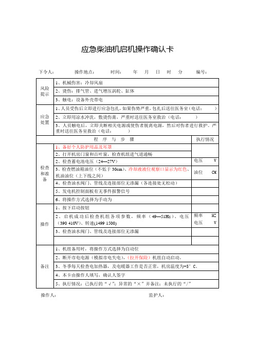
1、备好个人防护用品及耳罩
2、打开机房门窗和百叶窗,检查机组进气道通畅
2、检查蓄电池电压(24—27V)
电压V
3、检查燃油箱油位(不低于30cm)、冷却液液位观察口显示为红色、机油油位(上下线之间)
油位CM
4、检查油水阀门、管线及连接部位无渗漏(各连接处无松动)
5、发电机控制面板有无事件报警信号
6、将操作方式选择为手动为
操作
1、按下启动按钮
2、启机成功后检查机组各项参数,频率(49—51Hz)、电压(390-410V)、转速(1499-1500)
频率HZ
电压V
3、检查油水阀门、管线及连接部位无渗漏
备注
1、机组备用时,将操作方式选择为自动位
2、断开市电电源(模拟市电失电),(拉开保险)机组自动启动。
应急柴油机启机操作确认卡
下令人:操作地点:时间:年月日时分编号:
风险
提示
1、机械伤害:冷却风扇
2、烫伤:排气管、进气增压涡轮、缸体
3、触电:设备外壳带电
应急
处置
1、人员受伤后立即进行应急包扎,如果伤势严重,包扎后送往医务室(电话:)
2、立即用凉水冲洗,敷烫伤膏,严重时送往医务室救治(电话:)
3、人员触电后,立即关断相关电源或使伤者脱离电源,然后对伤者进行救护。严重时送往医务室救治(电话:)
4、进入机房要带好耳罩及对讲机。√”;异常的“×”并备注;未执行的“/”。
5、停机5分钟后停止运行
操作人:监护人:
频率HZ
电压V
2、检查蓄电池电压(24—27V)
电压V
3、检查燃油油位(不低于2/3CM)、机油油位(上下线之间)
JBF5014型气体灭火控制器火灾报警控制器使用说明书

气体灭火控制器火灾报警控制器(联动型)JB-QB-JBF5014使用说明书北大青鸟环宇消防设备股份有限公司目录第一章系统概述............................................ 错误!未定义书签。
1. 产品特点 (3)2. 技术特性 (4)3. 外形尺寸 (4)4. 系统组成 (5)5. 兼容设备目录 (5)第二章安装 (6)1. 开箱检查... ... ... ... ... ... ... ... ... ... ... ... ... ... ... ... ... ... (6)2. 安装 (6)3. 接线说明 (7)第三章界面显示 (9)第四章报警显示 (12)1. 正常状态 (12)2. 火警状态 (12)3. 启动状态 (13)4. 反馈状态 (13)5. 故障状态 (14)6. 屏蔽状态 (14)第五章操作 (15)1. 回路部件登记/查询 (15)2. 设置手自动控制状态 (17)3. 设置灭火自动方式 (18)4. 设备手动启动/停止 (19)5. 设置运行模式 (20)6. 现场部件设置/查询 (21)7. 灭火区设置/查询 (22)8. 多线检测设置/查询 (23)9. 联动编程设置/查询 (24)10. 汉字注释信息设置/查询 (25)11. 组网设置/查询 (26)12. 部件屏蔽/解除 (27)13. 设置时间 (28)14. 控制器自检 (28)15. 开关打印机 (29)16. 打印历史记录 (29)17. 浏览回路状态信号 (30)18. 多线联动区启动/停止 (31)19. 气体灭火区启动/停止 (32)20. 打印机操作 (33)第六章故障分析与排除 (34)第七章保养维修 (34)第八章附录 (35)附录联动编程语句语法规则 (35)第一章系统概述JB-QB-JBF5014型气体灭火控制器/火灾报警控制器(联动型)是青鸟公司推出的新一代集气体灭火功能和火灾报警功能于一体的控制器,可配接青鸟公司所有现场产品,应用于中小型场所,计算机室、图书馆等需要进行气体灭火控制的场所。
急停开关功能及设计原理说明书

Emergency stop switches,generally referred to as E-Stops,ensure the safetyof persons and machinery and provide consistent,predictable,failsafe controlresponse.A wide range of electrical machinery must have these specializedswitch controls for emergency shutdown to meet workplace safety andestablished international and U.S.regulatory requirements.E-Stops–criticalhuman machine interface(HMI)devices–differ from simple stop switches(that merely turn equipment off)in that they offer"foolproof"equipmentshutdown.This is accomplished through advanced switch design thatrequires a twist,pull,or key to release electrical contacts to allowmachinery restart.E-Stops are generally designed for failsafe operation sothe stop command has priority over the sustainingfunction.This has led to innovative switch designs thatprevent"blocking"(wanton or accidental obstructionof the actuator with foreign objects)and"teasing"(which could result in premature or unreliable action).Switch companies also are developing new solutions toproblems that arise when contact block and actuator areimproperly installed or separated because of vibrationor other malfunction.E-Stops are critical to the humanmachine interface(HMI).An E-Stop must be initiated by a single human action using a manual control device.Safe Emergency StoppingAccording to international standards,the emergency stop function must be initiated by a single human action using a manually actuated control device.The E-Stop function must be operational at all times and designed to stopthe machine without creating additional hazards.Resetting the electrical system can only be done by first releasing the E-Stopthat was originally activated.If E-Stops were activated at multiple locations,all must be released before machinery restart.It should be noted thatresetting E-Stops does not in itself restart the machinery;it only permits restarting through normal procedures appropriate for the machinery involved.Ergonomic,electrical,mechanical,and color requirements for E-Stops are quite specific.The E-Stop control,commonly a distinctive pushbutton switch or "mushroom type"pushbutton(although wires,ropes,bars,handles,or foot pedals are sometimes employed),must use direct mechanical action with mechanical latching.When the E-Stop is activated(pushed),it permanently opens the electrical contacts through a latching mechanism.To close the electrical contacts and allow machinery restart,the E-Stop actuator mustbe manually unlatched with a twist or a key release.Some E-Stop actuatorscan simply be pulled to close the electrical contacts.This approach may beless desirable from a safety standpoint than a twist or key release,which requires a more deliberate action by an operator.Designers should be aware of international and U.S.standards and regulations that impact the design and use of E-Stops.Selecting the Right E-Stopfor Your ApplicationBecause of the confusing array ofE-Stops available,it is important tounderstand the design basics thatcontribute to high-quality,ergonomicswitch design.EAO is a leader inHMI Components and Systems,including innovative,rugged,reliable,and affordable E-Stops that meetor exceed international andU.S.standards.One of the first steps is determiningwhere the E-Stop fits within yourmachine control system and whetheryour particular application requiresCategory0or Category1typeemergency shutdown.The intendedapplication often determines theplacement,size,electrical specifications,mechanical characteristics,ergonomics,color/legends,and number of E-Stopsrequired.So a thorough understandingof the machinery and associatedcontrol systems is key to making theright E-Stop choice.A second,and equally important step,is determining what international andE-Stops may require shorter behind-panel depth.Designed for rough dutyRobust,heavy-duty construction is the hallmark of the original22.5mm switches. Many,like the EAO Series04E-Stops,have stackable contact blocks,optional key release actuators,and mounting options for22.5mm panel openings.This EAO series is rated at up to10A,600VAC,has silver contacts with available gold over silver or silver over palladium contacts,and silver-plated screw terminals with available quick-connect terminals.Smaller mounting footprintModern applications often demand a slimmed down E-Stop with16mm mounting.Innovative products,like the EAO Series61,are now available with an actuator shape that prevents blockage from foreign objects,a black indicator ring visible from long distances,and available key release actuators.This EAO series is rated at5A,250VAC,and has a choice of silver or gold contacts,screw or solder quick-connect terminals.Short behind-panel depthNewer electronic applications are requiring E-Stops with shorter behind-panel depth.EAO's Series84E-Stop,for example,features a very short behind-panel depth(18mm maximum),single"mono-block"construction,22.5mm mounting, and available LED illumination that is visible from the side as well as front of the actuator.This series is rated at3A,120VAC and1.5A,240VAC,has gold contacts, quick-connect/solder printed circuit board terminals,and ribbon cable terminals.A22.5mm switch must bedurable and rugged.Today's applications often require a slimmer footprint for16mm mounting.U.S.standards,performance ratings, and codes apply for your application. Requirements vary by industry segment, so standards for E-Stops used on transportation vehicles may differ significantly from those used on process machinery or medical equipment and will be governed by different regulatory bodies specific to those segments. Regulatory bodies may also specify size,color,legend,contact terminals,etc.It is then useful to construct or consult an existing E-Stop series selectorchart(often supplied by vendors).For example,EAO provides a chart thatallows easy comparison of key designfactors for its multiple E-Stop series(see Figure1).You can select panelopening size,type of actuator,typeand number of contact blocks,connectors,colors,and maximumelectrical rating to come up with oneor more appropriate models.Like many vendors,EAO provides specialenclosures,switch guards,palm guards,custom labeling,and other accessoriesto complete virtually any E-Stopapplication.Some accessories maybe specified by industry standards,such as the SEMI standards forsemiconductor fabrication equipmentthat mandate the use of palm guards.EAO and other vendors also offerservices to assist customers in thedesign,engineering,and productionof HMI systems,integrating E-Stops.1EMERGENCY-STOPPUSHBUTTON ACTUATORActuators should be precision molded from high quality polymeric materials to assure a mechanical life in excess of 6,050operations as required by industry standards,including EN IEC 609475-5,paragraph 7.3.3.In real life,E-Stops generally exceed 250,000operations.Actuators can be “tease-proof”,twist-to-release,and foolproof in design.Actuators can also bepushbutton,mushroom,or key release.SEALINGMany E-Stops are sealed to IP 65oil and watertight standards.FRONT PLATEFront plates can be designed to conform to color and legend standards.FIXING NUTE-Stops have a variety of mounting options,for use in 22.5mm or 16mm panel openings.SWITCHING ELEMENTE-Stops typically offer a range of contact options including gold over silver or silver over palladium,and silver-plated screw terminals with available quick-connect terminals.2345ApplicationsVirtually all industry segments–from machinery, instrumentation,medical treatment and diagnostic,lifting/moving,and transportation–mandate E-Stopsfor safe operation.Designers need to have a thorough knowledge of E-Stop fundamentals,E-Stop switch characteristics and capabilities,and the internationaland U.S.standards and compliance requirements that apply to their application areas.E-Stops are required on all machinery independent ofthe type of energy used to control the function exceptfor machines in which an E-Stop function would not lessen the risk.An E-Stop switch is intended to be one part ofa comprehensive safety system,so the equipment designer must also consider safety functions,such as reversal or limitation of motion,deflection,shielding,braking,or disconnecting,that are not specifically addressed in this paper.Primary application areas where electrical machinery is safeguarded with E-Stop technology include:X-ray EquipmentCabinet x-ray systems used for diagnostic and therapeutic medical applications,industrial non-destructive inspection and thickness gauging,security inspection of baggage,and other imaging are closely regulated for operational safety.E-Stops are covered by standards and regulationsof the FDA Department of Health and Human Services.The key document is CFR Title21,Part1020–Performance Standards for Ionizing Radiation Emitting Products,section40, which requires accessible emergency stop switches and keyed lock-out switches to disable the system.Standard feature Available on requestFigure1–E-Stops selector chart by EAO SeriesFigure 2–International standards that apply to Emergency Stops vs.Stop SwitchesDepending on design and application requirements,many E-Stops are listed as UL category NISD emergency stop devices.This rating covers two categories of E-Stop function as defined in ANSI/NFPA 79,Electrical Standards for Industrial Machinery (ANSI is the American National Standards Institute and NFPA is theNational Fire Protection Association):1.Stop Category 0–Immediate removal of power to the machine or mechanical disconnection (de-clutching)of hazardous elements.2.Stop Category 1–Controlled stop with power available to stop themachine followed by removal of power when the stop is achieved.The emergency stop actuator provided in these devices must be a self-latching type.E-Stops with this rating have been reviewed for their functionality in addition to fire and electric shock safety.Emergency StopStop Switch Not defined Not defined Not definedNot definedNot necessaryNot defined Not definedNot defined,but usually realized by turning a key,by rotation of the button in thedesignated direction,or by a pulling motion.Not defined Not definedNot definedGeneral Color of actuator Actuators of emergency switching off devices shall be colored RED.•EN IEC 60947-5-5§4.2.1•EN 60204-1§10.8.3•DIN EN ISO 13850§4.4.5Actuator/BackgroundWhen a background exists behind the actuator,and as far as it is practicable,it shall be colored yellow.•EN IEC 60947-5-5,4.2.1•EN 60204-1,10.8.3•DIN EN ISO 13850§4.4.5Inscription of actuator The direction of unlatching shall be clearly identified when resettingis achieved by rotation of the button.•EN IEC 60947-5-5§4.2.1Electrical requirements Utilization categories The utilization categories shall be AC-15and/or DC-13and/or DC-14in accordance with EN 60947-5-1.•EN IEC 60947-5-5§5.1Direct opening action All normally closed contact elements of an emergency stop device shall have a direct opening action (positive opening action).•EN IEC 60947-5-5§5.2Latching It shall not be possible for the emergency stop device to latch-in without generating the emergency stop signal.•EN IEC 60947-5-5§6.2.1Resetting Resetting of the emergency stop shall only be possible as the result of a manual action at the location where the emergency stop was initiated.•EN ISO 13850,4.4.4Resetting The resetting of the latching means shall be by turning a key,by rotation of the button in the designated direction,or by a pulling motion.•EN IEC 60947-5-5§6.3.1Testing Robustness of A button actuator shall withstand a torque as specified below,in both directions of latched a button actuatorand unlatched positions,where the resetting action requires rotation of the push-button.•EN IEC 60947-5-5§7.3.2ØForce Torque16mm 80N 1.6Nm 22mm 110N 2.2Nm 30mm 150N 3.0Nm Durability testThe test shall consist of 6,050cycles in which latching and resetting of the actuator occurs during each cycle.The movement and actuating forces shall be consistent throughout the test.Monitoring of these parameters shall be carried out to ensure consistency.•EN IEC 60947-5-5§7.3.3NormsMandatory standards•EN IEC60947-5-5(International Standard)•EN ISO 13850(Safety of Machinery)•EN 60204-1(Safety of Machinery)Once you understand the E-Stop function and relevant standards, codes,and compliances you can determine the appropriate device.EAO Switch Corporation 98Washington Street Milford CT06460 T:(203)8774577 F:(203)8773694E-mail:******************* Member of the EAO Group Future of the TechnologyThe pace of change in E-Stop technology is steady,not revolutionary.By their nature,these devices must be recognizable,reliable,and rugged.They have a straightforward function:instantly shut down equipment with a simple pushof a(usually)bright red actuator.For safety,reactivation of the switch requires twisting or pulling the actuator by hand or,for even more security,unlockingit with a key before machinery can be restarted.Established standards,function, and familiarity dictate a certain beneficial inertia in new E-Stop developments.Many advances are driven by norm changes for E-Stops,such as DIN EN ISO 13850:2008that now requires mechanical latching and manual resetting ofE-Stops.Most research and development is aimed at improving the safety and reliability of the switches themselves and expanding their roles as lockout devices in some worker safety applications.One area of current interest is making sure that the E-Stop itself will“failsafe”should the actuator and contact block be separated.The contact block has normally closed contacts that allow power to flow to the machinery.Pushingan E-Stop separates the spring-loaded contacts,and mechanical latching keeps them open,stopping the machinery.But what happens if the actuator separates from the contact block or the latching mechanism fails?Separation of the contact block from the actuator renders an E-Stop ineffective. Current solutions include mono-block or unibody switches with a one-piece actuator/contact block,as well as switches with failsafe contact blocks that automatically cause machinery shutdown if the actuator and contact blockare separated.Other advances are application-driven.EAO's Series84E-Stops,for example,were developed for hand-held enclosures with slim behind-panel depth for robotics applications.These versatile E-Stops also are used in pendant controls for lifting and moving machinery.Application requirements have also created a wide variety of available optional features and accessories for most E-Stop products–illumination,protective rings,enclosures,guards,legend plates,etc.–that add to the functionality and safety of E-Stop installations.E-Stops will continue to evolve to meet new standards and new applications. For designers,the most important considerations in making the right design decisions are a thorough understanding of E-Stop function;a grounding inthe standards,codes,and compliances involved;proper selection of devicesthat meet or exceed the application requirements.。
JBF5014型气体灭火控制器火灾报警控制器(联动型)使用说明书(修订)V1.1

气体灭火控制器火灾报警控制器(联动型)JB-QB-JBF5014使用说明书北大青鸟环宇消防设备股份有限公司目录第一章系统概述 (3)1. 产品特点 (3)2. 技术特性 (4)3. 外形尺寸 (4)4. 系统组成 (5)5. 兼容设备目录 (5)第二章安装 (6)1. 开箱检查... ... ... ... ... ... ... ... ... ... ... ... ... ... ... ... ... ... (6)2. 安装 (6)3. 接线说明 (7)第三章界面显示 (9)第四章报警显示 (12)1. 正常状态 (12)2. 火警状态 (12)3. 启动状态 (13)4. 反馈状态 (13)5. 故障状态 (14)6. 屏蔽状态 (14)第五章操作 (15)1. 回路部件登记/查询 (15)2. 设置手自动控制状态 (17)3. 设置灭火自动方式 (18)4. 设备手动启动/停止 (19)5. 设置运行模式 (20)6. 现场部件设置/查询 (21)7. 灭火区设置/查询 (22)8. 多线检测设置/查询 (23)9. 联动编程设置/查询 (24)10. 汉字注释信息设置/查询 (25)11. 组网设置/查询 (26)12. 部件屏蔽/解除 (27)13. 设置时间 (28)14. 控制器自检 (28)15. 开关打印机 (29)16. 打印历史记录 (29)17. 浏览回路状态信号 (30)18. 多线联动区启动/停止 (31)19. 气体灭火区启动/停止 (32)20. 打印机操作 (33)第六章故障分析与排除 (34)第七章保养维修 (34)第八章附录 (35)附录联动编程语句语法规则 (35)第一章系统概述JB-QB-JBF5014型气体灭火控制器/火灾报警控制器(联动型)是青鸟公司推出的新一代集气体灭火功能和火灾报警功能于一体的控制器,可配接青鸟公司所有现场产品,应用于中小型场所,计算机室、图书馆等需要进行气体灭火控制的场所。
紧急停止按钮指南说明书

05.2020ContactSchmersal USA 15 Skyline DriveHawthorne, NY 10532 Tel: 914-347-4775 Fax: 914-347-1567E -mail:**********************Schmersal Canada29 Centennial Road, Unit 1 Orangeville, ON L9W 1R1 Tel: 519-307-7540 Fax: 519-307-7543E -Mail:*************************Tech Briefs:Emergency Stop ButtonsWhitepaper:Emergency Stop DevicesVisit our website for a PDF CopyOverviewAccording to OSHA, ANSI and relevant ISO regulations every machine is required to have a means to immediately remove all hazardous energy in the event of an emergency. In most all industrial machines this is achieved by the use of an Emergency Stop (E -Stop) pushbutton.NFPA79 and ISO 13850 detail the physical characteristics of a push button E -Stop, which will include a RED mushroom operator head with YELLOW background. It must also be self -latching, meaning that once actuated the Emergency Stop will remain in the actuated state until a voluntary and deliberate action is performed, such as twisting and/or pulling of the palm button for reset. In addition, this resetting of the E -Stop alone should not resume operation; instead a second deliberate action is needed, such as the pressing of a RESET button.OSHA and standards such as IEC 60204-1 state that an Emergency Stop must be readily accessible to the operator. This means that every operator station or any area of the machine worked on which is considered part of the normal operating procedure needs a means for an emergency stop. It should be unobstructed and easily accessible without having to reach over, under or around to actuate.BDF100-NHK -G -ST E -STOP 201 ESTOP -MBGAC311 Various ModelsSchmersal offers a number of complete E -Stop pushbutton kits that satisfy all relevant require-ments. They include the operator, contact blocks, and enclosure.BDF100-NH -G -STE -Stop without protective collarBDF100-NHK -G -STE -Stop with protective collarE -STOP201Plastic pushbutton in plastic enclosure (pre -assembled)ADRR40RT 40mm button CLP101 1NC contact (x2) MBKAC311YE EnclosureAdditional contact blocks available: CLP101 1NC contact CLP110 1NO contactE -STOP -MBGAC311 Metal pushbutton in metal enclosure (kit)EDRR50RT 50mm button EF220.1 2NC contact EFR Spring element MBGAC311YE EnclosureAdditional contact blocks available: EF220.2 2NC EF303.2 1NO/1NCE -STOP KITMetal pushbutton for panel mounting (kit)EDRR40RT 40mm button EF303.1 1NO/1NC contact EF303.2 1NO/1NC contact EFR Spring Element MDP8.2 Yellow plateCompatible Safety Controllers SRB -E -201LC SRB -E -322ST SRB -E -201ST SRB -E -402ST SRB -E -301ST SRB -301MC SRB -E -212STE -STOP KITAvailable LiteratureCommand and Signaling Devices Complete E -STOP KITThe E -STOP KIT includes all the components necessary for a panel -mounted emergency stop pushbutton. They are delivered in a single box.It includes:A 40 mm diameter aluminum operator head with mounting block.Two 1 NO & 1 NC contact blocks.A spring element for latching and reset function.A round yellow metal plate with adhesive on the back.IP69K Rated E -StopSchmersal offers an E -Stop pushbutton that meets IP69K sealing requirements … tolerating high temperature (up to 175°F) steam or water wash downs at pressures up to 1450 psi. The NDRR50RT offers a 50 mm wide, thermoplastic head and modular contact block system.This E -Stop is ideal for applications where hygienic conditions are critical (food processing, medical equipment, meat packaging and pharmaceutical manufacturing). It was specifically designed with smooth surfaces to reduce the accumulation of process substances, dirt and/or bacteria.。
操作说明

消防报警控制器操作说明控制室人员应认真做好值班记录,如发生报警,应先按下控制器上的“消音”键,根据控制器报警信息察看发生火警部位,与报火警现场联系或到现场确认是否有火警,根据现场实际情况采取相应措施。
火情确认后应立即进行处理。
处理完毕后做执行记录,然后按“复位”键消除。
如确认报警为误报,在记录完毕后可将报警的控制器或模块关闭,立即通知我公司技术服务部修理。
不得擅自拆开或维修。
值班人员可根据控制器提供的信息,作出相应处理(火警时火警指示灯亮、故障时故障指示灯亮)。
一、火警处理:当发生火警时,首先按“消音”键终止报警声,然后根据控制器的报警信息检查发生火警的部位,确认是否有火灾发生。
一旦有火情应根据火情冷静的采取相应的措施。
1、1)在手动消防启动盘上启动着火层的声光迅响器,使其发出火警声光提示。
2)切断非消防电源(正常照明用电)。
3)着火层有水流指示器、压力开关报动作时控制室人员启动喷淋泵,进行补水灭火。
4)降落防火卷联门。
2、利用现场灭火设备灭火(如:灭火器、消火栓等)。
3、必要时及时拨打“119”报警。
4、确认火灾发生时,可将报警控制器打入自动状态。
此时控制器将由自动程序控制,并保证消防重要设备(风机、水泵、控制室等)用电,使其达到消防使用功能。
※正常监控状态下,不应该将控制器打入自动状态。
以免误报造成不必要的损失和人员恐慌。
※消防控制的附属设备箱必须在自动状态方可联动。
二、误报处理:1)查误报部位是否灰尘过大,确认是由于人为或其它因素造成误报警,按“复位”键和“确认”键恢复正常状态。
观察是否还会误报,仍误报可将其隔离并通知安装单位进行维修。
2)喷淋系统误动作时,及时关闭该层信号蝶阀并查明原因。
修复系统后打开蝶阀,使系统正常工作。
洒水喷头应在零上4℃环境中工作,温度过低会冻裂喷头,。
三、故障处理:控制器发生故障报警时,(故障灯亮)查看其信息并将其隔离,通知维修人员维修。
1.隔离操作:按“隔离”键+“确认”键屏幕出现“请输入隔离设备号”,然后输入设备号码(6位),按“T AB”键,使光条移到设备类型后,看其报警设备的设备类型(如光电感烟输入“03”,手动报警按钮输入“11”等)输入其设备类型代码,再按确认键,隔离灯点亮操作完毕。
紧急启停按钮说明书
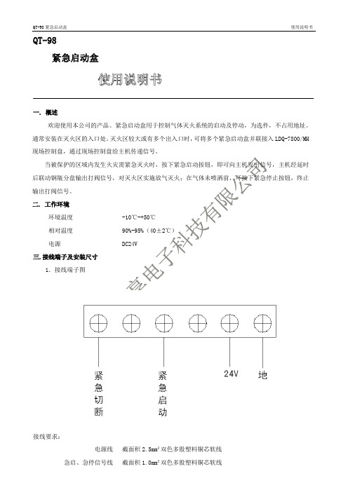
QT-98
紧急启动盒
使用说明书
一. 概述
欢迎使用本公司的产品。
紧急启动盒用于控制气体灭火系统的启动及停动,为选件,不占用地址。
通常安装在灭火区的入口处。
灭火区较大或有多个出入口时,可将多个紧急启动盒并联接入LDQ-7800/MH 现场控制盘,通过现场控制盘给主机传递信号。
当被保护的区域内发生火灾需紧急灭火时,按下紧急启动按钮,即可向主机发出信号,主机经延时后联动钢瓶分盘输出打阀信号,对灭火区实施放气灭火;在气体未喷洒前,可按下紧急停止按钮,终止输出打阀信号。
二. 工作环境
环境温度 -10℃-+50℃
相对温度 90%-95%(40±2℃)
电源 DC24V
三.接线端子及安装尺寸
1.接线端子图
接线要求:
电源线截面积2.5mm²双色多股塑料铜芯软线
急启、急停信号线截面积1.0mm²双色多股塑料铜芯软线
2.安装尺寸
外形尺寸:141mm(高)×128(宽)×60mm(厚)。
- 1、下载文档前请自行甄别文档内容的完整性,平台不提供额外的编辑、内容补充、找答案等附加服务。
- 2、"仅部分预览"的文档,不可在线预览部分如存在完整性等问题,可反馈申请退款(可完整预览的文档不适用该条件!)。
- 3、如文档侵犯您的权益,请联系客服反馈,我们会尽快为您处理(人工客服工作时间:9:00-18:30)。
紧急启停按钮JBF5181
(安装使用说明书)
一、 安装说明:
本按钮专用于气体灭火控制系统,使用无极性两总线回 路,并将现场使用状态发送给气体灭火控制器。
安装通 用于86预埋盒,也可采用明装接线盒安装。
1. 取下A 处固定螺丝,将盒体与底座分离。
2. 用螺钉将底座固定在墙内预埋盒或明装接线盒上。
3. 按接线示意图连接好总线。
4. 将盒体上部紧扣底座上部,再将A 处固定螺丝拧紧 即可
二、 接线示意图
1. 本按钮属于编址现场设备,采用无极性两总线回路, 同一分区灭火分区可以接单个或多个启停按钮。
A 2. 接线端子如接线示意图所示。
采用RVS 1.5mm 双绞 线连接到总线回路,对应L1,L2端子标识连接到无极 性两总线回路上。
装配图 三、 使用说明:
1. 使用编码器对设备进行编码,编址范围1-79,一 路总线回路中最多可挂接6个紧急启停按钮。
2. 按接线示意图连接总线,使用气体灭火控制器对本 按钮进行注册。
3. 通过气体灭火控制器检查注册成功与否,及设备是 否运行正常。
4. 压碎“压下喷洒”透明罩,按下“压下喷洒”按钮, 左侧红灯亮,表示喷洒启动按钮处于按下状态。
5. 压碎“停止”透明罩,按下“停止”按钮,右侧绿 灯亮,表示喷洒停止按钮处于按下状态。
6. 启动后复位:在产品左侧开有钥匙孔。
用复位专用 钥匙插入钥匙孔内,按图示方向旋转45°,即可复 位。
四、 技术参数:
接线示意图 五、 装箱清单:
L1 L2。