MTL5000-Rev-M MTL5000系列安全栅选型手册
mtl安全栅组态中文说明书

mtl安全栅组态中文说明书
MTL安全栅组态中文安全说明书
1、隔离式安全栅应安装在非危险场所。
2、隔离式安全栅通往现场(危险场所)的软铜导线截面积必须大于0.5mm。
3、连接导线的绝缘强度大于500V。
4、隔离式安全栅本安端(有蓝色标记)和非本安端电路配线,不得接错和混淆。
本安导线宜选用蓝色作为本安标记。
本安导线和非本安导线在汇线槽中应分开铺设,采用各自保护套管。
5、隔离式安全栅与一次仪表组成本安安全防爆系统时,必须经国家指定的防爆检验机构检验认可。
6、对隔离式安全栅进行单独通电调试时,必须注意隔离式安全栅的型号、电源极性、电压等级及隔离式安全栅外壳接线端上的标号。
7、严禁用兆欧表测试隔离安全栅端子之间的绝缘性。
若要检查系统线路绝缘性时,应先断开全部隔离式安全栅接线,否则会引起内部器件损坏。
8、凡与隔离安全栅相连接的现场仪表,均应为有关防爆部门进行防爆试验并取得防爆合格证的仪表。
MTL5500系列安全栅修改配置-杨红14年04月

MTL5500系列安全栅修改配置以MTL5575为例加以简要说明(输入PT100、三线制,输出4~20mA,量程范围0~200℃):1、安装调试软件PCS45_Install_V3.11以及电缆驱动PCS45_USB_Driver2.08.14,电缆驱动需将电缆连接到电脑方可安装。
2、将电缆一端接电脑(USB),另一端接到MTL5575模块(圆头)上的CONFIG端口。
接通模块电源(DC24V,14为正端,13为负端),将模拟电阻器接到相应的端子(一端接到3,另一端引出两根线分别接到1和4);待模块上的指示灯PWR黄灯由闪烁变成常亮即可开始连线软件修改配置。
3、双击图标打开软件,输入密码“MTL”,显示“Password input ok.Allfunctions enabled密码输入ok。
所有功能启用”。
4、菜单“Options选项”-“Port selection端口选择”进行端口设置,如下图:点击“Accept接受”即可。
5、菜单“File文件”-“New新建”-“Select device选择设备”,勾选“MTL4575”,点击“Accept接受”。
6、菜单“Connection连接”-“Establish建立”,跳出对话框“Confirm确认”:“There is device data in the memory.Should the data be overwriten?有设备内存中的数据。
数据应该写入吗?”,点击“OK”连接模块与软件;跳出画面“Establish建立”:“Data exchanging.Please wait…数据交换。
请稍等…”,如下图:7、菜单“Device data设备数据”-“Input config.输入配置”-“Configure inputdata配置输入数据”,在“RTD types RTD类型”处勾选“Pt100”,在“wiring”处勾选“3-wire”,其余的为默认;单击“Accept接受”,待修改完毕点击“Close”关闭窗口,输入数据即配置完毕。
MTL安全栅的技术说明

MTL安全栅的技术说明MTL是世界著名本安仪表品牌,本安技术多年居领先地位,MTL仪器仪表(中国)有限公司(以下简称MTL)是MTL公司全球业务的一部分,多年来在中国所有的大型石化企业的装置大量应用,占主装置进口安全栅份额的70%以上。
尤其在近几年百万吨乙烯和千万吨炼油项目中90%均采用MTL安全栅,如兰州乙烯,茂名乙烯,赛科100万吨乙烯,福建100万吨乙烯一体化(含1000万吨炼油),海南1000万吨大炼油,青岛1000万吨大炼油,燕山石化1000万吨炼油改造,广石化800万吨炼油,武石化800万吨炼油。
在这些大项目中,均采用DCS与安全栅整体采购,这样可以减少工作界面与中间环节,便于项目管理,提高工程效率,这种模式也是国际上正在流行的采购模式,说明中国的工程建设当正在引入先进的国际化工程理念。
在本项目中MTL可以提供成熟的、有丰富应用经验的底板安装方案,这是一种世界上最先进的接线和安装方式,优点在于:1.减少接线环节,减少故障点,提高系统可靠性。
2.节省机柜空间,减少机柜数量,利于控制室排布。
3.集成非常快捷,缩短开车调试周期。
4.便于系统运转后的日常维护和管理。
5.底板安装支持各家DCS厂商:Yokogawa, Honeywell, ABB, Foxboro, Triconex, Siemens,August Systems 。
6.已经取得IEC的SIL2认证,技术上亦可实现SIL3的安全标准。
为了更好地为中国的用户服务,MTL在上海和北京都配有丰富工程经验的高级应用工程师。
MTL引以自豪的是我们的生产效率和产品质量,但我们清醒地认识到在高速发展的工业领域,我们必须不断改进产品结构和提高质量,使MTL永远站在本质安全领域的前列,才能更好地服务用户。
P+F安全栅在国内使用故障的装置:1.2004年上海氯碱厂离子膜烧碱装置中P+F的温度变送器隔离栅使用时多次出现故障,更换过两次,给生产造成很大的影响。
变送器电流信号配电隔离安全栅

变送器电流信号配电隔离安全栅TM5000系列隔离式安全栅型号:变送器电流信号(带配电)隔离式安全栅TM5041,TM5043,TM5044给处于现场危险区域的变送器提供隔离的直流电源,并检测来自变送器的4~20mA电流信号,经过隔离、抗干扰抑制等处理后。
安全侧的控制系统或其他单元组合仪表输出直流电流或电压信号。
本隔离安全栅需要独立的直流供电,供电电源-输入-输出之间隔离。
供电电源电源电压:20~30VDC电源指示通电时,LED电源灯亮绿色电流消耗(24VDC供电时):〈50mA(1入1出)〈60mA(1入2出)〈110mA(2入2出)本安侧输入输入信号:变送器直流电流信号4~20mA输入阻抗:50Ω(1入1出,1入2出);100Ω(2入2出)给变送器的配电电压:≥16VDC(供电电源≥22VDC)最大输入电流限制:约24mA非本安侧输出输出电流:4~20mA,0~20mA,0~10mA输出电压:1~5v;0~5v,0~10v;其他指定电流电流输出允许负载:0~550Ω(满负载550Ω时,供电电源≥22VDC)电压输出阻抗:≤550Ω输出纹波:〈10mVp-p综合主要技术参数标准精度:±0.1%温度漂移:±0.015%/℃开机响应时间:<1s(10~90%)电源变化影响:±0.1%(20~30VDC允许电压范围)隔离能力:输入-输出-电源之间1.5Kv,1min,50Hz绝缘电阻:输入-输出-电源之间≥100MΩ/50VDC工作环境温度:-20-+60℃外形尺寸:厚度x高度x长度=16x116x110(mm)安全防爆认证参数:防爆等级标志:【Exia】IIC安全认证参数:Um=250V Uo=28V Io=93mA Po=0.65W Lo=2.4mA Co=0.03μF。
MTL安全栅

主要特点
13.符合FSM认证标准(MTL FSM), MTL是过程仪表设备供 应商中第一家取得该认证的厂家。对于安全完整性等级(SIL)认 证是对整个回路的考虑而不只是某个部件,而对于具体的部件 ,不同的计算方式得出的SIL等级也不同,通常需要提供基本数 据而不是SIL等级给ESD厂家计算整个回路的等级。(SIL)
主要特点
17. 安全栅和底板密集设计,减轻了重量,提高了安装密度。 安全栅厚度仅16mm,底板有4、8、16、24个组件等多种选 择。
客户化解决方案
主要特点
安全栅底板通过多芯插头及电缆直接与部分DCS I/O卡件连 接,省去DCS 端子板及传统的由安全栅到端子板的点与点连接 线,从而节省了机柜空间,简化了工程量,减少了人为错误, 降低了工程费用。
6、配ICS的一体化底板
安全栅类型
开关量输入:
MTL4501-SR 1ch DI failsafe solid-state output + LFD alarm MTL4510 4ch DI solid-state output MTL4510B 4ch DI multifunction solid-state output MTL4511 1ch DI relay output MTL4513 2ch DI solid-state output MTL4514 1ch DI relay output + LFD alarm MTL4516 2ch DI relay output MTL4516C 2ch DI with changeover relay output MTL4517 2ch DI relay output + LFD alarm
配Yokogawa ProSafe RS Safety System的一体化底板
MTL 5000系列安全栅样本说明
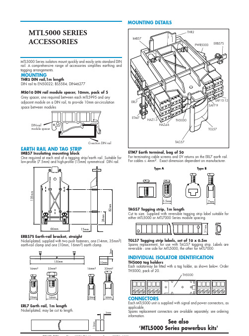
MTL5000 SERIESACCESSORIESMTL5000 Series isolators mount quickly and easily onto standard DINrail. A comprehensive range of accessories simplifies earthing andtagging arrangements.MOUNTING DETAILS16mm235mm222Type BType ATH5000 DIN-railSee also‘MTL5000 Series powerbus kits' MOUNTINGTHR2 DIN rail,1m lengthDIN rail to EN50022; BS5584; DIN46277MS010 DIN rail module spacer, 10mm, pack of 5Grey spacer, one required between each MTL5995 and anyadjacent module on a DIN rail, to provide 10mm air-circulationspace between modulesEARTH RAIL AND TAG STRIPIMB57 Insulating mounting blockOne required at each end of a tagging strip/earth rail. Suitable forlow-profile (7.5mm) and high-profile (15mm) symmetrical DIN rail.ETM7 Earth terminal, bag of 50For terminating cable screens and 0V returns on the ERL7 earth rail.For cables ≤4mm2. Exact dimension dependent on manufacturer.TAG57 Tagging strip, 1m lengthCut to size. Supplied with reversible tagging strip label suitable foreither MTL5000 or MTL7000 Series module spacing.TGL57 Tagging strip labels, set of 10 x 0.5mSpares replacement, for use with TAG57 tagging strip. Labels arereversible - one side for MTL5000, the other for MTL7000.INDIVIDUAL ISOLATOR IDENTIFICATIONTH5000 tag holdersEach isolatormay be fitted with a tag holder, as shown below. OrderTH5000, pack of 20.CONNECTORSEach MTL5000 unit is supplied with signal and power connectors, asapplicable.Spares replacement connectors are available separately; see orderinginformation.ERB57S Earth-rail bracket, straightNickel-plated; supplied with two push fasteners, one (14mm, 35mm2)earth-rail clamp and one (10mm, 16mm2) earth clamp.ERL7 Earth rail, 1m lengthNickel-plated; may be cut to length.MTL5000 SERIES ACCESSORIES ~RING TERMINALSRing terminal plugs are available for all of the popular modules in the MTL5000 series. The safe and hazardous area plugs are ordered seperately since the internal connections depend on the module type. Labels fitted on the side of each plug identify the terminal number with respect to the module and the standard tagging accessories can be used with the terminals fittedSPECIFICATIONRing Terminal dimensions3.5mm (M3.5) Internal8.5mm ExternalMechanical ProtectionIP20SafetyConforms to EN61010-1 Electrical standard and EN50020Intrinsic Safety standard. IS Certification is included in the MTL5000 Series ATEX approvals.DIMENSIONS (mm)ORDERING INFORMATIONNOTE:1- No earth terminal for earth leakage detection.2- No output 2.3- No voltage pulse or 3-wire voltage pulse.4- No HHC terminals.5- No trip B.SPECIFICATIONConstructionGlass reinforced polycarbonate base - DX070Glass reinforced polyester base - DX170, DX430Transparent polycarbonate lid ProtectionDust-tight and water-jet proof to IEC529:IP65Lid fixingCaptive fixing screwsWeight (excluding barriers/isolators) kgDX0700.8DX170 2.6DX430 4.1Items providedDIN rail - fittedETL7000 Earth terminals (2 x) - fitted "Take care IS" front adhesive label Cable trunking (except DX070)Note: Barriers or isolators are not included.MountingWall fixing lugs provided. For further details refer to INM5000.Tagging and earth railAccommodates MTL5000 Series accessories.Permitted locationSafe areaFM and CSA Div. 2, Class I (gases)Not Div. 2, Class II (dust ignition proof)Approximate capacities (on DIN rail between earth terminals)* Use these figures when IMB57 mounting blocks for tagging/earth are included.Ambient temperature limitsDependent on units fitted. See instruction manual INM5000.MTL5000 SERIES ENCLOSURESDIMENSIONS (mm) AND MOUNTINGDX430DX170MTL5000 isolatorsDX0704(2)*DX17010(8)*DX43026(24)*MTL5000 SERIES POWERBUS KITSPB - 8T,16T,24T,32TThe MTL5000 Series powerbus kit enables quick and easy wiring to power up to 32 MTL 5000 Series modules using a standard 24V power supply. Each powerbus kit includes 4 single ferrules, 4 twin ferrules and 2 insulation displacement connectors (Scotchlok).SPECIFICATIONAvailable in 4 different lengths:PB - 8T = 8 connectors and loops PB - 16T = 16 connectors and loops PB - 24T = 24 connectors and loops PB - 32T = 32 connectors and loopsCABLE PARAMETERSInsulation material :PVCConductor :24 strands of 0.2mm dia (0.75mm 2) standard copper Insulation thickness :0.5 to 0.8 mm Current rating :12A maxOperating temperature range :- 20ºC to +60ºCMax voltage drop on 32 modules drawing 130mA max :0.5VCHOOSING A POWERBUSChoose a powerbus where the number of power plugs is greater than or equal to the number of isolators to be powered and if necessary cut the powerbus to the required number of terminations.Note: To reduce the risk of excessive voltage drop or overcurrent do not connect powerbuses in series.MTL5099 DUMMY ISOLATORThe MTL5099 is used with other MTL5000 Series units to provide termination and earthing facilities for, unused cable cores from hazardous areas.SPECIFICATIONSee common specification belowTerminalFunction1Hazardous-area core2Hazardous-area core3Hazardous-area core4Hazardous-area core5Hazardous-area core6Earth7Safe-area core8Safe-area core9Safe-area core10Safe-area core11Safe-area core12Safe-area core MTL5000 SERIESCOMMONSPECIFICATIONConnectorsEach MTL5000 unit is supplied with signal and powerconnectors, as applicable.When using crimp ferrules for the hazardous and non-hazardous(safe) signal connectors the metal tube length should be 12mmand the wire trim length 14mm. For the power connectors themetal tube length should be 10mm and the wire trim length12mm.See INM5000 for recommended ferrules.Isolation250V rms between input, output and power supply terminals,tested at 1500V rms minimum between safe- and hazardous-areaterminals. MTL5073, output and power supply not isolated.Location of unitsSafe areaTerminalsAccommodate conductors of up to 2.5mm2stranded or single-coreMountingOn 35mm (top hat) rail toEN 50022–35 x 7.5; BS 5584;35 x 27 x 7.3 DIN 46277Ambient temperature limits–20 to +60°C (–6 to +140°F) operating–40 to +80°C (–40 to +176°F) storageHumidity5 to 95% relative humidityWeight110g approx (except where indicated)DIMENSIONSCABLE PARAMETERSTerminalFunction1Input –ve 2Input +ve3Earth leakage detection 10Normally-closed contact 11Common12Normally-open contact 13Supply –ve 14Supply +veThe MTL5011B enables a safe-area load to be controlled by a switch or proximity detector located in a hazardous area. A relay output is provided. Phase reversal control allows an alarm condition to be signalled for either state of the sensor. A selectable line fault detect (LFD) facility detects an open or short circuit in the field circuit.MTL5011B SWITCH/PROXIMITY DETECTOR INTERFACEsingle-channel, with line fault detection and phase reversalSPECIFICATIONSee also common specificationNumber of channelsOneLocation of switchZone 0, IIC, T6 hazardous area Div. 1, Group A hazardous location Location of proximity detectorZone 0, IIC, T4–6 hazardous area if suitably certified Div. 1, Group A hazardous location Safe-area outputOne relay with changeover contacts Hazardous-area inputInput conforming to NAMUR/DIN 19234 standards for proximity detectorsVoltage applied to sensor7 to 9V from 1k Ω±10%Input/output characteristicsNormal (reverse) phase:output energised (de-energised) if I in >2.1mA or R in <2k Ωoutput de-energised (energised) if I in <1.2mA or R in >10k ΩHysteresis: 200µA, typical Line fault detection (LFD)User-selectable, via switches on the top of unit. Line faults are indicated by an LED. A detected line fault de-energises the relay.Open-circuit alarm on if I in <100µA Open-circuit alarm off if I in >250µA Short-circuit alarm on if R in <100ΩShort-circuit alarm off if R in >360ΩNote: Resistors must be fitted when using the LFD facility with a contact input 500Ωto 1k Ωin series with switch 20k Ωto 25k Ωin parallel with switchPhase reversalUser-selectable, via switches on the top of unit.Relay typeSingle-pole changeover relayNote: reactive loads must be adequately suppressedRelay characteristicsResponse time:10ms maximumContact rating:250V ac, 2A, cosø >0.740V dc, 2A, resistive loadLED indicatorsGreen: power indicationYellow: status of channel (on when outputs are energised)Red: LFD indication (on when line fault detected)Maximum current consumption40mA at 20V 35mA at 24V 25mA at 35VMaximum power dissipation0.75W at 24V 0.8W at 35V Isolation250V ac or dc between power supply, hazardous-area circuits and relay outputsSafety description (each channel)10.5V, 800Ω, 14mA, U m = 250V rms or dcMTL5012 SWITCH/PROXIMITY DETECTOR INTERFACEsingle-channel, with line fault detection and phase reversalTerminal Function1Input –ve 2Input +ve3Earth leakage detection 10, 11Output –ve 12Output +ve 13Supply –ve 14Supply +veThe MTL5012 enables a solid-state output in the safe area to be controlled by a switch or proximity detector located in the hazardous area. Independent output phase reversal and line fault detection are provided.SPECIFICATIONSee also common specificationNumber of channelsOneLocation of switchZone 0, IIC, T6 hazardous area Div. 1, Group A hazardous location Location of proximity detectorZone 0, IIC, T4–6 hazardous area if suitably certified Div. 1, Group A hazardous location Safe-area outputFloating solid-state output compatible with logic circuits Hazardous-area inputInput conforming to NAMUR/DIN 19234 standards for proximity detectorsVoltage applied to sensor7 to 9V from 1k Ω±10%Input/output characteristicsNormal (reverse) phase:output on (off) if I in >2.1mA or R in <2k Ωoutput off (on) if I in <1.2mA or R in >10k ΩHysteresis: 200µA, typical Line fault detection (LFD)User-selectable. Line faults are indicated by an LED. A detected line fault switches off the output.Open-circuit alarm on if I in <50µA Open-circuit alarm off if I in >150µA Short-circuit alarm on if R in <100ΩShort-circuit alarm off if R in >360ΩNote: Resistors must be fitted when using the LFD facility with a contact input 500Ωto 1k Ωin series with switch 20k Ωto 25k Ωin parallel with switchPhase reversalUser-selectableOutput characteristicsOperating frequency:dc to 5kHz Max. off-state voltage:35V Max. off-state leakage current:10µA Max. on-state voltage drop: 1 + (0.13 x current in mA) V Max. on-state current:50mA LED indicatorsGreen: power indicationYellow: status (on when output is on)Red: LFD indication (on when line fault detected)Maximum current consumption28mA at 20V 30mA at 24V 32mA at 35VMaximum power dissipation0.8W at 24V 1.2W at 35V Isolation250V ac or dc between power supply, input and output Safety description10.5V, 800Ω, 14mA, U m = 250V rms or dcMTL5012Ssolid-state output with phase reversal and line fault detection for use with United Electric One series 2-wire sensor/switchThe MTL5012S enables a solid-state output in the safe area to be controlled by a switch or United Electric One series 2-wire sensor located in the hazardous area. Independent output phase reversal and line fault detection are provided.SPECIFICATIONSee also common specificationNumber of channelsOneLocation of switchZone 0, IIC, T6 hazardous areaDiv. 1, Group A hazardous locationLocation of sensorZone 0, IIC, T4–6 hazardous area if suitably certifiedDiv. 1, Group A hazardous locationSafe-area outputFloating solid-state output compatible with logic circuits Hazardous-area inputDesigned to match United Electric One series 2-wire sensors Voltage applied to sensor7 to 9V from 500Ω±10%Input/output characteristicsNormal (reverse) phase:output on (off) if I in>3.8mA or R in<1.3kΩoutput off (on) if I in<2.5mA or R in>3.1kΩHysteresis: 0.5mA, typicalLine fault detection (LFD)User-selectable. Line faults are indicated by an LED. A detected line fault switches off the output.Open-circuit alarm on if I in<50µAOpen-circuit alarm off if I in>150µAShort-circuit alarm on if R in<100ΩShort-circuit alarm off if R in>360ΩNote: Resistors must be fitted when using the LFD facility with a contact input 500Ωto 1kΩin series with switch20kΩto 25kΩin parallel with switchPhase reversalUser-selectableOutput characteristicsOperating frequency:dc to 5kHzMax. off-state voltage:35VMax. off-state leakage current:10µAMax. on-state voltage drop: 1 + (0.13 x current in mA) V Max. on-state current:50mALED indicatorsGreen: power indicationYellow: status (on when output is on)Red: LFD indication (on when line fault detected)Maximum current consumption33mA at 20V35mA at 24V38mA at 35VMaximum power dissipation0.9W at 24V1.4W at 35VIsolation250V ac or dc between power supply, input and outputSafety description10.5V, 480Ω, 22mA, U m = 250V rms or dc Terminal Function1Input –ve2Input +ve3Earth leakage detection 10, 11Output –ve12Output +ve13Supply –ve14Supply +veSPECIFICATIONSee also common specificationNumber of channelsOneLocation of switchesZone 0, IIC, T6 hazardous area Div. 1, Group A hazardous location Location of proximity detectorsZone 0, IIC, T4–6 hazardous area if suitably certified Div. 1, Group A hazardous location Safe-area outputTwo relays with changeover contacts Hazardous-area inputOne input conforming to NAMUR/DIN 19234 standards for proximity detectorsVoltage applied to sensor7.0 to 9.0V from 1k Ω±10%Input/output characteristics Normal (reverse) phase:output relay energised (de-energised) if I in >2.1mA or R in <2k Ωoutput relay de-energised (energised) if I in <1.2mA or R in <10k ΩHysteresis:250µA typical Phase reversalUser selectable Relay typeSingle pole, changeover contactsNote: reactive loads must be adequately suppressed Relay characteristicsResponse time:10ms maximumContact rating:250V ac, 2A, cosø >0.740V dc, 2A, resistive loadContact life expectancy:3 x 10⁵operations at maximum load Line fault detection (LFD)User selectable: Off or OnA detected line fault de-energises Output 1 relay Open circuit alarm on if I in < 100µA Short circuit alarm on if I in > 6.5mANote: For contact input, resistors must be fitted 500Ωto 1k Ωin series with switch 20k Ωto 25k Ωin parallel with switchOutput 2 modeUser selectable: Slave or LFD modeIn LFD mode, a line fault de-energises Output 2 relay Open circuit alarm on if I in < 100µA Short circuit alarm on if I in > 6.5mASee note above on use of resistors In Slave mode output 2 repeats output 1 Power supply failure protectionRelays de-energised if supply failsTerminalFunction1Input –ve2Input +ve3Earth leakage detection 7Normally closed (output 2)8Common (output 2)9Normally open (output 2)10Normally closed (output 1)11Common (output 1)12Normally open (output 1)13Supply –ve 14Supply +veMTL5014 SWITCH/PROXIMITY DETECTOR INTERFACEsingle-channel, dual-output, with phase reversal and line fault detectionThe MTL5014 enables two safe-area loads to be controlled by a single switch or proximity detector located in the hazardous area. The safe- area interface has two changeover relays: output1 and output2.The output1 relay reflects the status of the input and may be configured to operate in reverse phase. The output2 relay may be configured either to repeat (slave) the output 1 relay, or to act as a line integrity monitor. A selectable line-fault-detect (LFD) facility enables an open- or short- circuit fault to be detected in the field wiring.LED indicatorsGreen: power indicationYellow: illuminated when output 1 is energisedRed: illuminated when LFD is selected and there is an open or short circuit in the field wiring Supply voltage20 to 35V dcMaximum current consumption45mA at 24V 50mA at 20V 35mA at 35VMaximum power dissipation within unit1.1W at 24V 1.3W at 35V Safety description10.5V, 800Ω, 14mA, U m = 250V rms or dcTerminal Function1Input –ve (Ch 1)2Input +ve (Ch 1)3Earth leakage detection 4Input –ve (Ch 2)5Input +ve (Ch 2)6Earth leakage detection 8Output –ve (Ch 2)9Output +ve (Ch 2)10, 11Output –ve (Ch 1)12Output +ve (Ch 1)13Supply –ve 14Supply +veThe MTL5015 enables two solid-state outputs in the safe area to be controlled by two switches or proximity detectors located in the hazardous area. Independent output phase reversal and line fault detection are provided for each output.SPECIFICATIONINTERFACEtwo-channel, with line fault detection and phase reversalSee also common specificationNumber of channelsTwoLocation of switchesZone 0, IIC, T6 hazardous area Div. 1, Group A hazardous location Location of proximity detectorsZone 0, IIC, T4–6 hazardous area if suitably certified Div. 1, Group A hazardous location Safe-area outputsFloating solid-state outputs compatible with logic circuits Hazardous-area inputsInputs conforming to NAMUR/DIN 19234 standards for proximity detectorsVoltage applied to sensor7 to 9V from 1k Ω±10%Input/output characteristicsNormal (reverse) phase:output on (off) if I in >2.1mA or R in <2k Ωoutput off (on) if I in <1.2mA or R in >10k ΩHysteresis: 200µA, typical Line fault detection (LFD)User-selectable. Line faults are indicated by an LED for each channel. A detected line fault switches off the output.Open-circuit alarm on if I in <50µA Open-circuit alarm off if I in >150µA Short-circuit alarm on if R in <100ΩShort-circuit alarm off if R in >360ΩNote: Resistors must be fitted when using the LFD facility with a contact input 500Ωto 1k Ωin series with switch 20k Ωto 25k Ωin parallel with switchPhase reversalIndependent for each channel, user-selectable Output characteristicsOperating frequency:dc to 5kHz Max. off-state voltage:35V Max. off-state leakage current:10µA Max. on-state voltage drop: 1 + (0.13 x current in mA) V Max. on-state current:50mA LED indicatorsGreen: power indicationYellow: two: status of each channel (on when outputs are on)Red: two: LFD indication for each channel (on when line fault detected)Maximum current consumption42mA at 20V 44mA at 24V 46mA at 35VMaximum power dissipation1.1W at 24V 1.6W at 35V Isolation250V ac or dc between power supply, hazardous-area circuits and each output. 30V between hazardous-area circuits.Safety description (each channel)10.5V, 800Ω, 14mA, U m = 250V rms or dcTerminalFunction1Input –ve (channel 1)2Input +ve (channel 1)3Earth leakage detection 4Input –ve (channel 2)5Input +ve (channel 2)7Line fault detection 8Output (channel 2)9Output (channel 2)10Line fault detection 11Output (channel 1)12Output (channel 1)13Supply –ve 14Supply +veINTERFACEtwo-channel, with line fault detection and phase reversalThe MTL5017 enables two safe-area loads to be controlled by two switches or proximity detectors located in a hazardous area. Two single-pole relay outputs are provided. Independent phase reversal control is available on each channel, allowing an alarm condition (output open) to be signalled for either state of the sensor. The automatic line fault detect (LFD) facility detects an open or short circuit in either field circuit.SPECIFICATIONSee also common specificationNumber of channelsTwoLocation of switchesZone 0, IIC, T6 hazardous area Div. 1, Group A hazardous location Location of proximity detectorsZone 0, IIC, T4–6 hazardous area if suitably certified Div. 1, Group A hazardous location Safe-area outputTwo relays with normally-open contacts signal status of input An additional relay signals line faults Hazardous-area inputTwo inputs conforming to NAMUR/DIN 19234 standards for proximity detectorsResistors must be fitted externally to contact inputs: 500Ωto 1k Ωin series with the switch, 20k Ωto 25k Ωin parallel with the switch.Voltage applied to sensor7.0 to 9.0V from 1k Ω±10%Output characteristicsNormal (reverse) phase:output relay closed (open) if I in >2.1mA or R in <2k Ωoutput relay open (closed) if I in <1.2mA or R in >10k ΩHysteresis: 250µA typical Line fault detection (LFD)Line faults are indicated by an LED and a safe-area relay. When a line fault is detected, the relay opens and the LED lights.Open-circuit alarm on if I in <100µA Open-circuit alarm off if I in >250µA Short-circuit alarm on if R in <100ΩShort-circuit alarm off if R in >360ΩNote: For contact input, resistors must be fitted 500Ωto 1k Ωin series with switch 20k Ωto 25k Ωin parallel with switchPhase reversalIndependent on each channel, selected by switches on the base of the unit Relay typeSingle-pole, normally-open contacts.Note: reactive loads must be adequately suppressed.Relay characteristicsResponse time:2ms maximumContact rating:10VA, 45mA, 250V ac 10W, 0.5A, 220V dcContact life expectancy:107operations at maximum load LED indicatorsGreen: power indicationYellow: two: status of each channel, on when output relay is closedRed: two: line fault detected in channel 1/channel 2Supply voltage20 to 35V dcMaximum current consumption50mA at 24V 55mA at 20V 40mA at 35VMaximum power dissipation within unit1.1W at 24V 1.25W at 35VSafety description (each channel)10.5V, 800Ω, 14mA, U m = 250V rms or dcTerminalFunction1Input –ve (Ch 1)2Input +ve (Ch 1)3Earth leakage detection 4Input –ve (Ch 2)5Input +ve (Ch 2)6Earth leakage detection7Normally-closed contact (Ch 2)8Common (Ch 2)9Normally-open contact (Ch 2)10Normally-closed contact (Ch 1)11Common (Ch 1)12Normally-open contact (Ch 1)13Supply –ve 14Supply +veThe MTL5018 enables two safe-area loads to be controlled by two switches or proximity detectors located in a hazardous area. Two relay outputs are provided. Independent phase reversal control allows an alarm condition to be signalled for either state of the sensor. A selectable line fault detect (LFD) facility detects an open or short circuit in either field circuit.INTERFACEtwo-channel, with line fault detection and phase reversalSPECIFICATIONSee also common specificationNumber of channelsTwoLocation of switchesZone 0, IIC, T6 hazardous area Div. 1, Group A hazardous location Location of proximity detectorZone 0, IIC, T4–6 hazardous area if suitably certified Div. 1, Group A hazardous location Safe-area outputTwo relays with changeover contacts Hazardous-area inputsInputs conforming to NAMUR/DIN 19234 standards for proximity detectorsVoltage applied to sensor7 to 9V from 1k Ω±10%Input/output characteristicsNormal (reverse) phase:output energised (de-energised) if I in >2.1mA or R in <2k Ωoutput de-energised (energised) if I in <1.2mA or R in >10k ΩHysteresis: 200µA, typical Line fault detection (LFD)User-selectable via switches on the top of the unit. Line faults are indicated by an LED for each channel. A detected line fault de-energises the relay.Open-circuit alarm on if I in <100µA Open-circuit alarm off if I in >250µA Short-circuit alarm on if R in <100ΩShort-circuit alarm off if R in >360ΩNote: Resistors must be fitted when using the LFD facility with a contact input 500Ωto 1k Ωin series with switch 20k Ωto 25k Ωin parallel with switchPhase reversalIndependent for each channel, user-selectable Relay typeSingle pole, changeover contactsNote: reactive loads must be adequately suppressed Relay characteristicsResponse time:10ms maximum Contact rating:250V ac, 2A, cosø >0.740V dc, 2A, resistive loadLED indicatorsGreen: power indicationYellow: two: status of each channel (on when outputs are energised)Red: two: LFD indication for each channel (on when line fault detected)Maximum current consumption60mA at 20V 60mA at 24V 40mA at 35VMaximum power dissipation1.4W at 24V 1.5W at 35V Isolation250V ac or dc between power supply, hazardous-area circuits and relay outputsSafety description (each channel)10.5V, 800Ω, 14mA, U m = 250V rms or dcTerminalFunction1Input –ve (Ch 1)2Input +ve (Ch 1)3Earth leakage detection 4Input –ve (Ch 2)5Input +ve (Ch 2)6Earth leakage detection7Normally-closed contact (Ch 2)8Common (Ch 2)9Normally-open contact (Ch 2)10Normally-closed contact (Ch 1)11Common (Ch 1)12Normally-open contact (Ch 1)13AC Supply 14AC SupplyThe MTL5018ac enables two safe-area loads to be controlled by two switches or proximity detectors located in a hazardous area. Two relay outputs are provided. Independent phase reversal control allows an alarm condition to be signalled for either state of the sensor. A selectable line fault detect (LFD) facility detects an open or short circuit in either field circuit.INTERFACEtwo-channel, with line fault detection and phase reversalSPECIFICATIONSee also common specificationNumber of channelsTwoLocation of switchesZone 0, IIC, T6 hazardous area Div. 1, Group A hazardous location Location of proximity detectorZone 0, IIC, T4–6 hazardous area if suitably certified Div. 1, Group A hazardous location Safe-area outputTwo relays with changeover contacts Hazardous-area inputsInputs conforming to NAMUR/DIN 19234 standards for proximity detectorsVoltage applied to sensor7 to 9V from 1k Ω±10%Input/output characteristicsNormal (reverse) phase:output energised (de-energised) if I in >2.1mA or R in <2k Ωoutput de-energised (energised) if I in <1.2mA or R in >10k ΩHysteresis: 200µA, typical Line fault detection (LFD)User-selectable via switches on the top of the unit. Line faults are indicated by an LED for each channel. A detected line fault de-energises the relay.Open-circuit alarm on if I in <100µA Open-circuit alarm off if I in >250µA Short-circuit alarm on if R in <100ΩShort-circuit alarm off if R in >360ΩNote: Resistors must be fitted when using the LFD facility with a contact input500Ωto 1k Ωin series with switch 20k Ωto 25k Ωin parallel with switchPhase reversalIndependent for each channel, user-selectable Relay typeSingle pole, changeover contactsNote: reactive loads must be adequately suppressed Relay characteristicsResponse time:10ms maximum Contact rating:250V ac, 2A, cosø >0.740V dc, 2A, resistive loadLED indicatorsGreen: power indicationYellow: two: status of each channel (on when outputs are energised)Red: two: LFD indication for each channel (on when line fault detected)Maximum power dissipation<2.5W Isolation250V ac or dc between power supply, hazardous-area circuits and relay outputsSafety description (each channel)10.5V, 800Ω, 14mA, U m = 250V rms or dc Power Supply85 to 265V ac 45 to 65 Hz。
MTL安全栅组态下装及校验指导书-雷进莹
MTL安全栅组态下装及校验指导书编写人雷进莹审核人批准人受控状态2009 年月日发布 2009 年月日实施洛阳三隆安装检修有限公司1 本作业指导书适用范围适用于MTL厂家中需要组态的安全栅的组态下装及校验,主要针对安全栅中的温度变送器,即温度转变成4-20MA。
2 本作业的目的为规范正确的MTL安全栅组态校验的步骤,保证作业过程的安全3 人员资格、人员数量及职责分工3.1操作人须持有三隆公司发给的《安全技术操作合格证》。
操作人须具有一年以上现场仪表施工维护工作经验。
要求作业人员2人,1人作业1人监护。
3.2职责分工3.2.1车间技术组是本作业指导书的主管部门,负责对作业的技术指导、监督、检查。
3.2.2各班组在作业过程中应严格执行操作技术要求及相应安全生产禁令。
4 工器具准备及要求4.1仪表工具2套、笔记本一台、MTL通讯适配器一个,万用表一台。
4.2笔记本内已经安装了MTL安全栅组态程序和适配器驱动程序。
5 着装要求:需正确佩戴安全帽、防护眼镜、劳保着装。
6 作业前检查项目6.1检查接线是否正确。
6.2检查安全栅电源是否正常。
7 技术要求和技术要点7.1在修改下装过程中必须断开连接之后,才能拔下适配器。
7.2所有的密码都是MTL。
8 作业方法和步骤8.1联系工艺规范填写<三隆公司仪表专业日常作业许可证>。
8.2将此安全栅对应的仪表投至手动或校验位。
8.3连接编程器8.3.1将笔记本打开,并把适配器与笔记本连好。
8.3.2将适配器的另外一端与安全栅连接。
8.4安装程序(如果已经安装忽略此步骤)8.4.1 打开光盘,安装组态程序PCS45,比如Pcs45V2p03.exe;8.4.2把适配器与笔记本U口相连,安装驱动程序,此程序在Driver文件夹下;8.5组态8.5.1打开程序“PCS45 Configuration software”。
8.5.2点击connection→establish,与安全栅连接上。
MTL5500系列安全栅说明书
Where space is at a premium, high packing densities are essential. With a unit width of 16mm, and with many units providing multiple channels (and hence a lower cost per channel), the MTL5500 Series takes up a minimum of space – which leaves more for other process control equipment. Where older installations are being updated, there may be a need for more channels – but within the existing space. The MTL5500 Series can provide the answer, fitting extra units and channels into a space formerly occupied by bulkier isolators.
MTL安全栅
Dummy isolator general purpose feed-through module
MTL4510开关量输入
1、四通道
2、危险区信号:开关/接近开关 3、安全区信号:固态继电器 4、输出电压:7 – 9VDC 5、安全区和危险区之间隔离
电压为250V AC
6、供电:20-35V DC
11.能适应较宽的温度范围:-20 – 60 度,湿度范围:
0 - 95%,供电范围:20 – 35V DC。
12.电磁兼容性符合EMC EN650 081-2/EN050 682-2标准。
主要特点
13.符合FSM认证标准(MTL FSM), MTL是过程仪表设备供应商 中第一家取得该认证的厂家。对于安全完整性等级(SIL)认证 是对整个回路的考虑而不只是某个部件,而对于具体的部件, 不同的计算方式得出的SIL等级也不同,通常需要提供基本数 据而不是SIL等级给ESD厂家计算整个回路的等级。(SIL) 14.采用小巧积木化设计结构 并带有插接式连接端子,安全 区信号直接与底板连接,无需 外部接线。提供两个冗余电源 接口,确保供电可靠。
Haz area (Field) Safe area (System)
Power supply
干扰能力强。 2.采用集成电路和表面
封装技术,保证了安全 栅的精度。
主要特点
3.采用新型变压隔离技术,优化的设计,新型电子元器件,使安 全栅功耗更低,可靠性更高。 例如:MTL4500/5500与MTL5000功耗比较: MTL5000 MTL4500/5500
温度输入: MTL4575 MTL4576-THC MTL4576-RTD MTL4581
其它: MTL4599 MTL4599N
MTL新型隔离栅
MTL4621DO来自MTL4623DO
MTL4623R
DO
MTL4623L
DO
MTL4624
DO
MTL4624S
DO
MTL4626
RO
1
LOOP POWERED SOLENOID/ALARM DRIVER
1
SOLENOID/ALARM DRIVER + LFD
1
SOLENOID/ALARM DRIVER + REV LFD
1
SOL/ALM DRIVER LOOP POWERED + LFD
1
SOL/ALM DRIVER SWITCH CONTROL+OVERRIDE
1
SOL/ALM DRIVER SWITCH CONTROL+OVERRIDE
2
2CH RELAY OUTPUT
MTL4632
Pulse
1
PULSE ISOLATOR
MTL4644
AI
2
2CH SMART TX REPEATER 4-20MA
MTL4644A
AI
2
2CH SMART REP 4-20MA PASSIVE INPUT
MTL4644AS
AI
2
2CH REP 4-20MA PASSIVE I/P SINK
MTL4644D
AI 1in 2 out
1
DUAL O/P SMART TX REPEATER
MTL4541AS/5541AS
4-wire Transmitter or current source
I
MTL4544AS/5544AS
24V
- 1、下载文档前请自行甄别文档内容的完整性,平台不提供额外的编辑、内容补充、找答案等附加服务。
- 2、"仅部分预览"的文档,不可在线预览部分如存在完整性等问题,可反馈申请退款(可完整预览的文档不适用该条件!)。
- 3、如文档侵犯您的权益,请联系客服反馈,我们会尽快为您处理(人工客服工作时间:9:00-18:30)。
Note: Resistors must be fitted when using the LFD facility with a contact input
500Ω to 1kΩ in series with switch
20kΩ to 25kΩ in parallel with switch Phase reversal
EUROPE (EMEA)
Tel: +44 (0)1582 723633
Fax: +44 (0)1582 422283
AMERICAS
Tel: +1 281 571 8065
Fax: +1 281 571 8069
ASIA PACIFIC
Tel: +65 6 487 7887
Fax: +65 6 487 7997
EUROPE (EMEA)
Tel: +44 (0)1582 723633
Fax: +44 (0)1582 422283
AMERICAS
Tel: +1 281 571 8065
Fax: +1 281 571 8069
ASIA PACIFIC
Tel: +65 6 487 7887
Fax: +65 6 487 7997
User-selectable, via switches on the top of unit. Relay type
Single-pole changeover relay
Note: reactive loads must be adequately suppressed Relay characteristics
LED indicators Green: power indication Yellow: status of channel (on when outputs are energised) Red: LFD indication (on when line fault detected)
Maximum current consumption 40mA at 20V 35mA at 24V 25mA at 35V
Line fault detection (LFD) User-selectable, via switches on the top of unit. Line faults are indicated by an LED. A detected line fault de-energises the relay. Open-circuit alarm on if Iin<100µA Open-circuit alarm off if Iin>250µA Short-circuit alarm on if Rin<100Ω Short-circuit alarm off if Rin>360Ω
Where older installations are being updated, there may be a need for more channels – but within the existing space. The MTL5000 Series can provide the answer, fitting extra units and channels into a space formerly occupied by bulkier isolators.
The MTL5000 clips quickly onto DIN rail, so it is compatible with the industry-standard mounting system. Wiring is simplified by plug-in safe- and hazardous-area connectors, and a power plug which accepts a power bus; it all leads to quicker insertion, fewer wiring errors and trouble-free, tidier installations.
Safe-area output One relay with changeover contacts
Hazardous-area input Input conforming to NAMUR/DIN 19234 standards for proximity detectors
Voltage applied to sensor 7 to 9V from 1kΩ ±10%
The MTL5012 enables a solid-state output in the safe area to be controlled by a switch or proximity detector located in the hazardous area. Independent output phase reversal and line fault detection are provided.
SPECIFICATION
See also common specification
Number of channels One
Location of switch Zone 0, IIC, T6 hazardous area Div. 1, Group A hazardous location
Location of proximity detector Zone 0, IIC, T4–6 hazardous area if suitably certified Div. 1, Group A hazardous location
SPECIFICATION
See also common specification
Number of channels
One
Location of switch
Zone 0, IIC, T6 hazardous area
Hazardous area
Safe area
680W 22kW
To earth leakage detector 6
5 4
+3 2
1
Resistors required only for line fault detection
7 8 9
10
11
12
+
13
Vs
14
Vs+
20 to 35V dc
Response time: 10ms maximum Contact rating: 250V ac, 2A, cosø >0.7 40V dc, 2A, resistive load
Terminal
1 2 3 10 11 12 13 14
Function
Input –ve Input +ve Earth leakage detection Normally-closed contact Common Normally-open contact Supply –ve Supply +ve
The MTL5011B enables a safe-area load to be controlled by a switch or proximity detector located in a hazardous area. A relay output is provided. Phase reversal control allows an alarm condition to be signalled for either state of the sensor. A selectable line fault detect (LFD) facility detects an open or short circuit in the field circuit.
Where space is at a premium, high packing densities are essential. With a unit width of 16mm, and with many units providing multiple channels (and hence a lower cost per channel), the MTL5000 Series takes up a minimum of space – which leaves more for other process control equipment.
Input/output characteristics Normal (reverse) phase: output energised (de-energised) if Iin >2.1mA or Rin <2kΩ output de-energised (energised) if Iin <1.2mA or Rin >10kΩ Hysteresis: 200µA, typical
MTL5000 SERIES
isolating IS interface units