Session VIII Ruehle 3rd Metallization Workshop
金属加工液知识解析

PS:加工材料时必须减少工具与工件之间的摩擦,及时带走加工 区内因材料变形而产生的热量。要达到这个目的一方面是通过开 发高性能的工具材料,另一方面是采用性能良好的金属加工液。
WHY USE THE METALWORKING FLUIDS 第二章 为什么使用金属加工液
2.金属加工液的作用
(1)润滑作用
WHY USE THE METALWORKING FLUIDS 第二章 为什么使用金属加工液
(3)清洗作用
在金属切削过程中,要求切削液有良好 的清洗作用。除去生成切屑、磨屑以及铁粉、 油污和砂粒,防止机床和工件、刀具的沾污, 使刀具或砂轮的切削刃口保持锋利,不致影 响切削效果。对于油基切削油,粘度越低, 清洗能力越强,尤其是含有煤油、柴油等轻 组份的切削油,渗透性和清洗性能就越好。 含有表面活性剂的水基切削液,清洗效果较 好,因为它能在表面上形成吸附膜,阻止粒 子和油泥等粘附在工件、刀具及砂轮上,同 时它能渗入到粒子和油泥粘附的界面上,把 它从界面上分离,随切削液带走,保持切削 液清洁。
五、金属加工液的使用及维护 1.使用流程 2.日常维护 3.PH对金属加工液的影响 4.水质硬度对金属加工液的影响 5.金属加工液的腐败劣化
六、切削G FLUIDS 第一章 什么是金属加工液
金属跳舞台介绍几首极端疯狂的,rock的金属乐

金属跳舞台介绍几首极端疯狂的rock的金属乐金属跳舞台介绍几首极端疯狂的rock的金属乐2010-12-05要具体歌名什么黑暗金属死亡金属的分不清楚顺便简短的讲一下先说你想要的音乐啊别说曲目你找不到推荐你几个乐队就知道什么叫震撼了德国战车林肯公园联合公园蝎子乐队德国战车-spiel mit mir我边听边给你写的音乐的相关介绍在下面死亡金属博大精深喜欢不同种类的死亡金属对乐队的欣赏程度是有极大差别地比如喜欢旋死和残死的.以下是一写著名乐队的风格分类确定自己喜欢那一种具体的风格后再挑选喜欢的乐队就不难了death死亡-传统死亡金属death是的第一张传记被喻为是死亡金属的开端他早期的专集可以代表当时由敲击过度到死亡的那种最传统死亡金属。
后期的death转变很大技术上有了无限的飞跃后期death 不能在单单看成是一只死亡乐队他的音乐里包含了很多新鲜的极端理念morbid angel病态天使-传统死亡金属这是一只死亡金属界的大牌乐队专集屡上各大音乐排行榜但音乐决不商业乐队早期和现在的转变不大只是没有早期敲击味那么浓了。
还有值得一提的是乐队的音乐非常黑暗隐晦对早期黑暗金属的影响也是有的deicide杀神者-传统死亡金属依然是一只坚持到底的乐队后期音乐上更加残暴一些。
乐队一直以来以反基督题材作为自己的歌词从始至终obituary讣告-传统死亡金属被很多人喻为慢死亡他们的音乐以中速为主拥有一个全世界独一无二的主唱乐队风格没有什么太大的转变six feet under六英尺下-传统死亡金属死亡金属超级明星组合cannibal corpse的主唱obituary的吉他鼓和被司忘记了风格也是中速慢速为主和obituary有相象之处sinister-传统死亡金属我曾见过有评论说他们属于残忍死亡金属我认为他们应该属于传统死后期换了女主唱音乐是变的极端了一些但还是没有脱离传统的东西carcass尸体-传统死亡金属早期碾核音乐的鼻祖之一91年的专集《necroticism-descanting the insalubrious》开始玩开传统死亡金属并且作的非常成功《heartwork》开始在传统死的基础上加入了非常旋律化的东西对后来的新式旋律死和新激流金属都有很大的影响后期的《swansong》更是开创了死亡摇滚这一风格。
深藏卢浮宫博物馆地下的艺术保护神:粒子加速器

龙源期刊网
深藏卢浮宫博物馆地下的艺术保护神:粒子加速器
作者:陈星
来源:《军事文摘·科学少年》2018年第11期
法国巴黎卢浮宫博物馆是世界上最古老、最大的博物馆之了,1793年11月18日正式向公众开放,其艺术珍藏品已超过40万件。
20世纪80年代初,为改建扩建卢浮宫博物馆,当时的法国总统密特朗邀请了世界15位顶级博物馆馆长抉择应征的改建扩建方案。
其中13位博物馆馆长选择了著名设计师贝聿铭的方案:在卢浮宫的拿破仑庭院内的建造一座玻璃金字塔。
爱神维纳斯雕像、胜利女神像、达.芬奇的蒙娜丽莎画等卢浮宫博物馆中最珍贵的藏品都
向参观者展示。
而就在那新建的玻璃金字塔下深15米处的地下,却有一样东西是卢浮宫博物馆馆长绝不对参观者展示的——是一台名为AGLAE的粒子加速器。
唯一一台用于艺术保护的粒子加速器
为何卢浮宫博物馆地下有台粒子加速器?
粒子加速器是20世纪30年代发明的,最初主要用于粒子物理研究。
据不完全统计,全世界有3万多台加速器,但其中用于粒子物理研究的只占一小部分,绝大部分加速器在各应用领域发挥着独特的作用。
但最令人意想不到的是它们在文化保护中的作用,AGLAE粒子加速器就是世界上唯一一台艺术专用的粒子加速器。
AGLAE的来历。
ACD LABS Fate and Purge Impurity Tracking and Carr
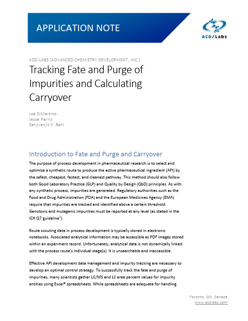
ACD/LABS [ADVANCED CHEMISTRY DEVELOPMENT, INC.]Tracking Fate and Purge ofImpurities and CalculatingCarryoverJoe DiMartinoJesse HarrisSanjivanjit K. BahlIntroduction to Fate and Purge and CarryoverThe purpose of process development in pharmaceutical research is to select and optimize a synthetic route to produce the active pharmaceutical ingredient (API) by the safest, cheapest, fastest, and cleanest pathway. This method should also follow both Good Laboratory Practice (GLP) and Quality by Design (QbD) principles. As with any synthetic process, impurities are generated. Regulatory authorities such as the Food and Drug Administration (FDA) and the European Medicines Agency (EMA) require that impurities are tracked and identified above a certain threshold. Genotoxic and mutagenic impurities must be reported at any level (as stated in the ICH Q7 guideline1).Route scouting data in process development is typically stored in electronic notebooks. Associated analytical information may be accessible as PDF images stored within an experiment record. Unfortunately, analytical data is not dynamically linked with the process route's individual stage(s). It is unsearchable and inaccessible.Effective API development data management and impurity tracking are necessary to develop an optimal control strategy. To successfully track the fate and purge of impurities, many scientists gather LC/MS and LC area percent values for impurity entities using Excel® spreadsheets. While spreadsheets are adequate for handlingand managing numerical data, they are a weak tool for relating chemical structures with the analytical spectra and chromatograms used to identify and characterize them. For example, Excel cannot map chemical routes, search for compounds based on molecular structure, or process analytical data.2Here, we discuss Luminata®—software designed to help project teams map synthetic routes, track impurities, and access analytical data for process development in a systematized and searchable manner. Luminata enables effective inter- and intra-departmental collaboration and automatically calculates carryover values directly from LC/MS and LC data. In this document, we describe two workflows that are often tedious and time-consuming without Luminata—process optimization and carryover calculations.Convenient Management of Process RoutesLuminata facilitates the import of the whole process route associated with a given dataset, including each synthetic stage. The resulting process map enables clear visualization of the impurities at each route phase and a straightforward comparison of molecular composition across reaction steps.Beyond incorporating good manufacturing practice (GMP) into drug substance production, Luminata also allows users to evaluate in-process samples, filtrates, or other entities to assist with synthesis optimization. Figure 1 illustrates an example route optimization of sulfabenzamide, where in-process samples from the reaction, filtrate liquors from product isolation, and the final isolated product are documented.Figure 1. Optimized synthesis of Sulfabenzamide (green, Stage 2) mapped in Luminata. All steps in the reaction are tracked with starting materials (blue), intermediates and products (green), and stage-specific impurities indicated (orange).Sulfabenzamide is an antibacterial substance that is synthesized through a two-step reaction. Within Luminata, this two-step reaction can be documented with all the stages involved. In Stage 1, the process chemist activates the carboxylic acid with carbonyldiimidazole (CDI) to form the imidazolide.3 The chemist then checks how far the activation has progressed toward completion from Stage 1 via a quench conversion to the methyl ester (Figure 1, Stage 1b—Activation). The next substrate is added (Figure 1, Stage 1c), and reaction completion is tested (Figure 1, Stage Reaction Complete). At this point, all known or unknown impurities within the reaction can be separated. Finally, the analyst proceeds through process work-up (Figure 1, Stage 2—Filtrate) and then purification of the compound (Figure 1, Stage 2—Isolated).For all these individual stages, corresponding HPLC data can be associated with each step. Thus, the process map is a powerful tool for comparing stages, denoting the proportion of each impurity rejected at each stage. The software helps conveniently record and share information about the removal and carryover of impuritiesthroughout the process.Each set of reactions also forms an interactive record. Within a record, analysts can examine the impacts of different conditions, such as temperature or solvents, on process optimization. For example, the analyst can assess whether altering a given reaction will generate more impurities at any/each stage. Most process chemists currently use an electronic notebook (ELN) to store this chemical and analytical information, where a massive amount of valuable data is hidden in largely unsearchable PDF documents.Calculating CarryoverIn addition to storing development information in one place, Luminata can link chemical information about impurity fate with all the relevant analytical data. This enables dynamic calculation of carryover. Once the connection of impurities between each stage has been defined by the user (by creating arrows to indicate a conversion or carryover), the corresponding carryover value is automatically calculated from the associated LC/MS data, as illustrated in Figure 2.Figure 2. Creating an arrow indicating conversion of an impurity in the Luminata process map leads to automatic population of the corresponding detection limit (DL) and quantitation limit (QL) in the impurity carryover table.In addition to calculating the carryover at each stage, Luminata also automatically calculates the cumulative carryover value for the entire reaction (Figure 3).Figure 3. As the reaction pathway is defined in the Process Map in Luminata, the Carryover of Impurities Table populates dynamically where ‘DL’ and ‘QL’ represent detection limit and quantitation limit respectively.Carryover is calculated using ‘Area %’ values for two consecutive stages:Carryover=(Area%stage(x)Area%stage(x−1)) x 100%Cumulative carryover is calculated using the carryover calculated for each individual step in the route, for example:Cumulative Carryover=(Carryover stage1→2100)(Carryover stage2→3100)(Carryover stage3→4100) x 100Detection and quantitation limits (DL and QL, respectively) can be edited at each stage. The software relies on user-defined DL and QL values to calculate carryover. Values falling below these limits are denoted with a ‘<’ to indicate the imprecise nature of the calculated result—a practice widely used in industry.4In addition to calculating cumulative carryover amounts for the fates of each impurity, the software enables the comparison of different batches within a complete record set. One use for this functionality is “spike and purge” experiments, where an impurity is spiked into test batches in varying amounts (i.e., 1%, 2%, 3%, 4%, or 5%) to determine if it is purged at the same final stage. Luminata allows users to compare all these different spiked records and create one cumulative carryover table (Figure 4).Figure 4. Cumulative carryover table of two records with differing spiked impurityamounts in Luminata.Carryover calculations for other impurities within the same record can also be determined by selecting the impurity of interest (Figure 5).Figure 5. Selection of an impurity in Luminata allows the carryover value to be calculated automatically from the associated LC/MS data in the Carryover of Impurities table.ConclusionLuminata supports effective workflow optimization for process chemists. This enables informed decision-making by automatically calculating quantitative carryover values for process-related impurities using associated analytical data.References1.ICH, Q7 Good Manufacturing Practice Guide for Active PharmaceuticalIngredients (2016). Link2.Moser, A., Waked, A.E., DiMartino, J. (2021). Consolidating and ManagingData for Drug Development within a Pharmaceutical Laboratory: Comparingthe Mapping and Reporting Tools from Software Applications. OPRD, 25(10),2177-2187. Link3.Montalbetti, C.A.G.N.; Falque, V. (2005). Amide bond formation andpeptide coupling.Tetrahedron, 61, 10827- 10852. Link4.Armbruster, D.A.; Pry, T. (2008). Limit of Blank, Limit of Detection andLimit of Quantitation.Clin. Biochem. Rev., 29(Suppl 1), S49–S52. Link。
流式细胞术基础知识

讲者:***
目录
1、流式细胞术基本定义 2、流式细胞仪介绍 3、荧光染料介绍 4、不同型号流式细胞仪简介 5、流式细胞仪应用
流式细胞术定义
流式细胞术(Flow Cytometry, 简称FCM)是一种可以快速、 准确、客观,并且同时检测单个微粒(通常是细胞)的多 项特性(多参数)的技术,同时可以对特定群体加以分选
淋巴细胞亚群分析可以了解机体在不同条件下的免疫功能 状态,主要包括细胞免疫功能和体液免疫功能。在临床上,主要用 于对免疫系统造成明显干扰的相关疾病的辅助诊断,分析疾病的发 病机理,监控疾病的病程进展,观测疗效及监测预后等等。
流式细胞仪临床应用
临床意义 CD3+ CD3+ CD4+ CD3+ CD8+ CD4+ / CD8+ B细胞 NK细胞
FITC, PE,ECD,PC5 or PECy5.5,PE-Cy7
APC, APC-Cy7
国食药监械(进)字 2014第2403463号
FITC, PE,ECD,PC5 or PC5.5,PC7
红光:638nm 紫光:405nm
APC,APC-Cy5 or APCAlexa Fluor 700, APC-Cy7 or APCAlexa Fluor
谢谢!
部分演示内容来源于网络,如有侵权,请联系删除!谢谢!
APC, APC-Cy7
浙械注准 20192220121
流式细胞仪应用
临床研究
血液,肿瘤, 药理,免疫…
环境研究
湖泊,海洋 生态研究…
生物学研究
遗传,生殖, 微生物,细胞 生物,毒理, 分子生物…
食品制药工业
食品检测、药物筛 选,疫苗研究…
死亡金属乐队综述

死亡金属乐队综述死亡是一种感觉与语言无关.死亡金属从一开始就处于地下状态,所以有很多人都不太了解这种风格。
有的人买了几张死亡风格的专集但不知道该如何区分。
这篇文章会介绍一些比较常见的乐队的风格!现在各大极端网站和论坛都有很多对死亡金属风格详细介绍的很专业的文章,但这些文章对那些没听过或者很少听死亡的朋友起不到什么太大的作用,反倒是让听了很久死亡的人收获不小。
我想了很久,决定以乐队的形式来介绍风格,这样那些初听死金的朋友即使买到一张自己不了解的专集,在这里一看就可以知道这些属于那一类。
还有我在每个乐队名字后面写的第一句话是他们的风格,方便大家查阅,但是有很多乐队在不同时期都有不同的转变,所以我只写他们最具代表性的风格,在后面再说他们的转变!而且有些乐队我看到在被人描述风格时,前面总是加上很多的名词,我感觉没有必要,应为每个乐队都有自己的特点,要是加的话,每个乐队都有自己的风格。
注:括号里是乐队译名!!!DEATH(死亡)-[传统死亡金属]DEATH是的第一张传记被喻为是死亡金属的开端,他早期的专集可以代表当时由敲击过度到死亡的那种最传统死亡金属。
后期的DEATH转变很大技术上有了无限的飞跃,后期DEATH不能在单单看成是一只死亡乐队,他的音乐里包含了很多新鲜的极端理念!MORBID ANGEL(病态天使)-[传统死亡金属]这是一只死亡金属界的大牌乐队,专集屡上各大音乐排行榜,但音乐决不商业,乐队早期和现在的转变不大,只是没有早期敲击味那么浓了。
还有值得一提的是乐队的音乐非常黑暗隐晦,对早期黑暗金属的影响也是有的!DEICIDE(杀神者)-[传统死亡金属]依然是一只坚持到底的乐队,后期音乐上更加残暴一些。
乐队一直以来以反基督题材作为自己的歌词,从始至终!OBITUARY(讣告)-[传统死亡金属]被很多人喻为慢死亡,他们的音乐以中速为主,拥有一个全世界独一无二的主唱,乐队风格没有什么太大的转变!SIX FEET UNDER(六英尺下)-[传统死亡金属]死亡金属超级明星组合,CANNIBAL CORPSE的主唱,OBITUARY的吉他,鼓和被司忘记了,风格也是中速慢速为主,和OBITUARY有相象之处!SINISTER-[传统死亡金属]我曾见过有评论说他们属于残忍死亡金属,我认为他们应该属于传统死,后期换了女主唱音乐是变的极端了一些,但还是没有脱离传统的东西!CARCASS(尸体)-[传统死亡金属]早期碾核音乐的鼻祖之一,91年的专集《NECROTICISM-DESCANTING THE INSALUBRIOUS》开始玩开传统死亡金属,并且作的非常成功,《HEARTWORK》开始在传统死的基础上加入了非常旋律化的东西,对后来的新式旋律死和新激流金属都有很大的影响,后期的《SWANSONG》更是开创了死亡摇滚这一风格。
金属乐发展史
金属乐发展史
金属乐是一种以重金属音乐为主的音乐类型,其源自于20世纪60年代的英国。
最初,金属乐是一种融合了摇滚、蓝调和爵士音乐元素的音乐类型,其音乐风格具有硬朗、沉重、快速的特点。
这种音乐类型的最初创始人是黑色萨巴斯乐队和深紫乐队。
在70年代初,金属乐迅速发展,并形成了一些标志性的乐队和音乐家,例如:末日乐队、铁娘子乐队、莫扎特、矿工乐队等。
在这个时期,金属乐的特点更加突出,包括更大的音量、更快的节奏、更加激烈的吉他演奏、更加丰富的乐器编曲。
进入80年代,金属乐得到了更大范围的认可,这个时期的重要金属乐乐队包括:金属乐队、炼狱乐队、瘟疫乐队等等。
在这个时期,金属乐的音乐元素也得到了更大的创新,从经典的金属乐开始,到更加摇滚、流行和死亡金属等更加细分的音乐类型。
到了90年代,金属乐进入了一个新的时代,这个时期也被称为“黑色高峰”,音乐风格更加黑暗、沉重、快速,代表乐队包括:恶灵降临、黑人世界、死亡乐队等等。
21世纪初,金属乐得到了更广泛的发展,包括更加多元化的音乐元素和风格,例如:后金属、金属核、金属电子等等。
一些新的乐队和音乐家也开始出现,例如:迈克尔·安吉洛、红色雄鹰等等。
总之,金属乐的发展经历了多个阶段,随着时间的推移,这种音乐类型的旗帜已经在世界范围内飘扬。
它不仅代表着一种音乐风
格,更代表着一种精神和态度,即对深邃、探索和创新的追求。
二元铝合金中沉淀初始阶段形核驱动力的简化模型
二元铝合金中沉淀初始阶段形核驱动力的简化模型下载提示:该文档是本店铺精心编制而成的,希望大家下载后,能够帮助大家解决实际问题。
文档下载后可定制修改,请根据实际需要进行调整和使用,谢谢!本店铺为大家提供各种类型的实用资料,如教育随笔、日记赏析、句子摘抄、古诗大全、经典美文、话题作文、工作总结、词语解析、文案摘录、其他资料等等,想了解不同资料格式和写法,敬请关注!Download tips: This document is carefully compiled by this editor. I hope that after you download it, it can help you solve practical problems. The document can be customized and modified after downloading, please adjust and use it according to actual needs, thank you! In addition, this shop provides you with various types of practical materials, such as educational essays, diary appreciation, sentence excerpts, ancient poems, classic articles, topic composition, work summary, word parsing, copy excerpts, other materials and so on, want to know different data formats and writing methods, please pay attention!在研究二元铝合金中沉淀物的形核驱动力时,需要建立一个简化模型来更好地理解其内在机理。
钢炼的英文介绍的课件
02
The theme and meaning of steelmaking
CHAPTER
Topic 1: The Relationship between Human and Machinery
Summary
This topic explores the relationship between humans and machinery in the context of steel refining
Rich color application
Steel refining artists use a variety of colors to create rich and diverse visual effects They often use black, gray, blue, and other colors as the main color, and then add other colors to create contrast and harmony
Steel refining also plays a critical role in recycling used steel and remanufacturing it into new products, which reduces waste and promotes sustainability
The history of steel production dates back to ambient times, evolving from simple craft to industrialized production
Steel refining, or the process of converting raw materials into high quality steel, is a critical step in the production process
Session I Kalio 3rd Metallization Workshop
10
19
10
18
10
17
10
16
10
15
0,0
0,2
0,4 Depth z (µm)
0,6
0,8
© Fraunhofer ISE
5
Seed + Plate Metallization
Aerosol jet printing
Sheathgas
Silver electro plating
Metal Aerosol
SiNx
p
350 300
Resistance [
SEM imaging
250 200 150 100 50
=> RSH
2xRc
1 2 3 4 5 6 7 8 9 10 11 12 13 14 15
Contact distance [mm]
© Fraunhofer ISE
4
Boron Emitters Under Test
© Fraunhofer ISE
12Biblioteka Low Doping Concentration
100
Specific Contact Resistance [mcm²]
90 80 70 60 50 40 30 20 10 0 730 760 790
SiNx/AlOx ARC Stack DeepLow DeepHigh
*Schroder Solar Cell Contact Resistance A review **SZE Physics of Semiconductor devices
© Fraunhofer ISE
13
Solar Cell Results
- 1、下载文档前请自行甄别文档内容的完整性,平台不提供额外的编辑、内容补充、找答案等附加服务。
- 2、"仅部分预览"的文档,不可在线预览部分如存在完整性等问题,可反馈申请退款(可完整预览的文档不适用该条件!)。
- 3、如文档侵犯您的权益,请联系客服反馈,我们会尽快为您处理(人工客服工作时间:9:00-18:30)。
Structural and Electrical Characterization of Locally Screen-Printed Aluminum Contact PointsKarola Rühle, Robert Woehl, Michael Rauer, Christian Schmiga, Daniel Biro Fraunhofer Institute for Solar Energy Systems ISE3rd Metallization Workshop Charleroi, 25-26th October 2011© Fraunhofer ISESi Solar Cells with Passivated and Point-contacted Rear MotivationImprovement of industrial solar cells (e.g. PERC) Local Aluminum back surface fields (Al-p+ BSFs) Alloying process explained by Huster [1] Structural investigations of local BSFs Thickness of Al-p+ region increases for small screen-printed structures [2] Influence of the Al paste amount on the contact depth [3]p-type Si Ag front contactsn+ emitter passivationAl-p+ back surface fieldsAl rear contactAl-p+ region passivation Al rear contact[1] Huster, F et al., 20th EUPVSEC, 2005, Barcelona, Spain [2] Krause, J. et al., 25th European Photovoltaic Solar Energy Conference, 2010, Valenica, Spain [3] Urrejola, E. et al., Journal of applied physics 107 (2010), 124516© Fraunhofer ISESi Solar Cells with Passivated and Point-contacted Rear MotivationImprovement of industrial solar cells (e.g. PERC) Local Aluminum back surface fields (Al-p+ BSFs) Alloying process explained by Huster [1] Structural investigations of local BSFs Thickness of Al-p+ region increases for small screen-printed structures [2] Influence of the Al paste amount on the contact depth [3] Electrical properties of contacts needed: Surface recombination velocity (SRV) of the metalized area Smet[1] Huster, F et al., 20th EUPVSEC, 2005, Barcelona, Spain [2] Krause, J. et al., 25th European Photovoltaic Solar Energy Conference, 2010, Valenica, Spain [3] Urrejola, E. et al., Journal of applied physics 107 (2010), 124516Ag front contactsn+ emitter p-type Si passivationAl-p+ back surface fieldsAl rear contactSmetSpass© Fraunhofer ISELocal Contacts on passivated Si Surfaces Sample StructureApproach:Determination of Smet for different contact point structures Influence of the Al amount on the formation of the Al-p+ and SmetSample cross section:n+ diffusionp-type SiSiO2/SiNx passivation layer Contact point openingsAl-p+Al paste and eutectic© Fraunhofer ISELocal Contacts on passivated Si Surfaces Sample Layout3 Contact point openings rcontact :rcontact:583 µm327.5 µm50 µmrcontact passivation© Fraunhofer ISELocal Contacts on passivated Si Surfaces Sample Layout3 Contact point openings rcontact :rcontact:583 µm327.5 µm50 µm3 Al paste overlaps oAl :oAl passivationrcontact© Fraunhofer ISELocal Contacts on passivated Si Surfaces Sample Layout3 Contact point openings rcontact :rcontact:583 µm327.5 µm50 µm3 Al paste overlaps oAl :© Fraunhofer ISELocal Contacts on passivated Si Surfaces Sample Layout3 Contact point openings rcontact :rcontact:583 µm327.5 µm50 µm3 Al paste overlaps oAl :oAl:∞75 µm25 µm© Fraunhofer ISELocal Contacts on passivated Si Surfaces Sample Layout3 Contact point openings rcontact :rcontact:583 µm327.5 µm50 µm3 Al paste overlaps oAl :oAl:∞75 µm25 µmDifferent paste amounts: 6 mg/cm2, 10 mg/cm2 Different pitches© Fraunhofer ISELocal Contacts on passivated Si Surfaces Determination of SmetPoint structure with Wafer thickness W Pitch Lp Contact radius rcontact Contact area fraction f = π • rcontact 2 / Lp2 Effective SRV Seff Smet, Spass Smet can not be measured directly Model [4] exists to determine Seff (Smet, Spass, material constants) by measurement of τeff (e.g. QSSPC) [5] Boundary condition: Smet >> Spass© Fraunhofer ISEBack side with point contactsSmetSpassLpWrcontact[4] Fischer B., Loss Analysis of Crystalline Silicon Solar Cells using Photoconductance and Quantum Efficiency Measurements, 2003, Cuvillier [5] Sproul A.B., Journal of Applied Physics, 1994Al pastecontact depthAl-p+thicknesseutecticthickness3 ±1 5 ±18 ±3depth77 ±356 ±220 ±5Increasing increasesp+region decreasesFraunhofer Institute for Solar Energy Systems ISE。