T2550
TPS2551DBVR;TPS2550DBVT;TPS2550DRVT;TPS2551DRVT;TPS2550DBVR;中文规格书,Datasheet资料

PRODUCTION DATA information is current as of publication date. Products conform to specifications per the terms of the Texas Instruments standard warranty. Production processing does not necessarily include testing of all parameters.
2
Please be aware that an important notice concerning availability, standard warranty, and use in critical applications of Texas Instruments semiconductor products and disclaimers thereto appears at the end of this data sheet. PowerPAD is a trademark of Texas Instruments.
5 V USB INPUT RFAULT 100 kW FAULT Signal Control Signal FAULT EN ILIM GND PowerPAD RILIM 15 kW 0.1 mF IN OUT 120 mF * TPS2550/51 USB Data USB Port
• • • • • • •
o//:ptth
TPS2550 TPS2551
SLVS736B – FEBRUARY 2008 – REVISED NOVEMBER 2008 ........................................................................................................................................
T2550单元控制器

• PID 回路控制
128 x 64 单色屏 • Elin 100 Mbps连接
128 x 64 单色屏 • 串行口连接 (RS485)
• 处方、顺序功能图、梯形图
• 设定点编程器
操作员终端 - 5.5吋 320 x 240 QVGA
基本组件
• 触摸屏
• 6 个可自定义旳功能键
• 采用单一旳组态环境
– 相同旳组态,支持顾客任务分 配
• 多语言支持
– 针对 I/O 模件 – 针相应用策略
• 全集成旳操作员站
• 符合IEC61131
– 但同步保持运营特有功能 – 一致性、可导出旳位号应用
• 在线组态 • 分离旳I/O组态
T2550 机架单元
• 16 个I/O插槽旳机架
– 支持附加旳冗余备用处理器模件
» 用于存储顾客策略(控制数据库) » 用于 Firmware(固件)存储
– 新增旳 LED状态指示和运营模式切换开关 – 主/备处理器模件间用于冗余热备旳内部通讯
总线,采用自有协议,预防非法访问. – 数据库保护-保护顾客知识产权
T2550 端子模件
• 双模件宽度
– 支持冗余热备及单重化应用 – 在单重化应用时,提供处理器模件“空盒”覆盖空槽
• 符合 IEC 61131 旳组态方式 – 梯形图 – 图形化功能块 – 顺序功能图 – 构造化文本文字
• 外来产品旳集成
采用模块化I/O模件旳分散 控制单元
操作员终端 - 128 x 64 单色屏
基本组件
• 4 顾客自定义功能键
• 易用旳操作导航控制
• 易用旳键盘
– 电话按键风格
• 自定义旳操作员画面
TSL2550中文资料

D Converts Light Intensity to Digital Signal D Infrared Compensation to ApproximateHuman Eye ResponseD Companding A/D for Wide Dynamic Range D Rejects 50 Hz/60 Hz Lighting Ripple D Two-Wire SMBus Serial InterfaceD Single Supply Operation (2.7 V to 5.5 V)D Low Active Power (1 mW typ)D Power Down ModeDLow-Profile Surface-Mount PackageDescriptionThe TSL2550 is a digital light sensor with a two-wire, SMBus serial interface. It combines two photodiodes and a companding analog-to-digital converter (ADC) on a single CMOS integrated circuit to provide light measurements over an effective 12-bit dynamic range.The TSL2550 is designed for use with broad wavelength light sources. One of the photodiodes (Channel 0) is sensitive to visible and infrared light, while the second photodiode (Channel 1) is sensitive primarily to infrared light. An integrating ADC converts the photodiode currents to Channel 0 and Channel 1 digital outputs. Channel 1 digital output is used to compensate for the effect of the infrared component of ambient light on Channel 0digital output. The ADC digital outputs of the two channels are used to obtain a value that approximates the human eye response in the commonly used unit of Lux.This device is intended primarily for use in applications in which measurement of ambient light is used to control display backlighting such as laptop computers, PDAs, camcorders, and GPS systems. Other applications include contrast control in LED signs and displays, camera exposure control, lighting controls, etc. The integrating conversion technique used by the TSL2550 effectively eliminates the effect of flicker from AC-powered lamps, increasing the stability of the measurement.8 SMBData 7 NC 6 NC 5 SMBCLKPACKAGE D 8-LEAD SOIC (TOP VIEW)V DD 1NC 2NC 3GND 4Terminal FunctionsAvailable OptionsAbsolute Maximum Ratings over operating free-air temperature range (unless otherwise noted)†. . . . . . . . . . . . . . . . . . . . . . . . . . . . . . . . . . . . . . . . . . . . . . . . . . . . . . . . . . . . .Supply voltage, V DD (see Note 1) 6 V Digital output voltage range, V O–0.3 V to +6 V. . . . . . . . . . . . . . . . . . . . . . . . . . . . . . . . . . . . . . . . . . . . . . . . . . . .. . . . . . . . . . . . . . . . . . . . . . . . . . . . . . . . . . . . . . . . . . . . . . . . . . . . . . . . . . . . . . . . .Digital output current, I O±10 mA. . . . . . . . . . . . . . . . . . . . . . . . . . . . . . . . . . . . . . . . . . . . . . .SMBus input/output current, I(SMBIN)–1 mA to 20 mA. . . . . . . . . . . . . . . . . . . . . . . . . . . . . . . . . . . . . . . . . . . .Operating free-air temperature range, T A –25°C to 85°C. . . . . . . . . . . . . . . . . . . . . . . . . . . . . . . . . . . . . . . . . . . . . . . . . . . .Storage temperature range, T stg –25°C to 85°C. . . . . . . . . . . . . . . . . . . . . . . . . . . . . . . . . . . . . . . . . . . . . . . . . . . . . . . .ESD tolerance, human body model 2000 V †Stresses beyond those listed under “absolute maximum ratings” may cause permanent damage to the device. These are stress ratings only, and functional operation of the device at these or any other conditions beyond those indicated under “recommended operating conditions” is not implied. Exposure to absolute-maximum-rated conditions for extended periods may affect device reliability.NOTE 1:All voltages are with respect to GND.Recommended Operating ConditionsElectrical Characteristics over recommended operating free-air temperature range (unless otherwise noted)Operating Characteristics, V DD = 3.3 V, T A = 255C (unless otherwise noted) (see Notes 2, 3, 4)and infrared 940 nm LEDs are used for final product testing for compatibility with high volume production.3.The 640 nm irradiance E e is supplied by an Al I nGaP light-emitting diode with the following characteristics: peak wavelengthλp = 640 nm and spectral halfwidth ∆λ½ = 17 nm.4.The 940 nm irradiance E e is supplied by a GaAs light-emitting diode with the following characteristics: peak wavelengthλp = 940 nm and spectral halfwidth ∆λ½ = 40 nm.5.The sensor Lux is calculated using the empirical formula shown on p. 12 of this data sheet based on measured Ch0 and Ch1 ADCcount values for the light source specified. Actual Lux is obtained with a commercial luxmeter. The range of the (sensor Lux) / (actual Lux) ratio is estimated based on the variation of the 640 nm and 940 nm optical parameters. Devices are not 100% tested with fluorescent or incandescent light sources.AC Electrical Characteristics, V= 3.3 V, T = 255C (unless otherwise noted)PARAMETER MEASUREMENT INFORMATIONSMBDATASMBCLKStartConditionStop ConditionPSMBDATAt SMBCLKPSSFigure 1. SMBus Timing DiagramsStart byFrame 1 SMBus Slave Address Byte Frame 2 Command ByteACK by Stop by ACK by Figure 2. SMBus Timing Diagram for Send Byte FormatStart by MasterFrame 1 SMBus Slave Address Byte Frame 2 Data Byte From TSL2550ACK by Stop by MasterNACK by Figure 3. SMBus Timing Diagram for Receive Byte FormatTYPICAL CHARACTERISTICSSPECTRAL RESPONSIVITYλ – Wavelength – nmFigure 404000.20.40.60.8150060070080090010001100R e l a t i v e R e s p o n s i v i t yFigure 5NORMALIZED ADC OUTPUTvs.SUPPLY VOLTAGEV DD – Supply Voltage – VN o r m a l i z e d A D C O u t p u t2.533.544.555.560.20.40.60.811.21.41.61.8PRINCIPLES OF OPERATIONAnalog-to-Digital ConverterThe TSL2550 contains an integrating analog-to-digital converter (ADC) that integrates a photodiode current.First it integrates channel 0 photodiode current and then it integrates channel 1 photodiode current. At the end of the conversion cycle for each channel (approximately 400 ms), the conversion result is transferred to the appropriate channel 0 or channel 1 ADC register. The transfer is double-buffered to ensure that invalid data is not read during the transfer. After the data is transferred, the TSL2550 automatically begins the next conversion cycle. Approximately 800 ms is required for both Channel 0 and Channel 1 ADC registers to be updated. A VALID bit is used to indicate that data has been written to the ADC register after ADC is enabled.Interface to the ADC and control of other device functions is accomplished using the standard 2-wire System Management Bus (SMBus) interface. Both versions 1.1 and 2.0 of the SMBus are supported.Digital InterfaceThe TSL2550 contains an 8-bit command register that can be written and read via the SMBus. The command register controls the overall operation of the device. There are two read-only registers that contain the latest converted value of each of the two ADC channels. The SMBus slave address is hardwired internally as 0111001 (MSB to LSB, A6 to A0).Both the send byte protocol and the receive byte protocol are implemented in the TSL2550. The send byte protocol allows single bytes of data to be written to the device (see Figure 6). The written byte is called the COMMAND byte. The receive byte protocol allows single bytes of data to be read from the device (see Figure7). The receive data can be either the previously written COMMAND byte or the data from one of the ADCchannels.S = Start Condition P = Stop Condition Shaded = Slave TransmissionFigure 6. Send Byte ProtocolS = Start Condition P = Stop Condition Shaded = Slave TransmissionFigure 7. Receive Byte ProtocolCommand RegisterThe command register contains eight bits as described in Table 1 and defaults to 0 (0x00) at power-up. A command summary appears in Table 2.Table 1. Command Register Data FormatThe command register is used primarily to select which register will be read during a read cycle (RSEL) and to control the power consumption of the device (ADCEN and PON). When ADCEN and PON are high, the device is in the full powered-up state and is fully operational. When ADCEN and PON are low, both the ADC and the internal oscillator are powered down, resulting in minimum power consumption. Both ADCEN and PON should always be asserted and de-asserted together. The remaining bits (B4, B3, and B2) in the command register should always be written 0. For details on using the command register, see the Operation section, below.Table 2. Command SummaryADC RegisterThe TSL2550 contains two ADC registers (channel 0 and channel 1). Each ADC register contains two components to determine the logarithmic ADC count value: CHORD bits and STEP bits. The CHORD bits correspond to the most significant portion of the ADC value and specifies a segment of the piece-wise linear approximation. The STEP bits correspond to the least significant portion of the ADC count value and specifiesa linear value within a segment. CHORD and STEP bits all equal to 0 corresponds to a condition in which thelight level is below the detection limit of the sensor. CHORD and STEP bits all equal to 1 corresponds to an overflow condition.Each of the two ADC value registers contain seven bits as described in T able 3. The specific ADC value register read depends on the last written RSEL field to the command register, as described above and in the Operation section, below.Table 3. ADC Register Data FormatThe MSB of the ADC register (VALID bit B7) is used to indicate that data has been written to the ADC register after the ADC and internal oscillator are activated as described in Command Register section.Bits 6 through 0 contain the 7-bit code representing the ADC count value, which is proportional to a photodetector current. In this code, the ADC count value is represented by a piece-wise linear approximation to a log function. The transfer function is broken into 8 chords of 16 steps each. (This code is very similar to µ-law code used in audio compression — it differs in that it does not have a sign bit and it is not inverted.) T able 4 shows the relationship between the CHORD and STEP bits and the CHORD and STEP numbers and values. These are used to calculate the ADC count value.Table 4. CHORD and STEP Numbers and Values vs Register BitsNOTES: A.CHORD VALUE = INT (16.5 × ((2C) – 1))B.STEP VALUE = 2CThe ADC count value is obtained by adding the CHORD VALUE and the product of the STEP NUMBER and STEP VALUE (which depends on CHORD NUMBER).ADC Count Value+((Chord Value))(Step Size)(Number of Steps)) The ADC count value is as a formula:ADC Count Value+(INT(16.5((2C*1))))(S(2C))where:C is the CHORD NUMBER (0 to 7)S is the STEP NUMBER (0 to 15)as defined in Table 4.OperationAfter applying VDD, the device will initially be in the power down state. To operate the device, issue an SMBus Send Byte protocol with the device address and the appropriate command byte to read ADC channel 0 or ADC channel 1 (see T able 2). T o obtain the conversion result, issue an SMBus Receive Byte protocol with the device address. The data byte received will correspond to the value in the ADC register (0 or 1) specified by the previous command. If a conversion has not been completed since power up (either through V DD or ADCEN/PON), the valid bit will be 0, and the data will not be valid. If there is a valid conversion result available, the valid bit will be set (1), and the remaining 7 bits will represent valid data from the previously selected ADC register. Data may be read repeatedly from the currently selected ADC register, and although it will remain valid, the ADC register will not be updated until a new conversion completes for that channel (800 ms total since there are two serial 400 ms per channel conversion times). Note also that the command register itself may be read, as a check to be sure that the device is communicating properly.To power down the device for reduced power consumption, issue an SMBus Send Byte protocol with the device address followed by 0 to clear the ADCEN and PON bits.APPLICATION INFORMATIONThe TSL2550 is intended for use in ambient light detection applications, such as display backlight control, where adjustments are made to display brightness or contrast based on the brightness of the ambient light, as perceived by the human eye. Conventional silicon detectors respond strongly to infrared light, which the human eye does not see. This can lead to significant error when the infrared content of the ambient light is high, such as with incandescent lighting, due to the difference between the silicon detector response and the brightness perceived by the human eye.This problem is overcome in the TSL2550 through the use of two photodiodes. One of the photodiodes (Channel0) is sensitive to both visible and infrared light, while the second photodiode (Channel 1) is sensitive primarilyto infrared light. An integrating ADC converts the photodiode currents to Channel 0 and Channel 1 digital outputs. Channel 1 digital output is used to compensate for the effect of the infrared component of light on the Channel 0 digital output. The ADC digital outputs from the two channels are used in a formula to obtain a value that approximates the human eye response in the commonly used Illuminance unit of Lux:Light Level(lux)+(Ch0Counts)(0.46)(e(*3.13R))where:R = (Ch1 Counts) / (Ch0 Counts)The formula above was obtained by optical testing with fluorescent and incandescent light sources. The light level calculated from the formula will be slightly higher than the actual light level for sunlight and will be slightly lower than the actual light level for composite fluorescent and incandescent light sources.Table 5 contains a summary of the typical sensor outputs for several common light sources.Table 5. Sensor Output SummaryLight from 50 or 60 Hz sources, and especially fluorescent lighting, has a high harmonic content. Since the TSL2550 integrates the ambient light over an approximately 400 millisecond interval (per channel), this light ripple is typically reduced to less than ¼ LSB.Power Supply DecouplingThe power supply lines must be decoupled with a 0.1 µF capacitor placed as close to the device package as possible. The bypass capacitor should have low effective series resistance (ESR) and effective series inductance (ESI), such as the common ceramic types, which provide a low impedance path to ground at high frequencies to handle transient currents caused by internal logic switching.MECHANICAL DATAPACKAGE DPLASTIC SMALL-OUTLINEDETAIL AA2y 6y 1.8 +NOTES: A.All linear dimensions are in millimeters.B.Package is molded with an electrically nonconductive clear plastic compound having an index of refraction of 1.55.C.Actual product will vary within the mechanical tolerances shown on this specification. Designs for use of this product MUST allowfor the data sheet tolerances.D.This drawing is subject to change without notice.PRODUCTION DATA — information in this document is current at publication date. Products conform to specifications in accordance with the terms of Texas Advanced Optoelectronic Solutions, Inc. standard warranty. Production processing does not necessarily include testing of all parameters.NOTICETexas Advanced Optoelectronic Solutions, Inc. (TAOS) reserves the right to make changes to the products contained in this document to improve performance or for any other purpose, or to discontinue them without notice. Customers are advised to contact TAOS to obtain the latest product information before placing orders or designing TAOS products into systems. TAOS assumes no responsibility for the use of any products or circuits described in this document or customer product design, conveys no license, either expressed or implied, under any patent or other right, and makes no representation that the circuits are free of patent infringement. TAOS further makes no claim as to the suitability of its products for any particular purpose, nor does TAOS assume any liability arising out of the use of any product or circuit, and specifically disclaims any and all liability, including without limitation consequential or incidental damages.TEXAS ADVANCED OPTOELECTRONIC SOLUTIONS, INC. PRODUCTS ARE NOT DESIGNED OR INTENDED FOR USE IN CRITICAL APPLICATIONS IN WHICH THE FAILURE OR MALFUNCTION OF THE TAOS PRODUCT MAY RESULT IN PERSONAL INJURY OR DEATH. USE OF TAOS PRODUCTS IN LIFE SUPPORT SYSTEMS IS EXPRESSLY UNAUTHORIZED AND ANY SUCH USE BY A CUSTOMER IS COMPLETELY AT THE CUSTOMER’S RISK.LUMENOLOGY is a registered trademark, and TAOS, the TAOS logo, and Texas Advanced Optoelectronic Solutions are trademarks of Texas Advanced Optoelectronic Solutions Incorporated.。
金属非金属材料国家标准
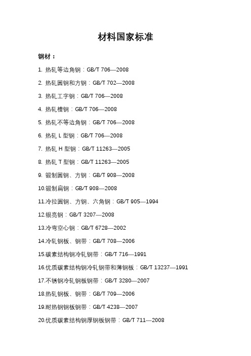
材料国家标准钢材:1. 热轧等边角钢:GB/T 706—20082. 热轧圆钢和方钢:GB/T 702—20083. 热轧工字钢:GB/T 706—20084. 热轧槽钢:GB/T 706—20085. 热轧不等边角钢:GB/T 706—20086. 热轧L型钢:GB/T 706—20087. 热轧H型钢:GB/T 11263—20058. 热轧T型钢:GB/T 11263—20059. 锻制圆钢、方钢:GB/T 908—200810.锻制扁钢:GB/T 908—200811.冷拉圆钢、方钢、六角钢:GB/T 905—199412.银亮钢:GB/T 3207—200813.冷弯空心钢:GB/T 6728—200214.冷轧钢板、钢带:GB/T 708—200615.碳素结构钢冷轧钢带:GB/T 716—199116.优质碳素结构钢冷轧钢带和薄钢板:GB/T 13237—199117.不锈钢冷轧钢板钢带:GB/T 3280—200718.热轧钢板、钢带:GB/T 709—200619.耐热钢钢板钢带:GB/T 4238—200720.优质碳素结构钢厚钢板钢带:GB/T 711—200821.花纹钢板:GB/T 3277—199122.焊接钢管:GB/T 21835—200823.直缝电焊钢管:GB/T 13793—200824.普通无缝钢管:GB/T 17395—200825.低温管道用无缝钢管:GB/T 18984—200326.冷拔无缝异型钢管:GB/T 3094—200027.P3型镀锌金属软管:YB/T 5306—200628.冷拉圆钢丝、方钢丝、六角钢丝:GB/T 342—199729.粉末冶金铁:GB/T 14667.1—199730.烧结金属过滤元件:GB/T 6887—200731.烧结不锈钢过滤元件:GB/T 6886—200732.铸造铜合金:GB/T 1176—198733.压铸铜合金:GB/T 15116—199433.铜以及铜合金线:GB/T 21652—200834.铸造铝合金:GB/T 1173—199535.压铸铝合金:GB/T 15115—200936.铝及铝合金棒材:GB/T 3191—199837.铝及铝合金冷拉冷轧管材:GB/T 4436—199538.铝及铝合金无缝管:GB/T 6893—200039.铝及铝合金板带材:GB/T 3880.1—200640.铝及铝合金花纹板:GB/T 3618—200641.铝及铝合金拉制圆线:GB/T 3195—2008非金属材料:1. 工业用硬聚氯乙烯(PVC-U)管道系统用管材:GB/T 4219.1—20082. 工业用PVC-C管件:GB/T 18998.3—20033. 工业用橡胶板:GB/T 5574—20084. 输水通用橡胶软管:HG/T 2184—20085. 蒸汽橡胶软管:HG/T 3036—19996. 压缩空气用织物增强橡胶软管:GB/T 1186—20077. 氧气橡胶软管:GB/T 2550—20078. 乙炔橡胶软管:GB/T 2550—20079. 耐酸碱橡胶软管:HG/T 2183—199110.聚四氟乙烯棒材:QB/T 3626—199911.耐酸砖:GB/T 8488—200812.平板玻璃:GB11614—200913.钢化玻璃:GB 15763.—200514.硅酸盐水泥:GB 175—200715.掺混合料的水泥:GB/T 175—200716.抗硫酸硅酸盐水泥:GB 748—200517.石棉橡胶板:GB/T 3985—200818.耐油石棉橡胶板:GB/T 539—200819.石棉布、带:JC/T 210—200020.石棉绳:JC/T 222—199421.建筑用砂:GB/T 14684—201122.建筑用卵石、碎石:GB/T 14685—201123.普通烧结砖:GB/T 5101—201124.烧结空心砖:GB 13545—200325.烧结多孔砖:GB 13544—2011。
欧陆新型DCS控制器

T2550自治控制系統(Autonomous Control System)英國歐陸公司新一代的集散控制系統(DCS)T2550是繼T100、T102、T103、T940後的新世代集散控制系統,新系統的名字叫“自治控制系統”(Autonomous Control System),這系统中包含了多個“自治控制器”(Autonomous Controller)互相之間連接到100Mbps 的高速工業以太網(如下圖二所示),其主要特點就是要屏棄傳統的擴展機座層的概念,在這先進的糸統中每一個機座都安裝上一個集合控制和通訊於一身的“自治控制器CPU”,它的主要功能是自行獨立處理從現塲檢測回來的信號、决策並執行控制策略任務,對本身機座上所有I/O 作出快速響應,此外,每台”自治控制器”都支持對等通訊功能,所以它們之間都能互相通訊和協調控制策略,由於這特出的功能,在一個大型的控制系統中,由這些“自治控制器”組成的系統就能發揮前所未見的優點。
假設在這大型的控制系統中有局部的設備或者控制器等發生故障時,整體系統都能繼續工作,通過自治控制系統適當的組態配置,把整個糸統分劃為多個自治控制區,在局部發生故障的時候,系統可立刻自動重組,實現容錯的控制,在云云的DCS系統中,更顯得出類拔粹。
圖一T2550的機座可帶最多128個I/O點,所以對一個1200點的控制系統而言,約需要12個機座,假使用户選用單CPU系統,我們要提供12個CPU,萬一其中一個機座的“自治控制器CPU”有故障,對整個系統而言,影響只限於局部性,但使用傳统的單CPU架構,加上多個擴展機座,萬一這台CPU發生故障,整個系統就要停頓下來,如使用“自治控制系統”,整個系統仍然能保持運行,當然,出現故障的部份,要維修好後才能繼續工作。
此外,我們的系統是支持100%熱備冗余功能,包括CPU、通訊模件、通訊電纜、供電源和I/O模件等,在原有的機座上CPU的右邊,插上另一塊新的CPU模件,便馬上把一個單CPU的機座變成一個熱備冗余的系統,是不需要對原有內部的控制策略作出任何修改,還有,以上的操作可在帶電的情況下在線進行,不需要停止正常運作中的生產過程,由于自治系統有高度的自治功能,我們亦可選擇性地把重要的機座配置成CPU熱備冗余,而其他的機座仍然是單CPU機座,如果要把全部機座都配置成熱備冗余機座是絕對可以的,這樣的配置遠比一般的離散系統的可靠性還要高出很多倍。
天梭图表12.23

T02.1.285.71T02.1.285.61T02.1.285.51T02.1.265.71市场价:2550市场价:2550市场价:2550市场价:2250T02.1.255.71T02.1.215.61T02.1.225.51 T02.1.285.74市场价:2250市场价:2250市场价:2250市场价:3400T02.1.285.54T014.410.11.057.00T014.410.11.047.00T014.410.11.297.00市场价:3400市场价:2850市场价:2850市场价:2850T014.410.11.037.00T014.410.16.057.00T014.410.16.037.00T014.430.11.057.00T014.430.11.037.00T014.430.16.057.00T014.430.16.037.00T005.517.11.047.00市场价:4500市场价:4100市场价:4100市场价:4500T005.517.11.277.00T005.517.11.057.00T17.1.586.32T17.1.586.52市场价:4500市场价:4500市场价:3500市场价:3500T17.1.586.42T17.1.526.52T17.1.516.32T22.1.686.51市场价:3500市场价:3100市场价:3100市场价:3350T22.1.686.31T22.1.686.41T22.1.386.51T22.1.386.31T22.1.386.41T028.410.11.037.00T028.410.11.057.00T028.417.11.037.00市场价:3350市场价:2950市场价:2950市场价:3600T028.417.11.057.00T028.210.11.117.02T028.210.11.057.00T028.210.11.037.00市场价:3600市场价:2700市场价:2700市场价:2700T028.210.22.117.00T028.210.33.117.00T031.410.22.053.00T031.410.22.033.00市场价:3150市场价:3150 市场价:3300市场价:3300T031.410.11.053.00T031.410.11.033.00T031.210.33.053.00T031.210.22.033.00T031.210.11.053.00T031.210.11.033.00T41.1.483.53T41.1.483.33市场价:2700市场价:2700市场价:4350市场价:4350T41.5.413.73T41.1.423.33T41.1.183.53T41.1.183.33市场价:4650市场价:3850市场价:4350市场价:4350T035.407.11.051.00T035.407.11.031.00T038.430.11.057.00T038.430.11.037.00市场价:5150市场价:5150市场价:4650市场价:4650T52.1.481.31T52.1.281.31T52.2.481.13T52.2.281.13T52.2.481.31T52.2.281.31T52.5.481.21T52.5.281.21市场价:2200市场价:2200市场价:2200市场价:2200T97.2.483.51T97.2.483.31T97.5.483.31T97.1.483.51市场价:5100市场价:5100市场价:5500市场价:4500T97.1.483.31T97.1.483.41T97.2.183.51T97.2.183.31市场价:4500市场价:4500市场价:5100市场价:5100T97.1.183.51T97.1.183.31T97.1.183.41T95.1.483.51T95.1.483.31T95.2.483.31T95.2.483.51T95.1.183.51市场价:3100市场价:3500市场价:3500市场价:3100T95.1.183.31T95.2.183.31T95.2.183.51T91.1.486.31市场价:3100市场价:3500市场价:3500市场价:3050T91.1.486.41T91.1.486.51T91.1.426.31T91.1.426.51市场价:3050市场价:3050市场价:2650市场价:2650T91.1.488.31T91.1.428.51T91.1.418.31T050.217.16.052.00T050.217.16.112.00T050.217.36.112.00T033.410.11.013.00T033.410.11.053.00市场价:3500市场价:3800市场价:2100市场价:2100T038.430.11.067.00T007.309.11.116.00T007.309.11.116.00T007.309.11.056.00市场价:4750市场价:4600市场价:4600市场价:4600T009.110.11.057.00T009.110.11.297.00T039.417.11.057.00T039.417.11.047.00市场价:3350市场价:3350市场价:3550市场价:3550T039.417.16.057.00T039.417.16.037.00。
企业会计准则通用分类标准银行业扩展分类标准指南(征求
附件 2:企业会计准则通用分类标准银行业扩展分类标准指南(征求意见稿)为推动企业会计准则通用分类标准(以下简称通用分类标 准)的实施、提升可扩展商业报告语言(XBRL)格式财务报告 的可比性,财政部在通用分类标准的基础上,按照企业会计准则 相关规定和银行财务报告中具有代表性的实务, 扩展制定了通用 分类标准银行业扩展分类标准 (以下简称银行业扩展分类标准), 未来将随企业会计准则和通用分类标准的修订进行修改、 补充和 完善。
银行业扩展分类标准适用于执行企业会计准则并实施通用 分类标准的商业银行和政策性银行。
本指南是银行业扩展分类标准的说明性文件, 旨在帮助具备 一定 XBRL和通用分类标准知识基础的使用者, 了解银行业扩展 分类标准的架构及内容,以便开发本企业扩展分类标准,编制和 报送符合企业会计准则、 通用分类标准和银行业扩展分类标准规 定的 XBRL格式财务报告。
一、银行业扩展分类标准在通用分类标准体系中的定位银行业扩展分类标准是通用分类标准在银行财务报告领域 的行业扩展分类标准, 其整体架构设计不仅考虑了与通用分类标 准的结合, 还考虑了未来我国通用分类标准体系中的其他行业的 财务报告扩展分类标准和监管扩展分类标准, 以及实施单位的扩展工作。
(一)与通用分类标准的关系通用分类标准是符合企业会计准则和 XBRL 技术规范系列 国家标准的 XBRL 格式财务报告标准,是企业编制 XBRL 格式 财务报告的基础。
行业扩展分类标准是通用分类标准在具体行业 财务报告领域的扩展,反映了该行业通行的财务报告实务。
在编 制 XBRL格式财务报告的过程中, 各实施单位需要以通用分类标 准为基础创建企业扩展分类标准, 其中不仅涉及大量对行业共性 实务进行 XBRL 重复建模的工作量,而且降低了这部分 XBRL 数据所反映的财务报告信息的可比性。
银行业扩展分类标准等行 业扩展分类标准填补了这一空白,成为通用分类标准的必要补 充。
T2550_PAC介绍与选型
T 2550MODEL•Cost effective controllerProgrammable Automation Controller (PAC)Specification SheetP l a n t F l o o rVisualisationOperation ViewerStore & ForwardInformation Server Reporting ReportsOperation Server (System Platform)ValveEquipment ModulePhasesConfigurationAt the heart of the system is the LINtools configuration and engineering station. LINtools is a comprehensive set of configuration, test, documentation and commissioning tools for strategy elements distributed over the LIN control backbone. The LINtools suite includes graphical configuration of block structured continuous control, sequence control SFC’s, ladder and graphics for any LIN based product. VIEW and Online reconfiguration modes allow dynamic monitoring and editing of running databases and flow charts.LINtools follows the IEC 61131-3 standard for sequence configuration, while adopting a decoupling of continuous and sequential strategy appropriate to complex process control. LINtools is designed for simplicity and productivity. Online help, free-format text annotation and area editing are included to make LINtools easy to use and configuration easy to understand and reuse. LINtools runs on a standalone or networked PC.IEC 61131Languages appropriate for the I/O type and for the application °Function Block Diagram°Sequence Function Chart°Structured Text°Ladder Logic ControlOnline reconfigurationLarge and complex control systems are expected to serve many needs and work well for long periods without shutdown under ever varying workloads. Online reconfiguration provides a useful foundation for enhancement of a deployed control system and allows modification of the systems application software while it is running. It allows active strategy components to be modified, wrapped with additional functionality or replaced with a different implementation. The T2550 PAC has generic support for adding and hot swapping I/O. Online reconfiguration can use the same or new I/O interfaces and any internally available variables.You can tentatively add and delete function blocks and wires to create a new or improved control strategy for your application –while the process is running. You can then try and untry the strategy to ensure it is correct before final application. A secure file tracking system is provided for version control.Continuous controlContinuous strategies are configured graphically on screen using ‘block structured’ techniques implemented across the system. The control configurator supports a comprehensive library of functions together with powerful editing and compound definition facilities. Merging allows the re-use of similar sections of databases, avoiding duplication of effort. Free text can be placed on the screen or attached to function blocks for simple production of descriptive documentation.Context-sensitive help reduces the need of referring to manuals.SequenceSequences are configured graphically using Sequential Function Charts (SFCs) following the IEC 61131-3 standard. Steps initiate Actions which may be Structured Text statements (ST) or nested SFCs. Transitions determine when control passes from one step to the next. By accessing the continuous control strategy this configurator presents the available points through a menu system – eliminating the need to remember the names of points and reducing the likelihood of typing errors.The sequence configurator supports text annotation and context-sensitive help. A combination of mapping lists and generic Sequential Function Charts are available to easily duplicate identical SFC models on different units (tags).Action blockAction blocks in the continuous control strategy have their functionality defined in Ladder diagrams or Structured Text (ST) within a standard template. These are particularly useful for implementation of plant control modules.Auto I/O configurationThe instrument can automatically create its own LIN Database, including all necessary module and I/O Function Blocks, based on the I/O detected in the Base Unit. When the detection is complete, an operational database is created and runs automatically.Automatic database creation is available from within LINtools when connected to a network containing T2550 PACs. This function allows new I/O to be added to an existing configuration, on line.DocumentationLINtools provides an electronic documentation facility including the graphical representation of the control strategy and a listing of the block parameters and connections. This can be transferred across the network and output can be to a printer, Postscript or AutoCAD compatible format. Free-format user annotations can be added to complete your documentation requirements.Multi-setpoint programmerMany applications need to vary the process value over time. Temperature control is one such application in which it is very common to ‘ramp’ the process value (channel) from one level to another over a set time period using a setpoint program.The PAC provides support for multiple setpoint programs that can be run simultaneously. Each program is capable of profiling up to eight channels, with up to 32 segments per profiled channel. In addition to controlling the setpoint during each segment of the profile, the controllers can also be used to activate up to 16 digital events during a segment.The setpoint program feature enables an operator to select and run a pre-configured setpoint program. A preview facility allows the operator to view the selected program before running it. Once the program is running, the setpoint and achieved processvalues are plotted on the trend screen.Eurotherm Part No. HA029159 Issue 9 December 093PAC Specification SheetData archivingData archiving is used to copy selected parts of the history, i.e.,one or more history files (.uhh) to primary, secondary or tertiary FTP Servers..Historian store and forward‘Store and forward’ is a self healing 21 CFR Part 11 data archiving system which automatically stores data during a communication failure in the T2550 PAC and then forwards this data to theconfigured data historian server once communication is reinstated.The T2550 PAC provides dual redundant data acquisition using Secure.uhh files created at the local level, which results in a secure electronic recording system with total data integrity.Alarm managementAlarms are managed and collected within the T2550 PAC to provide features such as alarm status and priority,acknowledgement, date and time stamping at the source, as well s suppression and local message historian storage.Open communicationsThe PAC provides a special function block to define any simple serial communications protocol. This function block can be used to integrate many 3rd party devices which use ASCIIcommunications, such as bar code readers and particle counters.Direct control over transmit and receive also allows multi-node connections.HMI ReportsHMI Reports provides an intuitive reporting package to develop and print reports using the secure data from the T2550 PAC. The package includes a report studio for configuring report projects and a run-time execution module to generate and print reports in many different formats to printers and file servers, and via e-mail. HMIreports is also optionally available as a web portal.Setpoint program wizardFor ease of use, LINtools incorporates a wizard for creating a setpoint program. By following the on screen prompts and editing the parameters as required, a setpoint program can be simply and quickly created with all required blocks automatically created and added to the database.Setpoint program editorIn addition to the setpoint program wizard, programs can be created or edited off–line using the setpoint program editorsupplied with LINtools. As an ActiveX, this tool can be inserted in any of your visualization packages.Redundant recording and archivingPAC Programmable Automation Controllers have internal non-volatile flash memory for secure tamper resistant data storage,providing for redundant data logging. In addition all PACprocessors support Ethernet connectivity. As such, data stored within the internal flash memory can be configured to periodically archive to primary, secondary and tertiary FTP servers. Archiving files to FTP servers provides a secure, infinite archiving capacity.Data historianData historian is used to store PV’s, message and alarminformation in the internal flash memory in order to generate historical data in the form of a set of secure, tamper resistant history files.The following example provides estimated memory durationbased on an 8-way base logging 16 Parameters to a single group.FTP pushFor efficiency, historical data files are automatically deleted on a first in first out (FIFO) basis from the internal flash memory of the PAC (7Mb for history). In order to ensure longevity of data the PAC is able to push historical data files (.uhh) to primary,secondary or tertiary FTP servers at user defined intervals. Thus,depending on the archive strategy chosen, data is never lost. As an alternative, Eurotherm Review can be used to pull data directly from the T2550 PAC255BF base unitThe base unit is fitted with the T2550 PAC I/O controller modules plus additional I/O modules. These modules plug onto terminal units, which provide the wiring interface between the plant or machine and the I/O modules. Bases are available in 5 sizes to suit the number of modules required in a particular system.Communication between the I/O modules and the processor is effected by the use of a passive internal module I/O bus running the width of the base. Each module position is tracked separately for additional security during live replacement of I/O modules.The base consists of an aluminium extrusion, the internal I/O bus and mounting supports. It is designed to be DIN rail mounted or directly fixed to a bulkhead or mounting plate. Both base and modules can be installed horizontally or vertically.MechanicalI/O Module capacity0 46816Width (mm)36164214264467 Weight no modules (Kg)0.20.450.60.7 1.2all modules (Kg)0.5 1.3 1.7 2.1 3.7 Height:180mmDepth:102.9-132.9mm with retaining lever raised Mounting:DIN rail or Bulkhead, can be mountedhorizontally or verticallyDIN rail:Use symmetrical DIN rail to EN50022-35 x 7.5 or 35 x 15Casing:Without additional protection IP20 Ventilation space:25mm free space above and belowTermination unitsThe I/O modules are mounted on the base using terminalassemblies. Terminal assemblies provide the interface betweenthe input and output signals and the I/O modules. Terminalassemblies and I/O modules are keyed to inhibit insertion ofthe incorrect module to prevent damage to both equipmentand plant.Individual termination units provide for easy modulereplacement leaving the field wiring connected. Modules areinserted and removed from the termination unit using a unique,tool-less, locking lever system.Test disconnect unitsTerminal assemblies have an optional fuse or link (isolator or disconnect). This provides a series of connections between thecustomer terminals and the I/O module, permitting pluggablefuse or link units to be placed in series with the signal. Fuse andlink units are not interchangeable.T2550 PAC - General SpecificationsSupply voltage range:19.2 to 28.8V dcVA requirements: < 80W maximum for fully loaded rackFuse rating: 4A time lag (Not customer replaceable)IOC warm start time:12 hours without external batteriesIOC power consumption: 1.5W maximumSurge current:8A maximumModule pwr consumption:See individual module specification EnvironmentalOperating temperature:0 to 55°CStorage temperature:-25 to 85°CRelative humidity: 5 to 95% (non-condensing)RFIEMC emissions:BS EN61326-1:2006EMC immunity:BS EN61326-1:2006SafetyBS EN61010-1:2001Installation cat II, Pollution degree 2Safety earth and screen connections are madeto clearly marked earth terminals at thebottom of the baseVibrationEN60068-2 test FCVibration:IEC1131-2 section 2.1.30.075mm peak amplitude 10-57Hz;1g, 57-150HzShock:20g static shockDiagnostic LED’sDiagnostic LED’s indicate module diagnostic status.All modules: A green LED at the top indicates the moduleis powered and operating correctlyPAC analogue modules: Have red LEDs for each channel to indicatechannel failurePAC digital modules: Have Yellow LEDs for each channel to indicatethe channel state.Processor module:Primary processor and communications diagnostics are available from the LEDs on the front of the processor module. More advanced diagnostics are available remotely using LINtools monitor online over Ethernet to review the diagnostic blocks.PAC Controller module: A green LED at the top indicates themodule is powered and operating correctly Internal diagnostics: A red LED indicates failure of the internalself diagnostic routinesBattery (if installed): A green LED indicates battery health Serial communications: A yellow LED indicates communications activityORDER CODEPassivebackpaneTerminal Unitfor the T2550PAC8 Module (as shown)1616 Module6 ModuleAny type of I/O module canbe placed at any slot positionTerminal Units click into place to suitthe T2550 PAC I/O module required214mm264mm467mmModule Side View102.9mm180mm4 Module164mmTerminal Unit forT2550 PAC I/O moduleSPECIFICATIONS Mechanical DetailsCPU redundancyProcessor redundancy is available for continuous, logic and sequence control.A pair of processors operate in primary / secondary configuration with a high speed data link between them providing exact tracking of the control,logic and sequence databases. Transfer from the primary to secondary processor is bumpless.The non-active processor can be replaced while the system is running and on synchronisation it loads its strategy from the active primary processor.Redundant:< 0.6s bumpless transfer for processor and I/O Changeover time: dependant on application size Synchronisation time: dependant on application sizeProcessor SwitchoverDuring a processor switch over all outputs remain at the last value. The new primary processor begins executing is application from precisely the same point as the original processor.Each processor has its own Ethernet IP address and each redundant pair uses two neighbouring node addresses on the ELIN network. This enables the system to communicate with the primary while still continuously testing communications to both processors. On processor switch over the ELIN node address is dynamically swapped to allow SCADA applications to display and log uninterrupted data. Changeover amongst LIN nodes is transparent.The following conditions can cause the processor to switch over:Hardware failure:Failure of primary controller internal health checks.Hardware removal: Removing the primary processor will cause the secondary to take immediate control.Removing the secondary will have no effect on control but will cause a system alarm on redundant configured systems.Internal communications:Primary and secondary controllers continually monitor the communications to the I/O on the local base. Should the primary controller not be able to communicate with the I/O and the secondary can still communicate with the I/O changeover will occur.If the secondary processor observes a fault in the primary communications or can see more I/O modules the secondary processor will request a changeover.External communications:Each processor in a redundant pair continuously monitors external controller communications. Should the primary controller not be able to communicate with other declared nodes on the LIN network and the secondary can still communicate with the declared nodes a change over will occur.If the secondary processor observes that it can see more declared nodes,the secondary processor will request a changeover.Manual request:A user can request a changeover if a secondary processor is running, synchronised and healthy.Removable flash memory card:The storage of the cold start application Power supply connectionThe duplex terminal unit supports dual power supply connection. In the event of a single power supply failure both processors are still supplied allowing redundant operation to continue uninterrupted.A super capacitor maintains memory for up to 12 hours in the event of complete power failure to facilitate hot start of the processors. An external battery can be fitted to extend this back up time on the redundant system.Super cap (Processor):Maintains memory/real time clock and enables hot start for up to 12 hours in absence of battery backup inputSimplex (O base):Battery support for data in SRAM and the Real-Time Clock for a minimum of 72 hourcontinuous (5 year intermittent use)Redundant:Additional terminals for an external battery connection to support SRAM and the Real-Time ClockInternal battery type:Lithium Manganese Dioxide PA250983External rechargeable battery:Use S9537 Battery charger:Use S9538Watchdog RelaysEach processor is fitted with a single watchdog relay.Watchdog relay:SPST, 1 per CPU, connectable in parallel or seriesContact rating (resistive):24V ac/dc at 0.5A Isolation:30V ac rms or 60V dcLive plug-inProcessors and I/O modules can be replaced while powered without any disturbance to the field wiring or other inputs and outputs – reducing downtime and minimising disturbance to other signal conditioning strategies.T2550 PAC – ORDER CODEControl specificationsContinuous Database resourcesMaximum database size . . . . . . . . . . . . . . . . . . .default max values 210k bytes Database resourcesNumber of database blocks . . . . . . . . . . . . . . . . . . . . . . . . . . . . . . . . . . . . . .630Number of database templates . . . . . . . . . . . . . . . . . . . . . . . . . . . . . . . . . . . .50Number of template libraries . . . . . . . . . . . . . . . . . . . . . . . . . . . . . . . . . . . . . .32Number of external databases . . . . . . . . . . . . . . . . . . . . . . . . . . . . . . . . . . . . .32Number blocks in local Dbase cached elsewhere . . . . . . . . . . . . . . . . . .1260Number blocks in remote Dbases cached locally . . . . . . . . . . . . . . . . . . . .315Number of server tasks . . . . . . . . . . . . . . . . . . . . . . . . . . . . . . . . . . . . . . . . . . . . .6Number of field-to-field connections . . . . . . . . . . . . . . . . . . . . . . . . . . . . .1260Sequence Control ResourcesSequence memory Programme data . . . . . . . . . . . . . . . . . . . . . . . . .105k bytes SFC ResourcesNumber of root SFCs loadable . . . . . . . . . . . . . . . . . . . . . . . . . . . . . . . . . . . . .31Number of steps loadable . . . . . . . . . . . . . . . . . . . . . . . . . . . . . . . . . . . . . . . .420Number of ‘wires’ permitted going into and out of step . . . . . . . . . . . . .1407Number of transitions . . . . . . . . . . . . . . . . . . . . . . . . . . . . . . . . . . . . . . . . . . . .630Number of ‘wires’ permitted going into transitions . . . . . . . . . . . . . . . . . .840Number of action associations . . . . . . . . . . . . . . . . . . . . . . . . . . . . . . . . . .1680Number of actions . . . . . . . . . . . . . . . . . . . . . . . . . . . . . . . . . . . . . . . . . . . . . .840User TasksMultiple tasks are available to the user to tune the update rate of I/O response and the control function.User Tasks . . . . . . . . . . . . . . . . . . . . . . . . . . . . . . . . . . . . . . . . . . . . . . . . . . . . . . . .4User task update ratesTask I – Synchronous to Fast I/O . . . . . . . . . . . . . . . . . . . . . . .10ms or N*10ms Only version 2 10ms I/O types can be assigned to this task (see table below) .Task 2– Auxiliary task to task1 . . . . . . . . . . . . . . . . . . . . . . . . .10ms or N*10ms Runs at task 1 rate or integer multiple of task 1 rateTask 3– Synchronous to Standard I/O . . . . . . . . . . . . . . . .110ms or N*110ms All analogue and digital I/O types can be assigned to this taskTask 4– Auxiliary task to task3 . . . . . . . . . . . . . . . . . . . . . . .110ms or N*110ms Runs at task 3 rate or integer multiple of task 3 rate Supported I/O Module TypesThe T2550 PAC shares I/O modules with the 2500 I/O.Notes†The T2550 PAC supports only Version 1 modules in simplex operation.*Version 2 Ana Out modules can run at the 10ms task on 4 or 6-way bases. Continuous strategy function blocks categoriesF = Foundation, S = Standard, C = Control, A = AdvancedCommunicationsEthernet communicationsEthernet The PAC supports Ethernet LIN (ELIN) protocol that provides secure peer-to-peer communications between bases and to other Ethernet devices over 10/100baseT Ethernet from each processor. Simultaneously itcan support Modbus-TCP Master or Slave to other Modbus-TCP devices.ELIN portConnectors:Shielded RJ45 connector per processor Network medium:Ethernet Cat5Network type:LIN over EthernetSpeed:10/100baseTNetwork topology:Star connection to a switchLine length (maximum):100 metres, extendible by repeater Allocation of IP address:Fixed, DHCP, Link-Local, BootPBroadcast storm protection:Integrated in the processorLIN address:8-way switch-bank – Duplex (bits SW2-8)10-way switch-bank – SimplexMax numbers of slaves:16 Modbus TCP slavesSerial communicationsThird party devices such as PLCs supporting Modbus can be readily integrated into the ELIN based architecture by direct connection to T2550 PAC control units. The Modbus communications allows a T2550 PAC to be used as a gateway providing access to database elements in any ELIN node.RS422/485 serial communicationsConnector:2x RJ45 connectorComms medium:RS422 (5-wire) or RS485 (3-wire), jumper select Line impedance:120Ω-240Ω twisted pairLine length: 1220m maximum at 9600 bits/secUnits per line:16 maximum (electrical loading) expandableby use of buffersMax number of slaves:64 serial slave devicesNote:Use of a comms buffer/isolator is recommendedModbus/J-BUSProtocol:Modbus/J-BUS RTU configurable master or slave Data rate:Selectable 600-38.4k bits/secData format:8 bit, selectable parity 1/2 stop bitsModbus data tables:64, configurable as registers or bits Maximum table length: 200 registers or 999 bitsRedundancy:Modbus communications are supported bythe PAC in simplex and redundant mode3 GWF may be run simultaneously1x Modbus TCP master1x TCP slave1x Modbus RTU slave or masterMax (GWF) file size: 20k bytesProfibusPhysical medium:2-wire, RS485Connectors:Single 9-way D-typeData rate:Determined by Profibus master, 12MB max. Isolation:50V dc; 30V acOpen communicationProtocol:Device drivenData rate:1200 to 38.4k bits/secData format:7 or 8 data bits, none/even/odd parity,1 or2 stop bitsORDER CODEI/O ModuleFuseDisconnectorsHealth StatusExternal Battery ConnectorSerial Communications Port24V dcand Power (Terminal Unit)I/O Status2500MF-A Two channel analogue inputThis analogue input module is used to monitor analogue signals from a wide range of plant sensors. The mA and TC inputs each require the appropriate terminal unit.The second channel of the AI2 has a special high impedance range for use with zirconia probe inputs.No of channels: 2Input types: TC, RTD, Volts, mA, mV, Potentiometer, Pyrometer, Zirconia probemV range: -150mV to +150mV at input impedance >100MΩmA range: -22mA to +22mA with 5Ω burden in the terminal unitVolts range: -10.2V to +10.2V at input impedance 303kΩ RTD support: Support for 2, 3 and 4 wire resistance thermometer devicesOhms range: 0 to 600Ω 3- or 4-wire lead compensation Hi Ohms range: 0 to 5kΩ 3- or 4-wire lead compensation Pot range: 5% to 95% ‘rotation’ of 100Ω to 5kΩ pot Resolution: Better than 0.001% of range Linearity:Better than 0.003% of range Input filtering: OFF to 999.9 secondsInput accuracy: Electrical input factory calibrated to better than 0.1% of readingSystem isolation: Reinforced, 264V ac maximumChannel isolation: Reinforced, 264V ac maximum between thermocouple channelsFunctional:264V ac maximum between RTD, volts and mA Series mode rejection:60dB (50-60Hz, 1mA rms)Common mode rejection:120dB (50-5kHz, 50V rms)Power consumption: 2W maximumTC Input specification Linearisation types: J, K, L, R, B, N, T, S, C, PL2, PT100, Linear, SqRoot, plus customCJC system:Measured by RTD fitted on terminal unit Initial CJC accuracy: ±0.5°C typical (±1°C maximum)CJC rejection:Better than 30:1 over -10°C to +70°CNote:User calibration options can improve performance, limited only by noise and non-linearity.2500MF-C Three channel analogue inputProvides three isolated current input channels specifically designed to meet the requirements of modern two wire transmitters. Each channel has its own isolated 24V supply for transmitter excitation.Each channel’s 24V dc supply is protected against short circuit and utilises a sophisticated trip and try system in which the module senses over current and cuts the power. After a period the circuit checks for continued circuit malfunction.The module can be optionally fitted with disconnects to allow isolation of an individual input to allow work on the loop to continue safely.No of channels: 3Input range:-28mA to +28mAResolution: Better than 1uA (16 bits with 1.6 sec filter time)Linearity:Better than 10uAInitial accuracy: Factory calibrated to better than ±0.1% of reading Input filtering:OFF to 999.9 secondsBurden resistance: 60Ω nominal, 50mA max currentChannel PSU: 22-25V dc, current limited 30mA nominal, self-resettingSystem isolation: Reinforced, 264V ac maximum Channel isolation: Functional, 50V ac maximum Power consumption:4W maximumNotes:er calibration options can improve performance, limited only by noise and non-linearity.2.Total burden can be increased to 250Ω or HART by cutting a link track on the terminal unit.AI2 – ORDER CODEAI3 – ORDER CODE2500MF-D Four channel analogue inputThis analogue input module is used to monitor analogue signals from a wide range of plant sensors. The mA and TC inputs each require the appropriate Terminal Unit.No of channels: 4Input types: TC, mV, mA, PyrometermV range: -150 - +150mV at input impedance >100MΩ mA range: -22 - +22mA with 5Ω burden in the terminal unit Resolution: Better than 0.001% of range Input filtering:OFF to 999.9 secondsInitial input accuracy: Electrical Input Factory Calibrated to better than 0.1% of readingSystem Isolation: Reinforced, 264V ac maximumChannel isolation: Functional, 264V ac maximum separating Ch1and Ch2 from Ch3 and Ch4Series mode rejection:60dB (50-60Hz, 1mA rms)Common mode rejection:120dB (50-5kHz, 50V rms)Power consumption: 2W maximumTC Input specification Linearisation types: J, K, L, R, B, N, T, S, C, PL2, linear, SqRoot, plus customCJC system:Measured by RTD fitted on terminal unit Initial CJC accuracy: ±0.5°C typical (±1°C maximum)CJC rejection:Better than 30:1 over -10°C to +70°CNotes:er calibration options can improve performance, limited only by noiseand non-linearity.2.Wiring care and sensor choice should be used to prevent ground loops when using non-isolated TC’s.2500MF-E Two channel analogue outputThis analogue output module provides two isolated analogue output channels. Each output can be independently configured for current or voltage mode.The module can be optionally fitted with disconnects to allow isolation of an individual output to allow work on the individual loop to continue safely.No of channels: 2Current output: -0.1 to 20.5mA; 10V dc max. compliance with total burden less than 500ΩVoltage output:0 to 10V dc; 20mA max. compliance with total load greater than 500ohms-0.5 to 10.5 V dc; 8mA max. compliance with total load greater than 1500ΩResolution:Better than 1 part in 10,000 (15 bit typical)System isolation: Reinforced, 264V acChannel isolation: Functional, 264V ac maximum Power consumption:2.2W maximumAI4 – ORDER CODEAO2 – ORDER CODE。
TBT2560 TBT2702铁道客车用非金属材料的选择要求
TB/T2560 TB/T2702铁道客车用非金属材料的选择要求TB/T2560:1995 铁道客车用非金属材料的选择要求。
本标准等效采用了法国标准NFF16-101:1988TB/T2702:1995 铁道客车电器设备非金属材料的阻燃要求。
本标准等效采用了法国标准NFF16-102:1988TB/T2560标准等级划分材料对火反应等级可分为:M0-M4,共5个等级;I0-I4级,共5个等级;A-D级材料发烟的等级可分为:F0-F5级材料对火反应等级可分为:M0-M4,共5个等级;I0-I4级,共5个等级;A-D级,共4个等级。
根据TB/T 2639.5:1995的规定进行测试,将材料分为M0-M4 五个等级。
根据TB/T 2701:1996或TB/T 2919:1998的规定,作氧指数(I.O.)等级测试;根据GB/T 5169。
12:1999的规定,作灼热丝试验,根据这两者测试结果,将材料分I0-I4五个等级。
导线和电缆根据TB/T 2836:1997标准进行A-D四个等级测试。
材料烟雾毒性等级可分为:F0-F5级根据GB/T 8323:1987 (烟密度测试)及TB/T 2946:1999(毒性测试)这两个测试结果,评定材料烟雾毒性等级F0-F5。
TB/T 2560 及TB/T 2702参考标准:NF F 16-101: Railway rolling stock fire behaviour choice of materialsNF F 16-101: 所有车辆---燃烧行为---材料选择NF F 16-102: Railway rolling stock fire behaviour choice of materials-Electrical Equipment NF F 16-102: 所有车辆---燃烧行为---材料选择---在电力装备上的应用更多TB/T 2560 ,TB/T 2702等其它铁道客车防火阻燃测试,请联系中国防火网以上内容由南京睿督公司(咨询电话:025-8658 3475)提供,转载请注明出处。
25t汽车起重机参数(XCT25L5)
副起升机构
(m/min)
135
起重臂伸缩时间
*
全伸
(s)
95
全缩
(s)
100
变幅时间
*
全程起臂
(s)
35
全程落臂
(s)
-
支腿收放--水平
*
同时放
(s)
25
同时收
20
支腿收放--垂直
*
同时放
(s)
25
同时收
(s)
20
如有侵权请联系告知删除,感谢你们的配合!
(m)
27
最大爬坡能力
(%)
45
最小离地间隙
(mm)
260
接近角
(°)
12
离去角
(°)
14
制动距离
(m)
≤10(车速为30km/h)
百公里油耗
(L)
30
主要性能参数
*
最大额定总起重量
(t)
25
最小额定幅度
(m)
3
基本臂最大起重力矩
(kN·m)
1132
转台尾部回转半径
(mm)
3340
支腿
*
纵向
(m)
5.65
动力参数
*
发动机型号
-
SC9DF290.1Q4/SC9DF290.2Q4
发动机额定功率
(kw/(r/min))
213/1900
发动机最大扭矩
(N.m/(r/min))
1400/1400
行驶参数
*
行驶
*
最高行驶速度
(km/h)
90
最低稳定行驶速度
(km/h)