热字1004-1007 欧洲贵族-操作说明
欧洲汽车DE型号高压气席高流量舒张器操作手册说明书

SERVICE MANUALF105/200-6031-0/0702/AMA40L HIGH FLOW INSUFFLATORThis manual contains information that is subject to copyright. All rights reserved. This manual should not be photocopied, duplicated on microfilm or otherwise copied or distributed, completely or in part, without the approval of the manufacturer.Some of the parts and equipment referred to in this manual bear registered trademarks but are not identified as such. It should therefore not be assumed that the absence of the trademark indicates that any given designation is not subject to trademark protection. Also, it is not evident whether patents or copyrights exist.Users of ours products should not hesitate to point out to us any errors or unclarities in this manual.Copyright © STRYKER ENDOSCOPYManufacturerSTRYKER ENDOSCOPY5900 Optical CourtSan Jose, CA 95138USATel: +1 800 624 4422Fax: +1 800 729 2917US-2US-3US-4US-5US-6US-7US-82-3-1: Position of High Pressure Unit HPUTurn adjustment screw 1at high-pressure controllerincrease pressure until triggering of the high-pressure valve 3can be clearly heard (hissing sound). Reverse screw 1 until you can no longer hear any hissing sound. The then reached pressure has to be above 4 bar.Reset the adjustment screw to the marked position. AdjustmentUse the adjustment screw 3 of the high-pressure valvefor any adjustments.High Pressure Regulator HPRNOTEThe output value drops with rising temperaturelong operating hours).Relieve pressure of tube at magnetic valve (briefly remove and reconnect tube) until a stable final value of 3.2 bar isreached (±0.6).Remove manometer and reconnect tube.US-9Fig. 2-4-1: F105 Low Pressure Controller Settings2-5Low Pressure Safety Valve LSVClose device exit using a tube clamp (Fig. 2-6-1 , 4).In the service menu, open the LSV Adjust menu option and check the settings.AdjustmentUse the adjustment screw of the low-pressure safety valve for a slight adjustments.2-6Testing Low Pressure Unit for LeaksUS-102Function Test2-8Testing Overpressure Alarm1.Attach a tube and an air-filled syringe to insufflation tubeconnection (Fig. 2-5-1).e the syringe to slowly generate a pressure of 15 mm Hg.3.Slowly increase pressure to 21 mm Hg and press the Start/Stop key.4.An alarm is sounded after approx. 5 seconds andOverpressure is displayed.5.Select gas flow level 2.6.The bleeder (relief) system is activated after approx. 5seconds (time and pressure value can be changed in theuser menu).7.The bleeder system relieves the pressure; alarm andOverpressure warning symbol are turned off.8.Press the Start/Stop key and remove test tools andresources.AdjustmentReplace low-pressure unit.2-9Testing Blockage Alarm1.Connect insufflation tube and close off the end of the tube.2.Press the Start/Stop key.3.An alarm is sounded after approx. 5 seconds andBlockage is displayed. The acoustic warning signal can be deactivated in the user menu.4.Open the insufflation tube connection; the alarm is turnedoff.5.Press the Start/Stop key.AdjustmentReturn device to factory.2-10Testing Gas Heater1.Connect a heater tube to insufflation tube and gas heaterconnection.2.The display depicts HEATING. The tube is being pre-warmed.3.Unplug the gas heater. The display HEATING disappears.4.Remove heater tube.5.Turn off device.AdjustmentReplace HPL board or cable to HPL.Fig. 3-2-4: F105 Low Pressure Controller Settings&RQILUP ZLWK 0(185HTXLUHPHQWVr'HYLFH LQ VHUYLFH PRGH r*DV ERWWOH RSHQr6HWWLQJ DFFRUGLQJ )LJ3UHVV XQWLO GLVSOD\ RQ ULJKWDSSHDUV',63/$<6HUYLFHPHQXRN6HUYLFHPHQX/35 $GMXVW RNr)ROORZ )LJ XVH VFUHZGULYHU WR VHW IURQW SUHVVXUH FRQWUROOHU/3& IURP GLVSOD\ YDOXH $&7 WR '() 0(18 hqw à r r RN$&70,1[[Fig. 3-2-6: LSV Setting&RQILUP ZLWK 0(18r'HYLFH LQ VHUYLFH PRGH r6HWWLQJ DFFRUGLQJ )LJ 'HYLFH H[LW FORVHG3UHVVXQWLO GLVSOD\ RQ ULJKW DSSHDUV',63/$<r)ROORZ )LJ DQG XVH VFUHZGULYHU WR VHW /69 DGMXVWPHQW VFUHZ IURP 0(18 r $FNQRZOHGJH HUURU PHVVDJH ZLWK r &KHFN HUURU PHVVDJH DQG hqw à r r RN$&70,1[[/69 $GMXVW6HUYLFHPHQX/69 $GMXVW RN6HUYLFHPHQX6yy Pss r RNr Ãp qrà $&70,1'()0$;;;/69 $GMXVW4-1-1: Device Rear: Gas Connection PortHigh Pressure Unit Fastening Screws Gas Connection4-1-2: High Pressure Unit ConnectionsHigh Pressure Unit HPUHigh Pressure FuseConnection for Gas TubeHigh Pressure SensorHigh Pressure Sensor ConnectionTemperature Sensor ConnectionReplace elements if malfunctioning and in case determined flow limitation.Open device as described in Chapter 1-7.Remove gas connection (see Fig. 4-1-1) as described inChapter 4-2.Remove gas tube from HPU as well as the electric jumpers (see Fig. 4-1-2).Unscrew the four fastening screws on rear plate andremove HPU.Reverse instructions to install elements.Conduct the following tests after replacing components:CO2 Gas ConnectionSupply ConnectionFlat SW 24Anti-Twist StopSealelements in case of defective, non-sealing flow-reducing filter soiling,is reduced.Use SW 24 adjustable wrench to Unscrew rear plateMake sure O-ring remains in place when removing component.instructions to install elements.stop is properly inserted when4-3-1: Position LPUFlat Cable/Plug-in ConnectionElectrical Plug-in Connection with High PressureTube Connection with HPUComplete LPUSW 7 Nut / Tooth Lock Washer (4x)Connection TubeRemove the connection tube from the LPU 36Unscrew the plug-in connections for the electronic plugs12.Unscrew four fastening nuts 5 at base case ofpneumatics unit; remove the tooth lock washers, and lift out the entire LPU complete with block, valves, and board. Reverse instructions to install elements.Conduct the following tests after replacing components:Calibration according to Chapters 3-2-1 to 3-2-6 andChapter 3-2-8.Position Power PackVoltage Input Cable/Plug-in ConnectionFastening Nuts/Tooth Lock Washers for CoverPower PackFastening Nuts/Tooth Lock Washers for CoverVoltage Output Cable/Plug-in Connection Remove the electrical plug-in connectors 15Use SW 5.5 adjustable wrench to Unscrew four fastening24 on cover and remove cover.Unscrew two bolt screws on front of power pack board and two nuts in rear and lift power pack from case.instructions to install elements.the following tests after replacing components:Use a multimeter to check voltage at input and output ofpower pack.Switch on device and perform function check.Safety test according to Chapter 2-1.Fig. 4-5-1: Position Non-Heating Device PlugBolt Screw for Mass Connection/Potential EqualizationLinePower PackPower Pack Connector Plug(Fig. 4-5-1) Unscrew PE connection 1.Remove plug-in connector at cable of non-heating device plug of power pack 2 by pulling towards top. (Fig. 4-5-2) Unscrew two fastening screws 1at rear plate and remove non-heating device plug by pulling towardsrear.Reverse instructions to install elements.4-5-2: Non-Heating Device Mounting ScrewsNon-Heating Device Mounting Screws Conduct the following test after replacing modules orcomponents:Switch on device and perform function check. Safety test according to Chapter 2-1.4-6-1: Position Panel Board (ON/OFF Key)Plug-in Connector to Basic Module BAM 01Plug-in Connector to I/O Module IOM 01Panel BoardRemove the electrical plug-in connectors 12 Unscrew two nuts and washers 3.Remove board.Reverse instructions to install elements.Conduct the following tests after replacing components:Remote control test, installation check, function test, display.Safety test, Chapter 2-1.4-7-1: Component Boards-/Module ReleaseLocked position-> Press to releaseComponent Board/ModuleReleased position-> Press to lockRemove the electrical plug-in connectors from the component boards/modules.Firmly grasp component board/module and press button to release.Reverse instructions to install elements.Fig. 4-8-1: Position Video Board/LCD1Fastening Nut/Tooth Lock Washer2Plug-in Connector from I/O Module3Video Module DIU4Terminal Screw for Cable from I/O Board5Fastening Nut/Tooth Lock WasherThe video board and the LCD can be removed without first having to disassemble other components. However, access to the video board is much easier if the front panel has been removed (see Chapter 4-12).A SW 5.5 fork wrench/ring wrench and a small screwdriver are required for the removal of the video board.Be careful not to damage any cables or other components when removing the video board.Remove the cable connectors 24.(4x) Unscrew the fastening nuts 15and tooth lock washers at the corners of the video board 3.Watch out for the distance sleeves between video boardand LCD when removing the video board together with the LCD from the bolt screws.Reverse instructions to install elements.Conduct the following test after replacing modules or components:Position Heater BoardConnecting Cable to I/O Module IOMBoard HBNut/Tooth Lock Washer for FasteningNut/Tooth Lock Washer for Fasteningboard can be removed without first havingother components.fastening nuts andtooth lock washers 34.Remove board 2together with the connecting cable from bolt screws by pulling towards rear.Remove cable connector from heater board.instructions to install elements.the following test after replacing modules Heater function test ( Chapter 2-9).4-10-1: Position Insufflation Tube ConnectionFluid Sensor (FLS)Fluid Sensor Electrical ConnectionL-Shaped Adapter from Fluid SensorRemove connecting cables and front panel (see Fig. 4-12). Carefully remove the FLS 1together with the L-shaped adapter 3.Use a SW 19 adjustable wrench to unscrew inner lock nut from gas outlet.Remove locknut and lock washer.Pull gas outlet towards front and remove.instructions to install elements.the following tests after replacing modules components:Leak test according to Chapter 2-5.Safety test, Chapter 2-1.Fluid Sensorif malfunctioning.The electrical connector of the fluid sensor (Fig. 4-10-1, 2) is integrated into the connecting adapter between insufflation tube connection and pneumatic unit. necessary, replace the entire connecting adapter.Remove cable from the cable connector.Detach tube connection as described in Chapter 4-10.instructions to install elements.the following tests after replacing modules components:Leak test according to Chapter 2-5.Safety test according to Chapter 2-1.Fig. 4-12-1: Fastening Front Panel1Mounting Screws2Insufflation Tube Connection3Plug-in Connection4Plug-in Connection5Mounting ScrewsRemove the electrical plug-in connectors 34. Unscrew 2 cross-recessed screws 15on the left andright.Remove tube connection to the insufflation tube connector.Carefully remove front panel by pulling towards front.Detach elements attached to the inside of the front panel. Reverse instructions to install elements.Conduct the following tests after replacing modules or components:Function test of replaced components.Safety test according to Chapter 2-1.5Spare Parts ListArtikelnummer 200-3432-X 200-1057-X41-00096-1X 200-1055-X 200-1054-X 200-0811-X 200-3400-X 200-3399-X 200-3401-X 200-3393-X46-10027-1X 200-4443-X 200-3392-X 200-3397-X 200-3406-X16-00002-1X 200-3409-X 200-3440-X46-00054-1X DescriptionCompl. High Pressure UnitCompl. Power PackNon-Heating Device PlugBasic Board ModuleInput/Output Board ModuleLCD Board / DisplayPanel BoardGas Heater BoardCompl. Pneumatics Unit (Low Pressure Unit) Compl. Set of Insufflator Cables Insufflator Tube SetTube Connection F105 6/8Case CoverFront PanelCompl. Fluid SensorDevice CastorsCompl. Video BoardHermes InterfacePotential Equalization Plug6Calibration Error Messages*To troubleshoot check connections and settings first and then repeat the calibration process before replacing a component or component group.CauseGeneral errorTimeoutGeneral software errorEEprom write errorGeneral gas supply errorGeneral offset calibration errorOffset Low pressure regulator too lowOffset Low pressure sensor too lowOffset Safety pressure sensor too lowOffset Differential pressure sensor too lowOffset High pressure sensor too lowOffset Temperature sensor too lowOffset Current monitoring of high pressure gas heater too low Offset Gas heater too lowOffset Low pressure regulator too highOffset Low pressure sensor too highOffset Safety pressure sensor too highOffset Differential pressure sensor too highOffset High pressure sensor too highOffset Temperature sensor too highOffset Current monitoring of high pressure gas heater too high Offset Gas heater too highGeneral low pressure calibration errorLow pressure - large leakLow pressure - small leakLow pressure intake value too lowLow pressure intake value too highAmplification I - Low pressureAmplification I - Low pressure sensor too high Amplification II - Low pressure sensor too low Amplification II - Low pressure sensor too high Amplification - Safety pressure sensor too lowLow pressure amplification - Safety pressure sensor too high TroubleshootingReplace LPUReplace LPUReplace LPUReplace LPUCheck gas supplyReplace LPUReplace LPUReplace LPUReplace LPUReplace LPUReplace LPUReplace LPUReplace LPUReplace LPUReplace LPUReplace LPUReplace LPUReplace LPUReplace LPUReplace LPUReplace LPUReplace LPUCheck FISCheck manometer connection Check manometer connection Check gas supply, HPU Check gas supply, calibrate LPR Replace LPUReplace LPUReplace LPUReplace LPUReplace LPUReplace LPUE rror Message 01234101112131415161718192021222324252650515253545556575859606Calibration Error Messages* To troubleshoot check connections and settings first and then repeat the calibration process before replacing a component or component group.E rror and Warning Messages 7073747576779091110111130131132133134135136137138139140141142143144CauseGeneral High Pressure Calibration ErrorHigh pressure intake value too lowHigh pressure intake value too highHigh pressure sensor value has changedHigh pressure sensor amplification too lowHigh pressure sensor amplification too highGeneral low pressure regulator calibration errorAdjustment - Low pressure regulator not inrangeLow pressure safety calibration errorAdjustment - Low pressure safety not in rangeFlowFlow resistance too highFlow intake value too lowFlow intake value too highFlow sensor value changedAmplification - Flow sensor too lowAmplification - Flow sensor too highOffset Proportional valve too lowOffset Proportional valve too highHysteresis - Proportional valve too lowHysteresis - Proportional valve too highAmplification - Proportional valve too lowAmplification - Proportional valve too highSticky proportional valveTroubleshootingReplace HPUCheck gas supplyCheck gas supplyCheck gas supplyReplace HPUReplace HPUReplace LPURepeat calibrationCheck flow meter, replace LPURepeat calibrationCheck flow meter, replace LPUCheck flow meter, replace LPUReplace LPUReplace LPUReplace LPUReplace LPUReplace LPUReplace LPUReplace LPUReplace LPUReplace LPUReplace LPUReplace LPUReplace LPU7Technical DataPower Supply100 -240 V~Main Fuse T 3,15 AUSA 3,15 A (slow blow), UL-recocnized220-240 V~Main Fuse T 3,15 A, UL-recocnizedConnection for potential equalizationFrequency50-60 HzMax. Power Consumtion130 /150*WMax. Current 100 V:1250/1400 *mA240 V:540/620* mAProtection Class I, Typ BF, IP41Dimensions Width x Height x Depth273 x 145 x 360 [mm]10,75x5,7x14,2 [inch]Weight Approx. 7 kgOperation Conditions10-40 °C / 50-104°F30-75% rel. air humedityStorage and Transportation Directions-40 - +70 °C /40 - +158°F10-85% rel. air humedity85-100% rel. air humedity (14 days) Manufactured and Tested acc. to EN 60601-1 / IEC 601-1EMV EN 60601-1-2 / IEC 601-1-2CE93/42/ EWGInsufflation medium Medical CO2Maximun output pressure55 mm HgMaximun gas supply pressure80 bar/1160 PSIMinimum gas supply pressure 5 bar/73,3 PSIMeasurement range of gas supply0-50 bar/0-725 PSIMaximun gas flow refer to device data plate located on rear of the device Pressure range1-30 mm HgAccuracy of pressure measurement±5 %Accuracy of gas flow measurement±5 %Accuracy of volume measuremant±10 %Accuracy of gas supply measurement±10 %Conections (optional)Video S-VHS IN/OUTVideo FBAS IN/OUTVideo RGB IN/OUTRS232 Service Interface* with reusable haeting tube8GlossaryTerm ExplanationADC Analog/Digital ConverterBAM Basic ModuleDIU Display UnitDPS Differential Pressure SensorEPx Electrical ConnectionFLS Fluid SensorHIF Hermes InterfaceHPH High Pressure HeaterHTS High Pressure Temperature Sensor HB Heater BoardHPR High Pressure RegulatorHPS High Pressure SensorHPT High Pressure TubeHPU High Pressure UnitHPS High Pressure SensorIFM Interface ModuleIOM Input/Output ModuleKEY Plastic foil keyboardLPT Low Pressure TubeLPR Low Pressure RegulatorLPU Low Pressure UnitLSV Low Pressure Safety ValveMSA Measuring Signal AmplifierMPT Median Pressure TubeMSV Median Pressure Safety Valve OLV Output Line ValvePBU Pneumatic Base UnitPCU Pneumatic Control UnitPMS Pressure Measuring Sensor PRM Pressure Regulator ModulePNB Pneumatic BlockPRV Proportional ValvePSM Power Supply ModuleRCB Remote Control BoardSPS Safety Pressure SensorSRV Service interfaceNTS Nominal Temperatur Sensor VAC Valve ControlsVEV Vent Exit ValveVIM Video Module9IndexSymbole12h Test23AAdjustment9,10,11Authorized service technicians3BBlockage Alarm11CCable Layout Plan6Cabling9Calibration13Certificate3Contamination3EElectronic Boards9Explosion Diagram5 Explosionsdarstellung5FFactory Default24Flow Calibration19,20Flow Volume10Flow-Kalibrierung19Front of the Device7Front Panel31Front Panel and Case9Function Tes7Functional Diagram4GGas Connection26Gas Heater11Glossar36HHeater Board HB30Heater Calibration22High Pressure Calibration17High Pressure Regulator HPR9High Pressure Unit (HPU)9High Pressure Unit for Leaks9High Pressure Unit HPU25High Pressure Valve HPV9HIGH-Pressure Kalibrierung17IInsufflation Tube Connection (Gas Outlet)30 LLiability3Low Pressure Calibration15Low Pressure Regulator LPR10Low Pressure Safety Valve LSV10Low Pressure Unit for Leaks10Low Pressure Unit LPU26LOLPR Calibration18LSV-Calibration21MModules/Boards29NNon-Heating Device Plug27OOffset Calibration14Opening the Device8 Overpressure Alarm11PPanel Board (ON/OFF Key)28 Power Pack27Protection from Germs3RRear of the Device8SSafety Test9Service Menu12TTechnische Daten35Testing High Pressure Unit for Leaks9 Testing Tools and Resources7 Tubing9VVerkabelungsplan6Video Board/LCD2910Maintenance- and ChecklistType of device:: Device no.: Location of use::Maintenance date: Inspected by: Company:I. Safety Test (chap. 2-1)Main fuse Incriptions Mechanical Condition Cleanliness Plug connections PC Boards Front panel and casingII. Function Test (chap. 2)High Pressure Unit HPU Low Pressure Regulator LPR Niederdruckeinheit LPU Flow VolumeWarning overpressure Blockage AlarmGas HeaterIII. RemarksDate SignatureTest RecordDate Result Remarks SignatureReturn formIf you have to return the device, please fill out the card below and mail the manual back with the device.Name of owner:Zip code: City:State/Province:Country:Type of device:Device identification number (see ID marker):Description of defect:US-41 "US-42Address for ServiceSTRYKER EN DOSCOPY5900 Optical CourtSan Jose, CA 95138USATel: +1 800 624 4422Fax: +1 800 729 2917STRYKER AUSTRALIA Pty Ltd50 Broughton RoadArtarmon, NSW 2065AustraliaTel.: +61 2 9415 5100Fax:+61 2 9420 0633STRYKER CHIN A LtdRoom 1710, Kodak House 239 Healthy Street East, North PointHong Kong, ChinaTel.: 852 2814 7463Fax: 852 2873 0210STRYKER GUAN GZHOU - REPRESEN TATIVE OFFICE Room 3007, Jian Li Bao Building410 Dong Feng Zhong RoadGuangzhou, 510620, ChinaTel.:+86 20 8348 6919/6920Fax:+86 20 8348 6921STRYKER SHAN GHAI - REPRESEN TATIVE OFFICE Room 2718-20, Shanghai Central Plaza381 Huai Hai Zhong RoadShanghai 200020, ChinaTel.:+86 21 6391 6887Fax:+86 21 6391 6119STRYKER PACIFIC LtdSuite 2501, Citibank TowerCitibank Plaza, 3 Garden RoadCentralHong Kong, ChinaTel.:+852 2840 4400Fax:+852 2804 6303STRYKER SHEN GYAN G - REPRESEN TATIVE OFFICE Room 501, Block B,Shenglong Int`l Hotel97A Zhongshan Road, Heping DistrictShengyang 110001, ChinaTel.:+86 24 2284 2583Fax:+86 24 2285 5366STRYKER CHEN GDU - REPRESEN TATIVE OFFICE Room B, 26/F., First City Plaza308 Shun Cheng Da JieChengdu, Sichuan Province,ChinaTel.: +86 28 652 8693/7572Fax: +86 28 652 8177STRYKER FAR EAST Inc., THAILAN DA3 Floor, Unit D1, 719 KPN TowerRama 9 Road, BangkapiHauykwang, Bangkok 10360ThailandTel.:+662 717 0551/2Fax:+662 717 0553STRYKER MALAYSIA Sdn. Bhd.No. 55, Lorong Rahim Kajai 13Taman Tun Dr. Ismail60000 Kuala LumpurMalaysiaTel.:+60 3 7725 3650/7725 3651Fax:+60 3 7725 5228STRYKER BEIJIN G - REPRESEN TATIVE OFFICE Room 832, Capital Times SquareNo. 88 West Chang An StreetBeijing 100031, PR ChinaTel.:+86 10 839 131023Fax:+86 10 839 13571STRYKER INDIA Pvt. Ltd.C-5, First Floor,SDA Commercial ComplexNew Dehli - 110016IndiaTel.: +91 11 686 6740Fax:+91 11 696 6020STRYKER SIN GAPORE Pte. Ltd.70 Bendemeer Road#03-02 Hiap Huat HouseSingapore 339940Tel.:+65 293 0119Fax:+65 293 7028STRYKER HOWMEDIA GmbH Gewerbeallee 1845478 Muelheim a.d. RuhrGermanyTel.: +49 208 999 060Fax: +49 208 999 06325STRYKER-OSTEON ICS BVMarinus Van Meelweg 175657 EN EindhovenTheNetherlandsTel.: +31 40 2922 522Fax: +31 40 2922 555STRYKER OSTEON ICS SA-LUGAN OVia della Posta6934 BioggioSwitzerlandTel.: +41 91 610 44 10Fax: +41 91 610 44 70STRYKER FRAN CE S.A. 13, Rue de la PerdixZAC Paris Nord II 93290 Tremblay En FranceTel.: +33 1 4817 5000 Fax: +33 1 4863 8170 STRYKER U.K. Ltd Stryker House Hambridge RoadN ewbury BerkshireRG 14 5EGEngland, United Kingdom Tel.: +44 163 5262400 Fax: +44 163 5580606STRYKER SPAINManual Tovar 3528034 MadridTel.: +3491 728 3500Fax: +3491 358 0748 STRYKER MIDDLE EAST/AFRICA P.O.Box 26589Abu DhabiU.A.E.Tel.: +9712 631 2145Fax: +9712 631 3698Address for ServiceF105/200-6031-0/0702/AMA P/N 1000-400-564。
PLC异警说明书

解除方法:将计数器C12设成3
1025. TOOL NOT UNCLAMP(刀没有松开)
A3.1
解除方法:检查主轴松刀限位开关是否损坏.
1026. ARM 270 ERROR(刀臂270度错误)---选用功能
A3.2
解除方法:刀臂270度位置时所感应到的感应开关是否损坏.
1027. TOOL POT NOT UP(刀套没有向上)---选用功能
K2.1,K2.6都设成1
解决方法:前者,执行M107,后者把K2.1,K2.6都设成0
2015.2015.K7.0=1,NO MG
报警原因:如果机床没有刀库K7.0设成1,如果有设成了1,执行
M6会报警
解决方法:有刀库,把K7.0设成0即可。
1047. SPINDLE STOP IN CUTTING COMMAND
A1.3 X7.3
解除方法:检查刀库马达是否过热使热过载跳脱.
1012. COOLANT MOTOR OL(切屑液马达过载)
A1.4 X7.2
解除方法:检查切屑液马达是否过热使热过载跳脱.
1013. CHIP CONVEYOR OL(除屑机马达过载)
A1.5 X7.4
解除方法:检查除屑机马达是否过热使热过载跳脱.
1000. EMG STOP OR OVERTRAVE(紧急停止)
A0.0
解除方法:检查紧急停止信号X8.4有没有.
1001. AXIS NOT HOME(轴没有回原点)
A0.1 K4.2
解除方法:为增量式;将轴回原点可解决.
1002. MC OL(机床报警)
A0.2
解除方法:此报警为系统异常,请参照FANUC异警之状况对应解决.
Avolites Tiger Touch ro V 操作说明书

Tiger Touch Pro V7.0操作说明书目录1. 品牌介绍 (7)1.1 Titan家族成员 (7)1.2 控台面板介绍 (9)2. 配接灯具 (12)2.1 打开配接灯具窗口 (12)2.2 配接常规灯 (12)2.3 配接电脑灯 (12)2.4 查找灯具 (13)2.5 设置命名 (14)2.6 更改灯具的地址码 (14)2.7 灯具交换 (15)2.8查看配接 (15)2.9 DMX通道查看窗口 (16)2.10更新灯库 (16)2.11 复制和移动灯具 (16)2.12 删除灯具 (17)2.13 调换灯具的Pan和Tilt (17)2.14 调换通道属性 (17)2.15 属性限制 (17)3. 控制常规灯和电脑灯 (18)3.1 选择常规灯和电脑灯 (18)3.2 通过转轮改变灯具属性 (18)3.3 触摸屏调节灯具属性 (19)3.4 设置灯具的默认状态(Locate)键 (20)3.5 条件选灯 (20)3.6 选择高亮后的灯具 (21)3.7 关闭未选择的灯具 (21)3.8 灯具跟随 (21)3.9 翻转灯具Pan / Tilt 运动轨迹 (21)3.10 Fan发散模式 (22)3.11 Menu Latch按键 (24)4. 灯组 (25)4.1 创建灯组 (25)4.2 编辑灯组 (25)4.3 删除灯组 (25)4.4 复制,移动灯组 (25)4.5 灯组内的灯具顺序 (25)5. 素材 (26)5.1 储存单一属性素材 (26)5.2 保存多属性素材 (26)5.3 设置素材的命名 (27)5.4 创建内置效果素材 (27)5.5 应用一个素材 (27)5.6 查看和编辑素材的内容 (28)5.7 编辑素材 (28)5.8 更新重放中的素材 (28)5.9 复制和移动素材 (29)5.10 删除素材 (29)5.11 手动指定素材的时间 (30)5.12 手动修改应用素材时的灯具交叠状态 (30)5.13 素材的总体时间 (30)6. 内置效果 (31)6.1 创建内置效果 (31)6.2 改变内置效果的速度和幅度 (31)6.3 改变内置效果的相位时间 (32)6.4 反向内置效果运动方向 (33)6.5 改变内置效果中的灯具顺序 (33)6.6 内置效果中移除或添加灯具 (33)6.7 删除内置效果 (33)6.8 选择一个正在运行的内置效果进行修改 (33)6.9 内置效果幅度和速度渐入时间 (34)7. 像素映射效果 (36)7.1 创建像素映射效果 (36)7.2 修改cue内的内置效果和像素映射 (37)8. Cues (38)8.2 快建模式 (39)8.3 复制或移动一个cue (39)8.4 删除cue (40)8.5 修改Cue (40)8.6 更新cue内的内容和素材 (40)8.7 Include(调入)功能 (41)8.8 查看cue (41)8.9 使用OFF键移除cue内的属性 (42)8.10 设置cue中的渐变时间和灯具交叠 (43)8.11 改变灯具顺序 (43)8.12 设置cue中的灯具属性渐变时间 (44)8.13 在编程器内编辑cue的时间 (44)8.14 暗场模式 (46)8.15 HTP和LTP (47)8.16 重放一个cue (47)8.17 重放区翻页 (47)8.18 查看正在运行的重放 (48)8.19 速度总控 (48)8.20 释放运行中的重放 (48)8.21 释放Mask (49)8.22 锁定重放在推杆上 (49)8.23 重放优先度 (49)8.24 键设置 (50)9. Chase (51)9.1 创建chase (51)9.2 复制,移动chase (51)9.3 删除chase中的一步 (52)9.4 修改chase (52)9.5 使用【Unfold】(展开)键编辑chase (52)9.6 chase默认时间 (53)9.7 chase中独立的cue时间 (53)9.8 重放一个chase (54)9.9 连接一个chase进行控制 (55)9.10 设置chase的速度和渐入渐出 (55)9.11 手动控制chase的步 (55)9.12 改变chase的运动方向 (56)9.13 跳到第X步 (56)9.14 高级选项 (56)9.15循环/停止在最后的cue (56)9.16 播放方式 (56)9.17 重排cue序号 (56)10. Cue List (57)10.1 创建cue list (57)10.2 复制,移动cue list (57)10.3 删除一个cue list (57)10.4 删除cue list中的某步cue (57)10.5 编辑cue list (58)10.6 使用Unfold键编辑一个cue list (58)10.7 修改正在运行的cue list (58)10.8 禁用一个cue (59)10.9 设置cue list的渐变时间和延时时间 (59)10.10 独立通道渐变时间 (59)10.11 cue连接和offset (59)10.12 灯具交叠 (60)10.13 使用时间码 (60)10.14 Auto load(自动读取) (61)10.15 运行一个cue list (62)10.16 关闭一个cue list (63)10.17 高级选项 (63)10.18 推杆模式 (63)10.19 Tracking跟踪模式 (63)10.20 播放第一个cue (64)11. 演出开始 (65)11.1 备份演出文件 (65)11.2 命名 (65)11.3 总控推杆 (65)11.4 分类总控推杆 (65)11.5 速度总控 (65)11.6 分组总控 (66)11.7 回放优先度 (66)11.8 预置推杆 (66)11.9 查看正在激活的重放 (67)11.10 暗场模式 (67)11.11 快捷工作区 (67)11.12 View菜单 (67)11.13 整理控台 (67)11.14 使用移动功能 (67)12. 用户设置和其它选项 (68)12.1 打开工作窗口 (68)12.2 调整窗口的位置和大小 (68)12.3 保存窗口快照 (68)12.4 配置外接显示器 (69)12.5 系统档菜单 (69)12.6 用户设置 (69)12.7 Wipe (70)12.8 触发 (70)12.9 显示设置 (70)12.10 分配总控 (70)12.11 DMX输出管理 (70)12.12 配置DMX输出 (71)13.进阶 (73)1. 品牌介绍欢迎使用Avolites Titan系列控台。
上海杰顿自动化 智能PID程序调节仪 说明书
智能PID程序调节仪上海杰顿自动化科技有限公司J E T T E R TE C .JE TT ER T EC .前言非常感谢购买、使用我公司产品。
本说明书详细描述了产品的功能、安装、接线、操作及维护方法,请在使用前仔细阅读本产品说明书。
我公司保留因产品改进升级而变更相关说明书的权利;如不经通知而更改说明,敬请谅解,对产品不详之处,敬请联系我公司技术部或当地经销商。
产品在出厂前,已经过严格质检,用户在收到产品后,请仔细核实产品型号、产品的完好性及相应附件是否齐全。
本产品包括以下几项:1、PID程序调节仪2、产品使用说明书3、产品检验合格证目 录一、产品介绍 (4)1、适用范围 (4)2、性能指标 (4)3、技术指标 (4)二、型号说明 (5)1、选型说明 (5)2、尺寸说明 (5)三、操作说明 (6)1、面板说明 (6)1、仪表面板 (6)2、仪表状态 (6)3、仪表各状态切换 (6)4、仪表显示窗口 (7)5、面板按键 (7)6、面板指示灯 (7)2、参数设置说明 (8)1、功能参数组设定 (8)2、工作参数组设定 (9)3、PID参数组设定 (10)4、曲线参数组设定 (10)5、控制参数组设定 (11)6、程序段复位与结束设定 (11)7、总结 (11)3、功能说明 (12)1、上电报警抑制 (12)2、自动/手动无扰动切换 (12)3、PID自整定 (12)4、PID控制参数调试方法 (12)5、通讯协议 (12)四、端子接线图 (13)五、产品维护 (14)一 产品介绍2、功能特性:! 热电阻、热电偶、模拟量等19种信号自由输入,显示量程自由设定。
! 4! 采用WATCHDOG电路、软件陷阱与冗余、掉电保护、数字滤波等技术,使仪表的整体抗干扰能 力大大提高。
!!! !!! 报警继电器上电抑制功能,可消除仪表在上电时继电器的扰动。
! 具有自动转手动无扰切换。
! ! 具有RS485通讯功能。
100-ES1-11 电子遥控开关操作说明
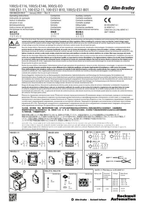
100-IN022D-EN-EJanuary 2022Rev. E1/4100(S)-E116, 100(S)-E146, 300(S)-EOOperating instructions Instruções de operação Notice d’utilisation Istruzioni d'uso BetriebsanleitungContactors Contatores Contacteurs Contattori Schütze Auxiliary contacts Contatos auxiliares Contacts auxiliaires Contatto ausiliari HilfsschalterInstrucciones de operación Contactores Contactos auxiliaresAttention! Attenzione! Achtung!¡Atención!Внимание!100-ES1-11, 100-ES2-11, 100-ES1-B10, 100(S)-ES1-B01Atenção!Инструкции по эксплуатацииКонтакторыВспомогательные контактыIEC/EN 60947-4-1UL 60947-4-1CAN/CSA-C22.2 No. 60947-4-1GB/T 14048.41523A1A2ON OFF_N COM 960V95+24 V Contactor StartSt opSupply voltageRelayX Note: Emergency stop should disconnect A1 and A2Code ED and EN built-in PLC interfaceOperation is controlled by separate logic control signals from, for instance, a PLC. Use of logic control requires a steady supply voltage on A1 and A2 within the rated voltage range, as described forcode KJ, KY, KD and KN (J, Y, D, B). The function of the logic control signal will no longer be guaranteed when the supply voltage on A1 and A2 is removed.The logic control signals are operated with 24V DC. There are two control signals (ON and OFF_N) and a common reference (COM). For the control signals, the function is guaranteed from 15V DC (6mA) to 33V DC (20mA).The contactor is closed by a control signal ON and opened by removal of control signal from OFF_N. The functions are described in diagram below. “1” means 24V DC between the control signal and COM. “0” means no voltage between the control signal and COM. Minimum control signal pulse length for opening and closing is 10ms. To connect the PLC interface, use cable dimension of max 1.5mm 2.General100(S)-E and 300(S)-EO contactors are if tted with an electronic interface. For a given coil, this allows the contactor to accept a very wide voltage range.Code KJ, KD, KN (J, Y, D, B)Operation is done, as with conventional contactors, by applying and removing supply voltage on A1 and A2. Closing 85% and opening at 55% of the lower nominal voltage limit, which is indicated in the functional diagram.When used with switches the wiring can be done according to diagram above4/4TYPE100(S)-E116FLAHerm. ref. comp,AC-8a 1168001602001601050LRA 100(S)-E146Ballast, A C-5a/Resistance air heatingElevator duty54541010010100Circuit Breaker A Fuse A/Class65100100100Max Short Circuit Current at 480V (kA)25356510018222550140G-J 140G-J2140G-J3140G-J6140G-J0510101001001006525200/J 200/J 140G-J6140G-J Type 2250/J250/RK5Max Short Circuit Current at 600V (kA)Circuit Breaker AFuse A/Class Max Short Circuit Current at 208-240V (kA)Max Short Circuit Current at 480V (kA)Type 1Max Short Circuit Current at 600V (kA)For applications above 690V, terminal shrouds 100-ETS146L should be used.UL/CSMax 600VAC, 50/60 Hz:2001601050300(S)-EO 54100(S)-E116, 100(S)-E146, 300(S)-EO100(S)-E116, 100(S)-E146, 300(S)-EOAccording to UL 60947-4-1 Use wire Cu 75 only. Use built-in cable clamps or UL recognized compression lugs. Enclosure with min. dimension 24 by 20 by 10 inches should be used. Suitable for use on a circuit capable of delivering not more than the max symmetrical amperes at the max voltage shown in the table below.Copyright © 2022 Rockwell Automation, Inc. All Rights Reserved. Printed in Sweden.Allen-Bradley, Rockwell Software, and Rockwell Automation are trademarks of Rockwell Automation, Inc.Trademarks not belonging to Rockwell Automation are property of their respective companies.Rockwell Automation maintains current product environmental information on its website at /rockwellautomation/about-us/sustainability-ethics/product-environmental-compliance.page.DIR 10002941731 (Version 04)Publication 100-IN022D-EN-E January, 2022。
欧洲贵族说明

安装和维护说明(专业人员使用)冷凝式燃气壁挂炉欧洲贵族6 720 613 303-00.1OZSB 28-3 | ZB 42-3 | ZWB 30-3 | ZWB 42-36 720 617 603 (2008/08 C N )2 | CN6 720 617 603 (2008/08)目录1标识说明和安全提示 . . . . . . . . . . . . . . . . . . . . . . . .41.1标识说明 . . . . . . . . . . . . . . . . . . . . . . . . .41.2安全提示. . . . . . . . . . . . . . . . . . . . . . . . . .42供货范围 . . . . . . . . . . . . . . . . . . . . . . . . . . . . . . . . .63设备说明. . . . . . . . . . . . . . . . . . . . . . . . . . . . . . . . .73.1适用条件 . . . . . . . . . . . . . . . . . . . . . . . . .73.2型号一览 . . . . . . . . . . . . . . . . . . . . . . . . .73.3铭牌 . . . . . . . . . . . . . . . . . . . . . . . . . . . .73.4一般说明 . . . . . . . . . . . . . . . . . . . . . . . . .83.5附件. . . . . . . . . . . . . . . . . . . . . . . . . . . . .83.6尺寸和最小间距 . . . . . . . . . . . . . . . . . . . .93.7ZSB 的内部结构. . . . . . . . . . . . . . . . . . .103.8ZWB 的内部结构. . . . . . . . . . . . . . . . . . .123.9ZB 的内部结构 . . . . . . . . . . . . . . . . . . . .143.10ZSB 的电路图. . . . . . . . . . . . . . . . . . . . .163.11ZWB 的电路图. . . . . . . . . . . . . . . . . . . .183.12ZB 的电路图 . . . . . . . . . . . . . . . . . . . . .203.13ZSB28-3的技术参数. . . . . . . . . . . . . . . .223.14ZWB30-3的技术参数. . . . . . . . . . . . . . .233.15ZWB42-3的技术参数. . . . . . . . . . . . . . .243.16ZB42-3的技术参数. . . . . . . . . . . . . . . . .253.17冷凝水成分. . . . . . . . . . . . . . . . . . . . . . .264法规 . . . . . . . . . . . . . . . . . . . . . . . . . . . . . . . . . . .275安装 . . . . . . . . . . . . . . . . . . . . . . . . . . . . . . . . . . .285.1重要说明 . . . . . . . . . . . . . . . . . . . . . . . .285.2检查膨胀罐的大小. . . . . . . . . . . . . . . . . .295.3ZB 型设备的膨胀罐和水泵的选择. . . . . . .295.4选择安装地点. . . . . . . . . . . . . . . . . . . . .305.5管道连接 . . . . . . . . . . . . . . . . . . . . . . . .305.6设备挂装. . . . . . . . . . . . . . . . . . . . . . . . .335.7检查接口 . . . . . . . . . . . . . . . . . . . . . . . .345.8特殊情况 . . . . . . . . . . . . . . . . . . . . . . . .346电气连接 . . . . . . . . . . . . . . . . . . . . . . . . . . . . . . . .356.1一般说明. . . . . . . . . . . . . . . . . . . . . . . .356.2设备电源线和插头的连接 . . . . . . . . . . . . .356.3附件的连接. . . . . . . . . . . . . . . . . . . . . . .356.3.1控制器和遥控器的连接 . . . . . . . . . . . . . .366.3.2水箱的连接. . . . . . . . . . . . . . . . . . . . . . .376.3.3地板采暖出水温度监控装置TB1的连接. . . . . . . . . . . . . . . . . . . . . . . . . . . . . . . 376.3.4ZB 型设备:3级供暖泵(附件编号1147)的连接. . . . . . . . . . . . . . . . . . . . . . . . . .376.4外部附件的连接 . . . . . . . . . . . . . . . . . . .386.4.1循环泵的连接. . . . . . . . . . . . . . . . . . . . .386.4.2外部出水温度传感器的连接(如:水力开关的温度传感器). . . . . . . . . . . . . .386.4.3在不带混水的负荷侧(二次回路)中连接外部供暖泵 . . . . . . . . . . . . . . . . . 386.4.4外部供暖泵(一次泵) (AC 230 V,最大100 W) 的连接. . . . . . . . . . . . . . . . 386.4.5ZB 型设备:水箱加热泵或三通切换阀(弹簧复位) (AC 230 V, 最大200W) . . . 396.5电源线的替换. . . . . . . . . . . . . . . . . . . . . 397运行调试. . . . . . . . . . . . . . . . . . . . . . . . . . . . . . . 407.1运行前准备. . . . . . . . . . . . . . . . . . . . . . 417.2打开/关闭设备. . . . . . . . . . . . . . . . . . . 417.3打开供暖功能 . . . . . . . . . . . . . . . . . . . . 427.4供暖控制调节 . . . . . . . . . . . . . . . . . . . . 427.5运行调试后. . . . . . . . . . . . . . . . . . . . . . 427.6ZWB 设备-生活热水温度调节 . . . . . . . . 437.7生活热水温度调节(带生活热水水箱). . . 437.8夏季模式. . . . . . . . . . . . . . . . . . . . . . . . 447.9防冻保护. . . . . . . . . . . . . . . . . . . . . . . . 447.10按键锁定. . . . . . . . . . . . . . . . . . . . . . . .448高温消毒. . . . . . . . . . . . . . . . . . . . . . . . . . . . . . . 459水泵防抱死功能. . . . . . . . . . . . . . . . . . . . . . . . . . 4610控制面板的操作. . . . . . . . . . . . . . . . . . . . . . . . . .4710.1一般说明 . . . . . . . . . . . . . . . . . . . . . . . . 4710.2服务功能一览 . . . . . . . . . . . . . . . . . . . . 4810.2.1一级服务功能 . . . . . . . . . . . . . . . . . . . . 4810.2.2二级服务功能 . . . . . . . . . . . . . . . . . . . . 5110.3服务功能说明 . . . . . . . . . . . . . . . . . . . . 5210.3.1服务等级1. . . . . . . . . . . . . . . . . . . . . . . 5210.3.2服务等级2. . . . . . . . . . . . . . . . . . . . . . .5711燃气类型 . . . . . . . . . . . . . . . . . . . . . . . . . . . . . . . 5811.1燃气/空气比例 (CO 2 或 O 2) . . . . . . . . . .5811.2检查燃气压力 . . . . . . . . . . . . . . . . . . . . 5912烟气测量. . . . . . . . . . . . . . . . . . . . . . . . . . . . . . . 6012.1烟道吹扫键. . . . . . . . . . . . . . . . . . . . . . 6012.2烟道密封性检查. . . . . . . . . . . . . . . . . . . 6012.3测量烟气中CO 的含量. . . . . . . . . . . . . .6013环境保护. . . . . . . . . . . . . . . . . . . . . . . . . . . . . . . 6114维护保养. . . . . . . . . . . . . . . . . . . . . . . . . . . . . . . 6214.1操作步骤. . . . . . . . . . . . . . . . . . . . . . . . 6314.1.1调取最后存储的故障信息(服务功能6.A). 6314.1.2冷水管上的过滤器(ZWB). . . . . . . . . . . . 6314.1.3板式换热器(ZWB) . . . . . . . . . . . . . . . . 6314.1.4检查电极. . . . . . . . . . . . . . . . . . . . . . . . 6414.1.5检查和清洁热交换器 . . . . . . . . . . . . . . . 65| 3CN 6 720 617 603 (2008/08)14.1.6检查燃烧器. . . . . . . . . . . . . . . . . . . . . . 6614.1.7清洁冷凝水虹吸管 . . . . . . . . . . . . . . . . . 6714.1.8检查混合装置的膜片 . . . . . . . . . . . . . . . 6714.1.9检查膨胀罐(参见29页). . . . . . . . . . . . 6714.1.10调节供暖系统的压力. . . . . . . . . . . . . . . . 6814.1.11检查电气连接 . . . . . . . . . . . . . . . . . . . . 6814.2维护保养清单(维护保养记录) . . . . . . . . 6915显示器显示 . . . . . . . . . . . . . . . . . . . . . . . . . . . . . 7016故障消除 . . . . . . . . . . . . . . . . . . . . . . . . . . . . . . . 7116.1在显示器中显示的故障. . . . . . . . . . . . . . 7116.2在显示器中不显示的故障 . . . . . . . . . . . . 7417供暖/热水功率设定值 . . . . . . . . . . . . . . . . . . . . . 7518运行调试记录. . . . . . . . . . . . . . . . . . . . . . . . . . . . 784 | CN6 720 617 603 (2008/08)1标识说明和安全提示1.1标识说明安全提示用来说明在不遵守相关说明的情况下出现危险的严重程度。
欧洲电器产品说明书

用一根两端带JR头的排线将电调与OTA Programmer连接起来,一端连接电调的独立编程口,一端连接OTA Programmer, 最后给电调上电。
再使用手机安装 HW LINK软件进行电调设置。
(详情请参阅LCD编程盒说明书)此电调支持使用LCD编程盒或利用LCD编程盒连接到电脑端来设置参数(使用HOBBYWING USB LINK软件),用一条两端带JR公头的排线将电调和编程盒连接,然后给电调接上电源,LCD 设定盒将显示出开机界面,按LCD 设定盒上任意按键,设定盒和电调开始建立通信,并显示“CONNECTING ESC” ,等待几秒后,将显示出当前的模式名 ,随后显示出第一个设置参数。
使用 “ITEM”和“VALUE” 按键即可更改设置参数,按“OK”键可将设置参数存入电调。
感谢您购买该产品!无刷动力系统功率强大,错误的使用可能造成人身伤害和设备损坏。
请在使用设备前仔细阅读说明书,严格遵守规定的操作程序。
我们不承担因使用本产品而引起的任何责任,包括但不参数说明2有以下几种恢复出厂参数方法:1) 利用Set键恢复出厂设置,方法如下:在油门摇杆处于中立点位置的任意时刻(除进行油门校调或编程设定时),按住 SET 键3秒以上,可恢复出厂设定。
红绿灯同时闪烁时表示恢复设定成功,出厂设定需重新上电方 可生效。
2) 利用LCD多功能编程盒恢复出厂设定:LCD编程盒与电调连通后,通过“ITEM”选项选到“RESTORE DEFAULT”项,然后再按下“OK”保存,即可恢复出厂设置。
3) 利用OTA模块(使用HW LINK 手机APP)恢复出厂设置OTA Programmer 与电调连通后,进入“参数设置“项目,点击”恢复出厂设置“按钮即可。
· 电调与相关连接部件连接前,请确保所有电线和连接部件绝缘良好,短路将会毁坏电调;· 请务必仔细连接好各部件,若连接不良,您可能不能正常控制赛车,或出现设备损坏等其他不可预知的情况;· 使用此电调前,请认真查看各动力设备以及车架说明书,确保动力搭配合理,避免因错误的动力搭配导致电机超载,最终损坏电调;· 若需对电调的输入输出线、插头做相关焊接时,为保证焊接牢靠,请使用至少50W功率的焊接设备进行焊接;· 勿使电调外部温度超过90℃/194℉,高温将会毁坏电调并且可能导致电机损坏;· 使用完毕后,切记断开电池与电调,因只要接着电池,即使开关未开电调也会一直消耗电流,长时间连接会导致电池最终完全放电;进而导致电池或电调或者二者故障; 我们不对因此而造成的任何损害负责。
Hoover 蒸汽熨斗使用说明书

Parts DescriptionIntroductionDear customer,First of all, we would like to congratulate you for purchasing this Hoover iron and tothank you for the confidence you have in Hoover brand.This appliance has been manufactured with great care, respecting all of our qualitycriteria and has been tested several times. We hope its use will fulfil your expectations.We are strongly convinced that it will make your ironing much faster and better.Before using your new Hoover appliance, please read carefully this user’s manual. Ifyou need further information or if you encounter any trouble which are not noticed inthis manual, please contact the after-sales service or your standard dealer.Important Safety InstructionsRead this user manual carefully before you first use and save it for future reference.This appliance can be used by childrenaged from 8 years and above andpersons with reduced physical, sensoryor mental capabilities or lack ofexperience and knowledge if they havebeen given supervision or instructionconcerning use of the appliance in asafe way and understand the hazardsinvolved. Children shall not play withthe appliance. Cleaning and usermaintenance shall not be made bychildren without supervision.2 - GB• This product has been designedfor domestic use only. In case of anycommercial use, inappropriate use orfailure to comply with the instructions, themanufacturer is not responsible and theguarantee will not apply.• Before connecting your appliance, checkif the mains voltage is the same as thevoltage indicated on your appliance andthat the power outlet is connected to theearth.• Ensure before each use that the electriccord or any other important part is notdamaged.• Keep the iron and its cord out of reachof children less than 8 years of age when itis energized or cooling down.• Never direct the steam towards persons oranimals. Never direct the steam jet towardsany other electrical or/and electronicappliances.• The iron is not to be used if it has beendropped, if there are visible signs ofdamage or if it is leaking.• If the appliance shows evidence ofbreakdown, malfunction, leakages. Pleasemake sure it is checked by an authorizedService Centre to avoid any danger.• Always make sure the appliance isswitched off, unplugged and cooled downbefore doing any maintenance work.3 - GB• The iron must not be left unattendedwhile it is connected to the supply mainsand before it has cooled down.• Do not unplug the appliance by pullingon the cord or on the appliance.• Never immerse the iron, the stand, thecable or the plugs in water. Never holdthem under the water tap.• The soleplate of the iron can becomeextremely hot and may cause burns iftouched. Never touch the electric cordswith the soleplate.• If the supply cord is damaged, it mustbe replaced by the manufacturer, serviceagent or similarly qualified persons inorder to avoid a hazard.• When placing the iron on its heel,ensure that the surface on which the heelis placed is stable.• The plug must be removed from thesocket-outlet before the water reservoir isfilled with water.• The surfaces with are liable to gethot during use.• To have a electronic copy of theinstruction manual contact the after salesservice in guarantee card.• The iron must be used and rested on astable surface.4 - GB5 - GB Chapter 1: Preparation for UseChapter 1.1 : What Kind of Water May be Used?Chapter 1.2 : Filling the Water TankPlace the iron on a stable and level surface, for example on the hard part of an ironing board or on a heat-resistant surface.The Hoover iron has been designed to be used with tap water only.There is no need to use distilled or pure distilled water.Nevertheless, in case you live in a hard water area, you can mix 50% of distilled water with 50% of tap water.Do not use any other kind of water or do not add any other contents to water tank as it can damage your appliance.Remove the mains plug from the wall socket before filling the iron.Set the steam button to position “0” or “ ” and open the water fill cover.Please fill your iron with normal tap water before using for the first time.Use the water beaker supplied to fill clean tap water into water tank until “MAX” filling level.Push the water fill cover firmly to close and dry any spilt water around the enclosure of the appliance, do not overfill.Warning: Do not add vinegar, hot water, perfume, or any other kind of chemical agents or any other contents in the water tank. It could damage the steam generator and shorten its life.Chapter 2: Using Your IronConnect the appliance with the mains cord to an earthed socket and switch the power on. Stand the iron in the vertical position, turn the temperature dial to your desired setting, the iron will make an alarm sound and the power light on the handle will start flashing in an Amber colour.Move your iron in one complete motion from the vertical position to horizontalreturning to the vertical position, on completion of this movement the light on the handle will illuminate Red and the soleplate will begin heating.When the red light switches off, your appliance is ready for use.n.B 1) The first time you use your appliance you may find some dust and smell of fumes , this is quite normal and they will quickly disappear. 2) Your Iron is fitted with a number of features for Safe use and these can be noted by the colour of light being illuminated on the handle: a) Amber light , this illuminates when the Iron is initially switched on and requires to be moved as described above . b) Red light , this illuminates when the Iron is in the heating mode and will turn off after it has reached the set temperature. c) Green light , this illuminate when the iron has been in the Stationary position for more than 30 secs and the power to the heating element has been cut off until theiron movement is started again.126 - GB Chapter 2.2 - IroningDry ironingFor dry ironing, turn the steam control knob to “0”or “ ” . This will cut off the steam flow if water is in the water tank.Turn the temperature control knob to select the desired fabric/temperature setting. The indicator power light will illuminate, ensure the iron is on a smooth and stable surface vertically.After the indicator power light goes out, you can begin to iron.Steam ironingAs indicated on the temperature control and the table on the rear of the iron, steam-ironing is only possible at higher ironing temperatures (between “●●” to “MAX”).Ensure that there is enough water in the water tank.Stand the iron on its end; Insert the mains plug into the wall socket.Set the temperature control knob at the required position within the steam area.After the indicator power light has gone out and has come on again, you may start ironing.aTTEnTiOn: Never direct the steam towards people. Burns or serious injury may occur.Cooling Feature *Turn on the fan by pushing FAN SWITCH to cool the handle and user environment.Push again to turn it off.Select the temperature of the soleplate by turning the dial on the iron to the desired position.Wait a few moments until the temperature indicator is off.It will indicate to you that the soleplate has reached the requested temperature.While ironing, the temperature dial indicator may turn on and off, the temperature adjusts without interrupting your ironing.HelpTo know the best suitable temperature for each textile, check the laundry care label of the article to be ironed. Please note that during use, the temperature light goes on from time to time. It signifies that the iron is heating up to the set temperature.If a fabric is made with various kinds of fibres always select the soleplate temperature to suit the most delicate one .If you select a lower temperature while ironing, wait until the iron has cooled down to the set temperature before you continue ironing.If the temperature is too low, some drops of water could escape from the soleplate. Please raise up the temperature above the 2 dots (••) to avoid this issue.Chapter 2.1: Regulating the Soleplate Temperature * Certain Models Only7 - GBChapter 2.4 - Shot of SteamEnsure that there is enough water in the water tank.When the temperature control knob is set to steam setting (between “●●” to “MAX”) strong steam can be used.Press the steam boost button, the soleplate will emit a strong flow of steam.nOTEOnly use the steam boost button when the steam iron has reached the steam or maximum temperature.Do not press the steam boost button more than 3 times repeatedly. For optimum steam output , leave an interval of at least 5 seconds between pressing the steam boost button.The steam boost button feature can be used with Dry or Steam ironing as desired.aTTEnTiOn: Never direct the steam towards people. Burns or serious injury may occur.HelpWhen steam ironing clothes on which shiny patches may occur, we recommend you to set the soleplate temperature to a lower temperature or to iron the garment on the reverse.Start with the fabrics that need to be ironed at a lower temperature (•) and finish with those that needed to be ironed at the higher temperature (•••/Max). Textile Soleplate T°CJeans MaxCotton •••Linen MaxStarched Clothes •••Velvet/Alcantara ••Wool ••Silk ••Cashmere ••Rayon ••Polyester •Nylon •Acrylic •Lycra •Polyamid •To obtain the best results, it is important to set the correct temperature of the soleplate.Chapter 2.3 - How to Choose the Correct Soleplate Temperature8 - GB Chapter 2.5 - SprayingChapter 2.6 - Vertical Shot Of SteamEnsure there is enough water in the water tank.Press the spray boost button to produce a fine spray of water from the nozzle and continue ironing.nOTE: Do not spray silk.When the temperature control knob is set to a steam setting (between “●●” to “MAX”) vertical steam can be used.Simply hold the iron vertically, positioned in front with a slight distance from the item to be steamed, and press the steam boost button.aTTEnTiOn: Never direct the steam towards people. Burns or serious injury may occur.nOTE: This is especially useful for getting wrinkles out of hanging clothes, curtains, wall hangings etc.Chapter 2.8 - Automatic Anti-Drip FunctionYour iron has an anti-drip function. The iron automatically stops generating steam when the temperature is too low to prevent water from dripping out of the soleplate.nOTE: When using the Steam function, your appliance may stop generating steam for several seconds, this is normal.Chapter 2.7 - Automatic Anti-Calc FunctionYour iron contains an anti-calc cartridge to reduce scale deposits. This considerably prolongs the operational life of your iron.The anti-calc cartridge is an integral part of the water tank and does not need to be replaced.Chapter 2.9 - Self-Clean FunctionUse the self clean function once every two weeks. If the water in your area is very hard, the self clean function should be used more frequently.Make sure the iron is unplugged.Set the steam control knob to OFF position.Fill the water tank to the maximum level.Put the plug in the wall socket.Select the maximum ironing temperature.Unplug the iron when the temperature power light has gone out.Hold the iron over the sink, press and hold the self clean button and gently shake the iron to and fro.Release the self clean button after 5-10seconds.Repeat the self clean process if the iron still contains a lot of impurities.nOTESteam and boiling water will come out of the soleplate, impurities and flakes(if any)willbe flushed out.aTTEnTiOn: Keep hands and body away from hot water.Do not push and hold the self clean button while ironing.9 - GB Chapter 3: Maintenance and CleaningChapter 2-10 Auto Shut off f unctionChapter 4: StorageTo prevent any risk of burns, all maintenance and cleaning operations should only be carried out when the unplugged appliance has cooled down for at least 2 hours.Before cleaning, set the steam control knob to the “0” or “ ”, unplug the iron from wall socket, and allow the appliance to completely cool down, and then clean with a damp cloth, do not immerse the unit into water or other liquids.Clean and empty the water tank after every use.If ironing clothes with high temperature, which is not recommended on the garment table, this will cause burns to your clothes and residue left on the soleplate of the unit, it is recommended that you iron over an old cloth to remove any residue from the soleplate.After use, set the steam control knob to the “0” or “ ”, disconnect the unit from mains socket, empty remaining water from water tank and then store the iron after it has been completely cooled down.Never use scouring pads, abrasive or chemical cleaners, or solventsEmpty the water tank.Coil the power cord on the back plate.Put the iron in the upright position on it’s heel.Wait at least 30 minutes allowing the sole plate to cool down.Then you can take away your appliance in order to store it safely and easily.Important InformationHoover spares and Consumables Always replace parts with genuine Hoover spares. These are available from your local Hoover dealer or direct from Hoover. When ordering spare parts, always check your model number.Hoover ServiceShould you require service at any time, please contact your local Hoover Service Office. Please see all the contact details below.a. The auto-shut-off function automatically switches off the iron if it has not been moved after 30 secs in horizontal position or after 8 mins in vertical position.b. The power light starts flashing to indicate that the iron has been switched off by the auto-shut-off function.c. To let the iron heat up again:1. Move your iron in one complete motion from the vertical position to horizontal returning to the vertical position2. if the temperature of the soleplate has dropp ed below the setting ironing temperature, the power light will turn on, please waiting until it goes out before you start ironing.3. If the power light does not turn on after you move the iron, the soleplate still has the right temperature and the iron is ready to use.SafetyHoo v er believes that independent approval is the best way of demonstrating safetyin design and manufacture.All Hoover irons have been manufactured in compliance of all safety regulationsand approved by the most qualified independent approval certification bodies.iSO 9001Hoover’s factories have been independently assessed for quality. Our products aremade using a quality system which meets the requirements of ISO 9001The EnvironmentThe symbol on this appliance indicates that this appliance may not betreated as household waste. Instead it must be handed over to theapplicable collection point for the recycling of electrical and electronicequipment. Disposal must be carried out in accordance with localenvironmental regulations for waste disposal. For more detailedinformation about treatment, recovery and recycling of this appliance,please contact your local city office, your household and waste disposal service orthe shop where you purchased the appliance.This product complies with the European Directives 2006/95/EC,2004/108/EC and 2011/65/EC.HOOVER Limited, Pentrebach, Merthyr Tydfil, Mid Glamorgan, CF48 4TU, UKYour guaranteeThe guarantee conditions for this appliance are as defined by our representative inthe country in which it is sold. Details regarding these conditions can be obtainedfrom the dealer from whom the appliance was purchased. The bill of sale or receiptmust be produced when making any claim under the terms of this guarantee.Subject to change without notice.10 - GB®Printed in P.R.C. PART No. 48014702/02。
- 1、下载文档前请自行甄别文档内容的完整性,平台不提供额外的编辑、内容补充、找答案等附加服务。
- 2、"仅部分预览"的文档,不可在线预览部分如存在完整性等问题,可反馈申请退款(可完整预览的文档不适用该条件!)。
- 3、如文档侵犯您的权益,请联系客服反馈,我们会尽快为您处理(人工客服工作时间:9:00-18:30)。
6 720 613 303-00.1O
冷凝式燃气采暖热水炉 ��������� ��������� ���������
冷凝式燃气壁挂炉 ���� ���� ����
ZSB ZSB 28-3 ZSB 28-3 ︱ 28-3 ︱ ZB ZB ︱ 42-3 42-3 ZB 42-3 ︱ ︱ZWB ZWB ︱ ZWB 30-3 30-3 30-3 ︱ ZWB ︱ ZWB 42-3 42-3 42-3 S5523) | L1G40-(ZWB42-3A23 S5523) N1G27-(ZSB28-3A23 S5523) | N1G40-(ZB42-3A23 S5523) | L1G30-(ZWB30-3A23 ZSB 28-3 ︱ ZB 42-3 ︱ ZWB 30-3 ︱ ZWB ZWB 42-3
6 720 (2008/08) 6 720 648617 852604 (2011/05 CN)
|7
2
����
图1
6 720 617 648 604 852 (2008/08) (2011/05 CN)
6 720 613 303-10.1O
8|
10 | Übersicht der Bedienelemente
冷凝式燃气壁挂炉 ZSB 28-3 | ZB 42-3 | ZWB 30-3 ZSB 28-3 | ZB 42-3 | ZWB 30-3 | ZWB 42-3
安装和维护说明 ( 专业人员使用 )
6 720 613 303-00.1O
2|
6 720 (2008/08) 6 720 648617 852604 (2011/05 CN)
|5
检�和保� �温�� 建议客户:与具有许可得专业公司签订维修及维护合同,进行年检, B B ����! 并根据需要进行维护。 监控温度超过 60°C。 ( →第 27 页 )。 B 运营商对供暖设备的安全和环保负责 ( 《联邦清洁空气法》 ) 。 |5 检�和保� B 只可使用原装备件! B 建议客户:与具有许可得专业公司签订维修及维护合同,进行年检, 并根据需要进行维护。 ��性和��可燃材料 �温�� 运营商对供暖设备的安全和环保负责 ( 《联邦清洁空气法》 ) 。 不可在设备附近使用或存储可燃的材料 (纸张、稀释剂、油漆等) B B ����! 60°C。 ( →第 27 页 )。 B 监控温度超过 只可使用原装备件! 燃烧 / 室内空气 检�和保� ��性和�度可燃材料 B 燃烧和室内空气不可含有腐蚀性物质 (例如含有氯化物和氟化物的 卤代烃) ,以避免腐蚀设备。 B 建议客户:与具有许可得专业公司签订维修及维护合同,进行年检, 不可在设备附近使用或存储可燃的材料 (纸张、稀释剂、油漆等) 并根据需要进行维护。 误使用风险 燃烧 / 室内空气 安装不当会引起对人、畜和物的危害; B B 运营商对供暖设备的安全和环保负责 ( 《联邦清洁空气法》 ) 。 B 器具安装应严格按照说明书要求和相关规定执行; B 燃烧和室内空气不可含有腐蚀性物质 (例如含有氯化物和氟化物的 B B 只可使用原装备件! 只有制造商授权的代理商或技术人员才可以维修、更换零部件或整机; 卤代烃) ,以避免腐蚀设备。 B 应使用原装配件,以免降低产品的安全性; B 应使用原配烟道,不能随意改动其他烟道,严禁用单烟道代替同轴 ��性和�度可燃材料 烟道; B B 不可在设备附近使用或存储可燃的材料 (纸张、稀释剂、油漆等) 器具维修时涉及烟气调压阀和控制器的维修应找器具制造商; B 不应购买经销商改装的器具,以确保安全性; B / 安装器具时应在器具前的管道上安装燃气截止阀; 燃烧 室内空气 B 器具不应靠近电磁炉、微波炉等强电磁辐射电器安装; B B 燃烧和室内空气不可含有腐蚀性物质 (例如含有氯化物和氟化物的 严禁拆动器具上的任何密封件; 卤代烃) ,以避免腐蚀设备。 B 器具清洁时不应使用有腐蚀性的清洁剂; B 器具严禁安装在卧室、客厅、浴室; B 儿童以及不会使用的人不得操作器具,严禁儿童玩弄器具; B 用户自己不应动采暖安全阀和采暖水排泄阀,应由专业人员来处理; B 器具不宜暗装; B 维修和检查人员在产品维修后应在产品上进行标示维修和检查结果 B 房间的配电系统应有接地,器具连接的开关不应设备在有浴盆或淋 浴设备的房间;插头、插座应通过相关认证; B 指出器具防冻功能起作用的条件,提示用记为了避免器具或管路冻 坏,在冬季长期停机时,应将器具采暖和生活热水系统内的水全部 排空;或者只排生活热水,而在采暖水中加入防冻剂; B 锁定装置不应随意调节;
6 720 617 648 604 852 (2008/08) (2011/05 CN)
6|
1.2
标志说明
具有警告三角形标记和灰色背景的文字��说明。
提示用语用来说明在不遵守相关说明的情况下,所出现的危险的严重程 度。 • • ��表示可能出现轻度损失。 警告表示可能出现轻度人员伤害或严重的财物损失。 标记有此标志的文字提示。这些提示在上方和下方有直 线框。 提示包含不会对人或设备造成危险的情况下的重要信息。
6 720 617 648 604 852 (2008/08) (2011/05 CN)
4| 4|
1 安��明和���明 1 安��明和���明 1 安��明和���明 1.1 安��明 1.1 安��明 4|
燃气气��� B B 关闭燃气阀门 关闭燃气阀门 ( (→ →第 第8 8页 页) )。 。 燃气气��� B 关闭燃气阀门 ( → 第 8 页 )。 打开窗户。 B 打开窗户。 B 关闭燃气阀门 ( → 第 8 页 )。 打开窗户。 B B 不要操作电气开关。 不要操作电气开关。 1.1 安��明 B 打开窗户。 不要操作电气开关。 B 熄灭明火。 熄灭明火。 B B 熄灭明火。 B 不要操作电气开关。 在��给燃气供应公司和具有许可的专业公司打电话。 燃气气��� B 在��给燃气供应公司和具有许可的专业公司打电话。 B 关闭燃气阀门 熄灭明火。 在��给燃气供应公司和具有许可的专业公司打电话。 B ( → 第 8 页 )。 �气气��� �气气��� B 打开窗户。 在��给燃气供应公司和具有许可的专业公司打电话。 B �气气��� B 关闭设备 B 关闭设备 ( (→ →第 第 15 15 页 页) )。 。 B 不要操作电气开关。 �气气��� B 关闭设备 ( → 第 15 页 )。 打开门窗。 B 打开门窗。 B 熄灭明火。 B 关闭设备 ( → 第 15 页 )。 打开门窗。 B 通知具有许可的专业公司。 B B 通知具有许可的专业公司。 在��给燃气供应公司和具有许可的专业公司打电话。 B 打开门窗。 通知具有许可的专业公司。 安装和改装 安装和改装 B 通知具有许可的专业公司。 �气气��� 安装和改装 B 只能由具有许可的专业公司安装或改装设备。 B 只能由具有许可的专业公司安装或改装设备。 B 关闭设备 ( → 第 15 页 )。 安装和改装 只能由具有许可的专业公司安装或改装设备。 B 不可随意改装烟道的任何部件。 B 不可随意改装烟道的任何部件。 B 打开门窗。 B 只能由具有许可的专业公司安装或改装设备。 不可随意改装烟道的任何部件。 B 在��空气����下:不可封闭或缩小门、窗和墙壁上的通风口 B B 在��空气����下:不可封闭或缩小门、窗和墙壁上的通风口 通知具有许可的专业公司。 B 不可随意改装烟道的任何部件。 和排气口。在安装接缝密封窗户的情况下,要确保燃烧所需空气的 在��空气����下:不可封闭或缩小门、窗和墙壁上的通风口 和排气口。在安装接缝密封窗户的情况下,要确保燃烧所需空气的 供应。 和排气口。在安装接缝密封窗户的情况下,要确保燃烧所需空气的 B 在��空气����下:不可封闭或缩小门、窗和墙壁上的通风口 供应。 安装和改装 供应。 B 锁定装置不应随意调节。 和排气口。在安装接缝密封窗户的情况下,要确保燃烧所需空气的 B 只能由具有许可的专业公司安装或改装设备。 供应。 燃气转换 B 不可随意改装烟道的任何部件。 B 在��空气����下:不可封闭或缩小门、窗和墙壁上的通风口 燃气转换说明详见安装和维护说明书,燃气转换和调节只能由制 B 造商认可的专业人员进行,调节结束后应将调解器锁定,并加贴 和排气口。在安装接缝密封窗户的情况下,要确保燃烧所需空气的 标识。 供应。 用户应遵守警告事项
6 720 6 720 617 617 604 604 (2008/08 (2008/08 CN) CN) 648 604 852 (2008/08 (2011/05 CN) 6 720 617
6 720 617 604 (2008/08 CN)
操作说明 操作说明 操作说明 操作说明
���� ����
| 11
���� B 用扳手转动四角头,直到凹槽指向水流方向。 凹槽与水流方向横向交叉 = 关闭。
1.
6 720 615 066-04.1O
图4
6 720 617 648 604 852 (2008/08) (2011/05 CN)
4|
1.1 安��明 燃气气��� 燃气气��� 1.1 安��明
1
安��明和���明
高温消毒
B 烫伤危险! 监控温度超过60℃。(→第27页)。
6 6 720 720 617 617 604 604 (2008/08) (2008/08) 6 720 617 604 (2008/08) 6 720 (2008/08) 6 720 648617 852604 (2011/05 CN)
供专业人员使用的烟道吹扫键 (参见安装说明) 供专业人员使用的维修键 (参见安装说明) 燃烧运行状态指示灯 燃烧器运行信号灯 总开关 按键锁定 eco 键 复位键 显示器 热水温度调节旋钮 压力表 此处可安装一个室外温度补偿控制或一个定时器 (附件) 出水温度调节旋钮 燃烧运行指示灯(持续亮)/故障(闪亮) 运行指示灯 供暖出水阀 热水阀 燃气阀 (关闭) 冷水阀 供暖回水阀 漏斗虹吸管 (附件)