Flotherm教程4FurtherRefinementSolidTemperatures
Flotherm瞬态分析
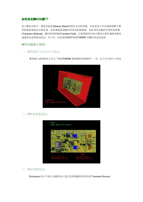
如何设定瞬时问题??电子散热分析中,通常以稳态(Steady State)结果作为分析依据,在此状况下可以观察到整个模型热场流场稳定后的结果。
如需观察温度随时间变化的曲线图,则必须设定随时间变化的热源(Transient Attribute)、瞬时时间网格(Transient Grid),以便观察各时间点整体计算区域的热量传递速度及流体扰动状态。
以下以一实际案例解释FLOTHERM中瞬时设定的流程。
瞬时问题建立流程:一、模型建立与几何尺寸设定:模型建立请参照本公司之”FLOTHERM基础课程训练教材”一书。
以下为几何尺寸设定二、PCB板热源设定:三、瞬时热源设定:Enclosure的六个面上均提供如上图之发热量随时间变化的Transient Source。
四、数值结果显示及说明:由上图结果可以得知,在350秒的时候NC1芯片已超过最大容许温度摄氏125度,所以在350秒的时候此装置已无法正常运作。
五、图形化后处理:问答集Question 1:使用FLOTHERM解决瞬时问题需注意的事项。
Answer:(1) 必须设定材质的密度(Density)及比热(Specific Heat)。
一般求解稳态的案例中,因密度及比热不随时间的变化,所以可以忽略不设定。
(2) 时间网格( Transient Grid )。
FLOTHERM为一自动网格系动热流仿真软件,当设定瞬时热源以后,软件本身会自动设定其时间网格。
所以当求解瞬时问题时,可先设定瞬时热源再设定时间网格。
Question 2:如何设定瞬时热源?!Answer:瞬时热源顾名思义为发热量随时间而改变,FLOTHERM中提供以下几种热源设定。
Question 3:瞬时收敛性的问题。
Answer:瞬时问题收敛性有关于模型本身物理性的网格与时间性网格的设定。
当无法收敛的时候两者都必须作网格收敛性的测试。
详情请参阅Flomerics 网站( /)中的技术文件”Convergence and Transient Simulation”何谓局部加密?? <TOP>局部网格加密理论Validation - 1D ConductionWithout validation of the most basic of cases there is no way trust can be gained in the localized grid solution of more complex models. This model shows that a perfect linear variation in T in this conduction only analysis is predicted both with and without the use of localized grid. It is my belief that if this case was set up and solved in competitive codes that offered such a gridding capability there would be ‘kinks’ in the T profile, kinks that are highly sensitive to the quality of the grid.Validation - 2D Conduction,Getting slightly more complex...Validation - 2D Convection,The first graph indicates that there is a difference. The second graph is for a much finer grid both localized and non-localized. This therefore demonstrates that the difference observed in the first graph was because BOTH localized and non-localized were not grid independent." Don't assume that if localized does not equal non-localized that the localized grid is wrong some how"。
FloTHERM基础培训教程PPT课件

1 2
A1 V1 = A2 V2
V1 A1
1 2
p2 V2
V2 A2
12
FLOTHERM 软件介绍
全球第一个专门针对电子散热领域的CFD软件
— 通过求解电子设备内外的传导\对流\辐射,从而解决热设 计问题
据第三方统计,在电子散热仿真领域,FloTHERM 全球市场占有率达到70%
据我们的调查,98%的客户乐意向同行推荐 FloTHERM
保证模型准确度1515flothermpreprocessingmodelingmeshingboundaryconditionsinitialconditionssourcesmaterialpropertiesphysicalmodelssolvermonitoring1616flothermpostprocessingtemperatureprofilespeedvectorcommandcenter优化differentcasessolveprogress1717simplecase求解监控与后处理1818flothermprojectmanager项目管理器提供树状结构的几何体和模型数据管理drawingboard模型绘图板提供创立和修改几何模型的简易界面面向对象的建模技术专业针对电子热分析的参数化模型完全三维cad风格1919flothermtable数据表窗口提供输入输出参数的数据表输出visualeditor图形输出窗口提供结果的图形动态输出2020flotherm库文件区项目文件索引文件2121flotherm首先flotherm软件借助四个目录管理文件管理每个项目文件千万别去尝试去修改项目文件中名中的数字串项目文件夹2222定义求解域2323设置
核心热分析模块
FloTHERM.Pack
flotherm散热学习(中文教程)(2021年整理精品文档)

flotherm散热学习(中文教程)flotherm散热学习(中文教程)编辑整理:尊敬的读者朋友们:这里是精品文档编辑中心,本文档内容是由我和我的同事精心编辑整理后发布的,发布之前我们对文中内容进行仔细校对,但是难免会有疏漏的地方,但是任然希望(flotherm散热学习(中文教程))的内容能够给您的工作和学习带来便利。
同时也真诚的希望收到您的建议和反馈,这将是我们进步的源泉,前进的动力。
本文可编辑可修改,如果觉得对您有帮助请收藏以便随时查阅,最后祝您生活愉快业绩进步,以下为flotherm散热学习(中文教程)的全部内容。
FLOTHERM/China/1/06 V6 Issue 1.0练习题 1: FLOTHERM软件的基本操作本练习通过创建一个非常简单的算例让用户对Flotherm软件的操作有一个基本的了解。
本练习逐步指导用户完成安放在钢板的热模块的创建,具体步骤如下1.创建和保存一个新的项目2.创建实体3.定义网格、求解4.分析结果FLOTHERM/China/1/06 V6 Issue 1.0 Page 2练习题 1: FLOTHERM软件的基本操作从[开始/程序/ Flomerics/FLOTHERM 6。
1/FLOTHERM 6。
1]启动FLOTHERM或用桌面快捷键出现彩斑屏幕,接着项目管理窗口(ProjectManager以下简称PM)会自动打开.FLOTHERM/China/1/06 V6 Issue 1.0 Page 3单击项目管理窗口(PM)的顶部菜单条’Project’(项目),下拉菜单,选择‘Save As’(另存为).在顶部的数据框(文本‘Project Name'(项目名称)右边)中键入项目名称“Tutorial 1”,另外在‘Title’(标题)输入框中键入“FirstFlotherm Tutorial"点击按钮‘Notes’(备注),打开输入框让用户输入项目相关注释,如:在下面我们可以用改变的日志区分建模过程,现在,只要点击按钮‘Date’(日期) 把当前的日期加入文本区。
flotherm教学资料
6
學習項目 1
學習項目 熟悉各種工作視窗
7
熟悉各種工作視窗
No 1 2 3 4 5 6 7
工作視窗 Project Manager Drawing Board Flow Motion Tables Profiles FLO/MCAD Visualization
8
熟悉各種工作視窗
No 1 2 3 4 5 6 7
切換 指標/游擊手 叫出/關閉 繪圖列 隱藏物體 回覆至原來的畫面
16
細部操作 於上課中詳述
學習項目 3
學習項目 熟練各種模型的建法
17
熟練各種模型的建法
No 工作視窗 1 2 3 4 5 6 7
功能
產生一個 矩型體
用途
最常用 機殼上的通風口 CPU 的熱源
Cuboid
Resistance 產生一個 流阻 Source PCB Enclosure Fan Region
細部操作 於上課中詳述
25
學習項目 4
學習項目 利用MCD將Pro/E的圖型轉入Flotherm
首先, 將 Pro/E 的圖轉成 IGS 檔.
26
啟動 FLOMCAD 視窗
27
呼叫 IGES 檔案 1
28
呼叫 IGES 檔案 2
選擇要轉入的 IGS 檔.
29
呼叫 IGES 檔案 3
轉入成功!
指標: 選取
14
學習項目 2
學習項目 熟練快速鍵
15
快速鍵
No 快速鍵 功能 1 2 3 4 No 快速鍵 功能
F3 F4 F5 F6
目錄管理:獨立出來 目錄管理:完全關閉 目錄管理:回到上一層 目錄管理: 完全展開
FLOTHERM经典教材
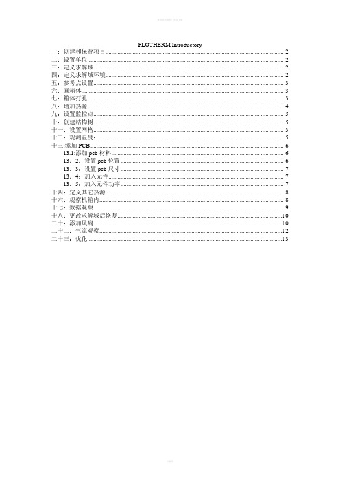
FLOTHERM Introductory一:创建和保存项目 (2)二:设置单位 (2)三:定义求解域 (2)四:定义求解域环境 (2)五:参考点设置 (3)六:画箱体 (3)七:箱体打孔 (3)八:增加热源 (4)九:设置监控点 (5)十:创建结构树 (5)十一:设置网格 (5)十二:观测温度: (5)十三:添加PCB (6)13.1:添加pcb材料 (6)13.2:设置pcb位置 (6)13.3:设置pcb尺寸 (7)13.4:加入元件 (7)13.5:加入元件功率 (7)十四:定义其它热源 (8)十六:观察机箱内 (8)十七:数据观察 (9)十八:更改求解域后恢复 (10)二十:添加风扇 (10)二十二:气流观察 (12)二十三:优化 (13)一:创建和保存项目在PM中选择[Project/New]并选择“Defaults” 表. 选中文件“DefaultSI” 并按OK. 这就按缺省设置(标准国际单位)打开一个新的工程文件,其它的设置参数也都回复为缺省值。
在PM中选择[Project/Save As](项目/保存为)。
—在Project Name (项目名称)栏中键入“Tutorial 2”。
—在Title(标题)栏中键入“Simple Electronics Box”。
—单击Notes(备注)按钮。
在文本编辑框中输入一些和项目有关的信息。
比如“This is an initial model of the electronics box.”。
单击Date(日期)和Time(时间)按钮,为项目创建日期和时间信息。
单击OK按钮,退出Edit Notes(备注编辑)对话框。
再单击确定(OK)来保存您的项目。
二:设置单位整体的缺省尺寸单位可在PM中设置。
在菜单条上, 选择[Option/Units].在‘Unit Class,’ 下面选中‘LENGTH’ 并在‘Use Units’ 中选择‘mm’。
FloTHERM基础培训教程PPT课件
31
材料定义
32
材料定义
1)直接定义;
2)使用库;
33
功耗定义
Thermal Attribution
Thermal Attribution
✓固定温度
✓固定热流量 ✓固定总功耗 ✓焦耳发热 ✓体积\面积热流 ✓热功耗随温升变化 ✓热功耗随时间变化
34
设定监控点
Step1:选定要监控的元件
监控点生成,默认位置为选 定元件的几何中心
热仿真基本理论
---控制方程
能量守恒方程
Hot component
T u T v T w T T T T
t x y z x c p x y c p y z c p z S T Tm11
Q
T2 m2
动量守恒方程
保证模型准确度flotherm1515preprocessingmodelingmeshingboundaryconditionsinitialconditionssourcesmaterialpropertiesphysicalmodelssolvermonitoringflotherm1616postprocessingtemperatureprofilespeedvectorcommandcenter优化differentcasessolveprogresssimplecase求解监控与后处理1717flotherm1818projectmanager项目管理器提供树状结构的几何体和模型数据管理drawingboard模型绘图板提供创立和修改几何模型的简易界面面向对象的建模技术专业针对电子热分析的参数化模型完全三维cad风格flotherm1919table数据表窗口提供输入输出参数的数据表输出visualeditor图形输出窗口提供结果的图形动态输出flotherm2020库文件区项目文件索引文件flotherm2121首先flotherm软件借助四个目录管理文件管理每个项目文件千万别去尝试去修改项目文件中名中的数字串项目文件夹定义求解域2222设置
Flotherm学习教程

Flotherm 介紹 2
CFD 软件在计算什么呢? 所有CFD软件均是在计算 压力, 速度, 温度, 此三个变数. 因
为此三个变数是构成流体力学, 热传学的基本物理量. 由于速度是向量, 所以在表达速度时, 习惯以X, Y, Z 三个方
向的分量来做表示. 亦即 Vx, Vy, Vz. 因此, CFD 软件在求解 五个变数,
2 Library.便会自动出现右边画面
3
在 Selection Form 下 选择 Project. 此时将 会出现 HS1
在中间栏位 输入 Heat Sink, 按 Save. (此 4 动作是在 Library 里建立一个Heat Sink 的
群组, 并将HS1存此此群组下.)
结束. 退出视窗. 可到Project 5 Manager/External/Library 里去检查是否有
学习项目 2
学习项目 熟练快速键
快捷键
No 快速键 功能
1 F3 目录管理:独立出来 2 F4 目录管理:完全关闭 3 F5 目录管理:回到上一层 4 F6 目录管理: 完全展开 5 F9 切换 指标/游击手 6 F7 叫出/关闭 绘图列 7 F12 隐藏物体 8 R 回覆至原来的画面
No
快速 键
以 单一 Smart Part 为例
步骤
1 先随便建一个 heat sink.
2
点选之, 按右键, 进入 Location. 便会 自动出现右边画面
选择 HS1. 按下 Load. (此动作是将 Library 里Heat Sink 群组下的HS1 3 呼叫进目前的专案.)
4 结束. 退出视窗
(2)将Library里的物体 呼叫进 现在的专案里(续)
FloTHERM基础培训教程PPT课件
t u x u u y u v z u w p x x u x y u y z u z S u Vp11
质量守恒方程
uvw 0
t x y z
1 2
A1 V1 = A2 V2
V1 A1
1 2
p2 V2
V2 A2
12
FLOTHERM 软件介绍
全球第一个专门针对电子散热领域的CFD软件
— 通过求解电子设备内外的传导\对流\辐射,从而解决热设 计问题
据第三方统计,在电子散热仿真领域,FloTHERM 全球市场占有率达到70%
据我们的调查,98%的客户乐意向同行推荐 FloTHERM
热仿真基本理论
---控制方程
能量守恒方程
Hot component
T u T v T w T T T T
t x y z x c p x y c p y z c p z S T Tm11
Q
T2 m2
动量守恒方程
热仿真软件-FloEFD 高级热测试仪
3
Contents
L1 – Introduction of Electronics cooling L2 – Basic theory of CFD L3 – Introduction of FLOTHERM L4 – Basic theory of using FLOTHERM to do simulation L5 – Build, solve and analyze a simple case L6 – Model popular electronics component L7 – Do a good grid L8 – Diagnose solution Problems L9 – Import your CAD model to do CFD simulation
- 1、下载文档前请自行甄别文档内容的完整性,平台不提供额外的编辑、内容补充、找答案等附加服务。
- 2、"仅部分预览"的文档,不可在线预览部分如存在完整性等问题,可反馈申请退款(可完整预览的文档不适用该条件!)。
- 3、如文档侵犯您的权益,请联系客服反馈,我们会尽快为您处理(人工客服工作时间:9:00-18:30)。
ρ Board Volume . conductor
10
Flotherm 4.1 Lecture 4 << Index >>
Options for conductivity model
Layer Definition
– Set number of layers – Set thickness and
All require dielectric and conductor materials
All result in a single PCB with an othotropic conductivity
7
Flotherm 4.1 Lecture 4 << Index >>
Options for conductivity model
T0220 Component
Compact to Detailed
13
Flotherm 4.1 Lecture 4 << Index >>
Components
Increased detail means: Increased accuracy Increased realism But also: Solutions take longer Design changes take
Modeling PCBs II
Changing the Modeling level to Conducting
The size section now requires a thickness in the Z direction.
The Dielectric and Conductor Materials must be specified.
coverage for each layer
11
Flotherm 4.1 Lecture 4 << Index >>
Modeling PCBs II
The PCB SmartPart can always be overwritten with other cuboids lower in the project manager list to represent ground-planes, thermal vias etc.
Alternatively the PCB structure could be constructed in greater detail using individual cuboids to represent the layered structure.
Area of increased conductivity to account for thermal vias
6
Flotherm 4.1 Lecture 4 << Index >>
Modeling PCBs II
There are three choices for conductivity model
– Percentage Conductor by Volume – Board Mass – Layer definition
5
Normal Conductivity (W/mK)
Flotherm 4.1 Lecture 4 << Index >>
Modeling PCBs I
The PCB Smart Part will internally create a cuboid with Orthotropic Material Properties The Summary section details the computed values of In Plane and Normal Conductivity together with other useful information relating to the PCB SmartPart
Percentage conductor by volume
9
Flotherm 4.1 Lecture 4 << Index >>
Options for conductivity model
Board Mass
– Minimum value
ρ Board Volume . dielectric
<< Index >>
Lecture 4A
Further Refinement: Solid Temperatures
Review
Flotherm 4.1 Lecture 4 << Index >>
Started simply
– Base modeling Level
– Enclosure Walls Thin – PCB Conducting – Components as heat sources over whole PCB
Give more detailed results
– Accurate air flow and temperatures local to the components
– Solid temperature for components
4
Flotherm 4.1 Lecture 4 << Index >>
Only gives general results
– Air flow patterns – Air temperatures
2
Flotherm 4.1 Lecture 4 << Index >>
Refine the Model
Add detail to the PCB
– Options for conductivity model – Discrete components
Layered cuboids of FR4 Copper
Detailed PCB Structure
12
Flotherm 4.1 Lecture 4 << Index >>
Components
Components can be represented by: PCB Component Compact Component Cuboids & Thermals Sources